NX-2420 MULTI-FONT NX-2420 RAINBOWICOLOUR USERS MANUAL NOT INTENDED FOR SALE
Federal Communications Commission Radio Frequency Interference Statement This equipment has been tested and found to comply with the limits for a Class B digital device, pursuant to Part 15 of FCC Rules. These limits are designed to provide reasonable protection against harmful interference in a residential installation.
HOW TO USE THIS MANUAL This manual is organized into nine chapters. To learn how to make the best use of your printer you are urged to read through chapters 1 through 3. The remaining chapters may be treated as a reference guide for programming operations, etc. It assumes a degree of knowledge of the operation of computers (for instance, it assumes you know about hexadecimal numbers).
Chapter 6 - MS-DOS and your printer Since the PC or PC-AT family of computers running under MS-DOS is currently the most popular configuration of microcomputer, we have included a few hints and tips to help you use your printer with such systems. Since virtually all PCs are sold with a Microsoft BASIC interpreter, we have also included some hints, and a sample program in this language to demonstrate the capabilities of the printer.
FEATURES OF THE PRINTER This printer has a full complement of features, making it an excellent partner for a personal computer. It supports the IBM/Epson printer commands and character sets, enabling it to print just about anything your computer can generate, both text and graphics. Some of its main features are the following: l Versatile paper handling Single sheets, fanfold forms, and multi-part forms (up to 5ply) are all accepted, and you can use either push/pull tractor or friction feed.
TABLE OF CONTENTS Chapter 1 SETTING UP THE PRINTER Locating the Printer Unpacking and Inspection Checking the carton contents Identifying printer parts Setting Up Mounting the platen knob Installing the ribbon cartridge and the roller unit Installing the optional cartridge Connecting the printer to your computer Loading Single Sheets Automatic loading Manual loading Loading and Parking Fanfold Forms Loading the paper from the rear of the printer Loading the paper from the bottom of the printer Paper parking
Forward micro-feed Reverse micro-feed Changing the auto loading value Clearing the buffer/All reset Selecting the print color Store macro definition Chapter 3 DEFAULT SETTINGS How to set the EDS mode Functions of the EDS settings Bidirectional test/Adjustment mode Chapter 4 PRINTER CONTROL COMMANDS Font Control Commands Character Set Commands Character Size and Pitch Commands Vertical Position Commands Horizontal Position Commands Graphics Commands Download Character Commands Color Selection Commandes Oth
Chapter 7 TROUBLESHOOTING AND MAINTENANCE Troubleshooting Power supply Printing Paper feeding Maintenance Replacing the Print Head 111 111 112 112 114 117 117 Chapter 8 SPECIFICATIONS 119 Chapter 9 CHARACTER 123 124 126 127 128 128 130 131 132 133 134 135 136 137 SETS Standard Character Set #l Standard Character Set #2 International Character Sets IBM Character Set #2 Code page #437 (U.S.A.
Chapter 1 SETTING UP THE PRINTER Subjects covered in Chapter 1 include . Locating the printer . Unpacking and inspection (part names) l Setting up and connecting l Loading single sheets l Loading and parking fanfold forms . Adjusting the printing gap LOCATING THE PRINTER Before you start unpacking and setting up your printer, make sure that you have a suitable place on which to locate it.
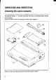
UNPACKING AND INSPECTION Checking the carton contents Now unpack the contents of the shipping carton, and check each item in the box against Figure l-l to make sure that you have everything (there should be six items). If any of these items are missing, contact your supplier. Figure T-l.Checktomakesureyou haveall sixitems: 1) Printer.2) Paperguide,3) RolleruniL4) 5) Ribbon cartridge, and 6) Manual set (User’s manual, User’s guide and Sticker).
The optional accessories which you may have ordered with your printer are: l Font cartridges (FC-lZ, FC-2Z, FC-3Z, FC-4Z) l RAM cartridge (RC-32Z) l Serial-Parallel converter (SPC-8K) l Automatic sheet feeder (SF- 1ODQ) l Roll paper holder (RH-IOZ) /den tifying printer parts Make an external inspection of the printer. Note the locations of the following parts in Figure l-2. Figure 7-Z.
SETTING UP Place the printer in the desired location, and remove all packing material from inside the top cover. This packing material is intended to prevent damage to the printer while in transit. You will want to keep all the packing material, along with the printer carton, in case you have to move the printer to a new location. Mounting the platen knob The platen knob is packed into a recess of the packing material which held your printer inside the carton. Be sure to remove the knob from the packaging.
Figum 1-4. Removing the top cover 1. Turn the tension knob clockwise on the ribbon cartridge to tighten the ribbon if it is slack. 2. Guide the ribbon between the print head and the silver print head shield, making certain that the spindles on the cartridge holder fit into the sockets on the cartridge itself. Figutu T-5.
3. The ribbon should pass between the print head and the print head shield (see Figure 1-6). I Figure I-6. Pass the ribbon between the print head and print head shield 4. After you have installed the ribbon cartridge, install the roller unit. 5. Open the rear cover using the two pits on either side. 6. Gripping the lock levers on both sides of the roller unit, fit the mounting brackets onto the shaft inside of the printer mechanism. You will need to tilt the roller unit slightly backward. 7.
Hgure 1-7. Install the roller unit onto the printer To replace the top cover, insert the tabs into the slots on the printer case. Swing the front edge down to close the cover. Leave the top cover closed during normal operation. The cover keeps out dust and dirt and reduces the printer’s operating sounds. Open the cover only to change the ribbon or make an adjustment.
Ins falling the optional cartridge This printer has five built-in LQ fonts, and a 7 K-byte (30 K-byte for color printer) printing buffer. You can add more fonts or expand the printing buffer by installing optional cartridges (Font catridge or RAM cartridge). To install or change a cartidge, follow the procedure below. 1. Turn off the power switch at the front of the printer, and remove the top cover. 2. Remove the connector cover at the right side of the printer. 3.
Connecting the printer to your computer Connect the printer to your computer using a standard parallel interface cable. On a PC or PC/AT-type computer, this means that you use the 25-pin D-type connector at the computer end, and the Amphenol-type 36pin connector at the printer end. The configuration of the printer’s connector is given in Chapter 8 should you need a cable for connection to another computer. If you need to connect to a serial port, use the optional Serial-Parallel converter, SPC-8K.
LOADING SINGLE SHEETS This section will take you through the procedures for loading single sheets of paper. If you are using the optional automatic sheet feeder (SF-lODQ), refer to the ASF instruction booklet. Automatic loading Single sheets can be loaded manually with the power off, or automatically with the power on. We will start the easy way with automatic loading. 1.
4. Make sure that the release lever is back. If fanfold paper is already mounted in the printer, press the ( SETpkEillp button to park the paper in the off-line state, then move the release lever backwards. 5. Place a single sheet between the guides, placing the side on which you want to print towards the back of the printer. Gently push the paper down in the guides until you feel it stop. 6. Now press the ( SE&/f&CT ) button.
Manual loading It is also possible to load paper manually while the printer’s power is off. The procedure is: 1. Place the paper guide in position by inserting the tabs, located on the bottom of the assembly, into the slots on the rear cover of the printer. 2. Check that printer power is off and the release lever is back. 3. Adjust the paper guides to match the size of paper you will be using. Remember that printing will start some distance from the left-hand edge of the carriage. 4.
LOADING AND PARKING FANFOLD FORMS Fanfold forms have holes along the sides and perforations between the sheets. They are also called sprocket forms, punched forms, or just plain “computer paper”. This printer accepts forms up to 10” wide. This section will take you through the procedures for loading, parking and unparking fanfold forms. NOTE: To get good line-feeding, put l-inch space (non-printing area) around a perforation. .
6. Move the tractor units downwards by gripping the positioning levers on both side of the tractor unit as shown in Figure 1-13. Figure T-73. Move the tractor units downwards for loading the paper from the rear 7. With the tractor covers open, mount the paper by aligning holes with the pins on the tractor unit. lamp level FigUf.9 14 1-14. Mount the tantold paper over the tractor units.
8. Adjust the spacing of the tractor units by sliding them along the bar, using the clamp lever at the back of each unit to release and lock them in position. When the clamp lever is up, the unit is released, and when it is down, the unit is locked. 9. Now close the tractor covers, again making sure that the paper holes are aligned with the pins on the tractor units. If they are not aligned properly, you wilI have problems with paper feeding, possibly resulting in tearing and jamming of the paper. 10.
Loading the paper from the bottom of the printer You can load the fanfold paper from the bottom of the printer with the following procedure. 1. Remove the top cover and the roller unit. 2. Open the rear cover using the two pits at the side, and push backwards. 3. Grip the positioning levers on both side of the tractor unit, and pull the unit upwards as shown in Figure l-l 6. Figure l-16. Pull up the tractor unit for bottom feeding 4. Place a stack of fanfold paper below the printer. 5.
Figure 7-77. Install the roller unit after mounted the fanfold paper from the bottom of the printer. 7. Now close the tractor covers, again making sure that the paper holes are aligned with the pins on the tractor units. If they are not aligned properly, you will have problems with paper feeding, possibly resulting in tearing and jamming of the paper. 8. Remount the roller unit and replace the rear cover and the top cover.
I button on the control panel. 4. Press the ( 5E’phE&C’ The printer will automatically feed the fanfold form backward until the paper is completely free of the platen. 5. Move the release lever to the back. 6. Mount the paper guide in the upright position. Now you can load single sheets either automatically or manually, as explained previously. The fanfold paper remains parked at the back of the printer. NOTE: You cannot park the fanfold paper if you have loaded it from the bottom of the printer.
LOADING MULTI-PART FORMS You can print on continuous multi-part forms with the built-in tractor unit. You can use multi-part forms that have up to five parts including the original when the Multi-part mode is selected with the EDS setting. (For details, please refer to Chapter 3.) It is recommended to use forms jointed by dotted orpasting under the normal office condition. L Multi-part forms should be pressure sensitive, and should not be used in the friction feed.
ADJUSTING THE PRINTING GAP The distance between the print head and the platen can be adjusted to accommodate different paper thicknesses. To make this adjustment, remove the top cover. The adjustment lever is located at the left side of the printer mechanism. Pushing the adjustment lever backwards narrows the gap; pulling it forwards widens the gap. There are six positions, and you can feel the lever clicking into each position.
The following table provides the recommended lever positions for each paper types as a reference. Weight (g/m2) (Each paper) Thickness (mm) Recommended (Total) Lever position 52 - 82 0.07 - 0.10 2nd 83-90 0.11 - 0.12 3rd 2-PlY 40 - 58 0.12 - 0.16 3rd 0.18 - 0.20 3rd 3-PlY 40-58 0.21 - 0.25 4th 4th 40 - 58 0.24 - 0.26 4-PlY 0.27 - 0.30 5th Paper Type Single 5-PlY 40-58 0.30 - 0.33 0.34 - 0.35 1 5th 6th NOTE: Pressure sensitive paper is recommended for the multi-part paper.
MEMO
Chapter 2 CONTROL PANEL OPERATIONS The control panel buttons can be pressed individually to perform the operations indicated by their names. Other functions can be achieved by holding these buttons down when you turn the printer’s power on, or by pressing the control panel buttons in combination. This chapter explains all the button and indicator functions.
ON LINE button The ( ONLINE ) button sets the printer on-line and off-line. The status changes each time you press the button. When the printer is on-line, it can receive and print data from the computer. When the printer is off-line, it stops printing and sends the computer a signal indicating that it cannot accept data. The printer powers up in the on-line status if paper is loaded, If paper is not loaded, the printer powers up off-line with the POWER indicator flashing.
If you alSO press the ( ON LINE ) button while you are line-feeding, t.he paper will feed automatically to the top of the next page. This is explained later. If you press this button while on-line, this will alternately flash the QUIET indicator on and off. When in Quiet mode with the QUIET indicator lit, the printer will print slightly slower, but at a reduced noise level. SET/EJECT/PARK button NOTE: This button has no effect if the bottom feed mode is selected.
FONT button This button selects the font to be printed. Draft font is selected at power-up unless the default settings are changed. To change to HS Draft (High-Speed Draft) or one of the LQ (Letter Quality) fonts, set the printer off-line, then press the CFONt, button repeatedly until the indicators beside the desired selection illuminate.
POWER-UP FUNCTIONS In addition to their normal functions, all the control panel buttons have special functions that operate if you hold them down while switching power on. Badlrectmnal Test/Adjustment Figure Z-2. Power-up functions of control panel Short test mode If the printer is turned on while the c ONLINE 1 button is pressed, the printer will enter the short self-test mode. The printer will print the version number of the printer’s ROM, followed by seven lines of the character set.
I t Long test mode If the printer is turned on while the (PAPERFEED) button is pressed, the printer will enter the long self-test mode. The printer will print the version number of the printer’s ROM and the current EDS settings, followed by the whole character set printed in each font and pitch available. The test cycles endlessly, so you must turn the power off to stop it.
Since the self-test occupies the full width of the carriage, it is recommended that the printer is loaded with the widest paper possible to avoid damage to the print head and/or platen. In addition, the total number of lines printed is considerable, more than can be accomodated on a single sheet, so fanfold paper is recommended for this test. Print area test mode By holding the( SE&E&CT 1 button down during power-up, the printer will enter the print area test mode.
Hexadecimal dump This feature is useful for programmers who are debugging printing programs and want to see the actual codes the printer is receiving. (Some computers change the codes the programmer intended.) In this mode, all data received will be printed in a hexadecimal dump format, rather than the control codes being acted on as command codes. This mode is accessed with the following procedure: SEJ&l~“’ )buttons down, 1. While holding both the(PAPER FEED)and( turn power ON. A beep tone will be heard.
Most BASICS, however, are not quite that straightforward. For example, the IBM-PC will give you a printout similar to Figure 2-6. L.. 00 OF 20 30 40 50 60 01 10 21 31 41 51 61 02 11 22 37 42 52 62 03 12 23 33 43 53 63 04 13 24 34 44 54 64 05 14 25 35 45 55 65 06 15 26 36 46 56 66 07 16 27 37 47 57 67 08 17 28 38 48 58 68 09 58 29 39 49 59 69 OA 19 2A 3A 4A 5A 6A OB 1B 26 38 46 58 68 OC 1C 2C 3C 4C 5C 6C OD 1D 20 30 40 5D 60 OA 1E 2E 3E 4E 5E 6E OE 1F 2F 3F 4F 5F 6F . . . . . . . . . . . .
SWITCH COMBINATION FUNCTIONS Several additional functions can be achieved by pressing the control panel buttons in combinations. - Top of Form Figutu 2-7. Switch combination functions of control panel Form feed If you are using single sheets, this operation ejects the current page. If you are using fanfold forms, it feeds to the top of the next page. 1. Press the ( ON LINE 1 button to set the printer off-line. 2. Press the (PAPER FEED) button and hold it down.
3. Press and hold the ( ON LINE > button. 4. While holding the ( ON LINE )button down, press the (PITCH)button, then release both buttons at the same time. The printer will beep to indicate that the top-of-form position has been set. Forward micro-feed For fine alignment, you can feed the paper forward in very small increments as follows: 1. Press the ( ON LINE ) button to set the printer off-line. 2. Press the ( ON LINE ) button again and hold it down. 3.
This value will remain unless you power off the printer. If you want to retain this value even after you turn off the power, store it using the Macro Definition function, which is described below. Note that you can only change this value immediately after loading paper. If you feed paper, you cannot change the auto loading value. Clearing the buffer/All reset The printer stores received data in a large memory buffer.
Selecting the print color Normally, the color printer prints with black even if the color ribbon is installed. Without the aid of software, you can change the printing color as follows: 1. Press the ( ON LINE ) button to set the printer off-line. 2. Press the (FONT) button and hold it down. button, press the ( SLAd&’1 ) button. 3. While holding them button, one of the indicators of Each time you press the FONT or PITCH will blink to show the current color as shown below. 4.
l Current print color (color printer only) Data to be stored are controlled in Standard mode and IBM mode separately. For example, the data stored in the Standard mode are not effective in the IBM mode, and vice versa.
Chapter 3 DEFAULT SETTINGS Most printers use a bank of DIP (Dual In-line Package) switches inside the printer to achieve various functions. However, this printer can change the power-up default settings by using the Electronic DIP Switch (EDS) mode. This chapter explains how to use the EDS mode. HOW TO SET THE EDS MODE The EDS mode has 25 kinds of functions you can set as the power-on default.
FUNCTIONS OF THE EDS SElTlNGS The printer is factory-set with all EDS switches in the ON position. These are the standard settings. By changing the settings, you can alter various printer functions to match your requirements. The following questions will help you choose the proper settings.
Switch A-l: Do you want to use the printer in Standard mode or IBM mode? Select the mode compatible with your computer and software. In Standard mode the prinlcr operates like the Epson LQ-860. In IBM mode it operates like the IBM Proprintcr X24E. The ON position selects Standard mode. The OFF position selects IBM mode. Switch A-2: Does your software download characters to the printer? ‘..- In order to download characters this switch must be in the OFFposition.
Switch B-l: Are you going to print on multi-part paper? You can use up to 3-ply paper when this switch is ON. If you want to print on 4-ply or 5-ply paper, set this switch to the OFF position. Switch B-2: Do you want the printer to stop printing at the end of the paper, or to keep printing? When this switch is OFF the printer ignores the paper-out detector and prints down to (and beyond) the bottom edge. Otherwise leave it ON.
Switches C-3 and C-4: What is the page length of your paper? I j ( Leave these switches ON if you will bc using 1l-inch forms. You will need to change the switches if you will be using a different page length as shown below: Switch D-l: The action of this switch depends on the mode chosen with switch A-l. If you sclccted Standard mode, do you want italic or graphic characters? Move this switch OFF to print italics in the Standard character set.
Except in the Standard Italic character set, these switches select the default character code page as shown below: IBM Code Page D-2 D-3 D-4 IBM Code Page D-2 D-3 D-4 #437 U.S.A.
BIDIRECTIONAL TEST/ADJUSTMENT MODE This mode is used to adjust the alignment of the print head on successive bidirectional passes. After a period of some months, your printer may work itself out of alignment on left and right printing passes. This will be most evident in graphics printing. This mode will probably be used very rarely. 1. Turn the printer off and then turn it on again while holding down the “F;f&“’ > and ( ON LINE ) buttons.
6. To save the corrected values and to exit from this mode, press the ( button.
Chapter 4 PRINTER CONTROL COMMANDS The printer has two emulation modes: Standard mode and IBM mode. In standard mode, the printer emulates the functions of the Epson LQ-860. In IBM mode, the printer emulates the IBM Proprinter X24E. Additional command codes are included as a superset of these emulations. The emulation is changed by means of EDS switch A- 1. When ON, the printer will be in standard mode, and when OFF, the printer will be in IBM mode (see Chapter 3).
FONT CONTROL COMMANDS Select draft quality characters Mode Bo* Std. Decimal ASCII “(” “(3. “F” “)” “x” “X” co> “)” Hexadecimal 40 40 70 41 41 57 “9” “0” 28 28 46 29 29 39 27 120 48 18 78 30 27 120 18 0 78 00 Changes from letter quality to draft quality. Ignored if the (FONT) button was pressed during power-up.
Select L Q characters Mode Std. Hexadecimal Decimal ASCII “x” “1” “X1’ 27 120 49 1B 78 31 27 120 1B 78 01 1 Changes from draft quality to letter quality. The initial LQ font is Roman unless a different font has been selected by a preceding command. Ignored if the (FONT) button was pressed during power-up. Select LQ pica characters Mode ASCII IBM Decimal “I” <2> 27 73 Hexadecimal 2 1B 49 02 Changes to letter quality characters with pica pitch (10 cpi).
Select LQ proportional Mode ASCII IBM characters Hexadecimal Decimal “I” 27 73 <3> 3 18 49 03 Changes to letter quality characters with proportional pitch. Ignored if the m or (ml button was pressed during power-up. Select LQ font Decimal Hexadecimal Mode ASCII Both ‘I? n 27 107 n 18 6B n “C” n 28 67 n 1C n Std. 43 Selects an LQ font according to the value of n. In draft mode, this command remains dormant and takes effect later when LQ is selected.
Select italic characters Mode ASCII Std. Decimal Hexadecimal 27 52 “4” 1B 34 Causes subsequent characters to be printed in italics. Select upright characters Mode ASCII Std. Decimal Hexadecimal 27 53 “5” 1B 35 Stops italic printing and causes subsequent characters to be printed upright. Emphasized printing Mode ASCII Both Decimal Hexadecimal 27 69 “E” 18 45 Causes subsequent characters to be emphasized by adding extra thickness to vertical strokes.
Cancel double-s trike printing Mode ASCII Both Decimal “H” Hexadecimal 1B 48 27 72 Cancels double-strike printing. Start underlining Mode Both ASCII Decimal “-” ‘I-” “1” Hexadecimal 27 45 49 27 45 1 IB 2D 31 1B 2D 01 Causes subsequent characters to be underlined. IBM block graphics characters and spaces skipped by horizontal tabulation are not underlined.
Select score Mode Std. Hexadecimal Decimal ASCII “-” “(” CO7 cl7 27 40 45 <37 nl 0 n2 1 nl 3 1B n2 28 2D 00 03 01 nl n2 Start score according to the values of nl and n2, as shown below. nl 1 2 3 n2 0 1 2 5 6 Function Underlining Strike-through Overlining Function Cancel score Single continuous line Double continuous line Single broken line Double broken line Select ornament character Mode ASCII Std.
Subscript 1 Decimal IMode 1 ASCII Both “S” “S" “1” 1 Hexadecimal 27 83 49 1B 53 31 1 1B 53 01 27 83 Causes subsequent characters to be printed as subscripts. Does not change the character pitch. Cancel superscript Mode 1 or subscript ASCII Both I Decimal 1 27 84 “T” Hexadecimal I IB 54 Stops printing superscripts or subscripts and returns to normal printing. CHARACTER SET COMMANDS Select standard character set Selects the standard character set.
Select character set #I Mode ASCII Both Decimal 27 55 “7” Hexadecimal 1B 37 Selects character set #l. Select character set #2 Mode Both Decimal ASCII
Select IBM code page Mode Both ASCII Decimal “[” “T” <4> <0> nl n2 CO> CO> Hexadecimal 27 91 84 0 4 0 nl 0 n2 18 58 00 54 04 00 nl 00 n2 Changes the code page of the current IBM character set according to the values of nl and n2. nl n2 1 3 181 82 3 3 3 3 92 93 95 97 Code page #437 U.S.A. #850 Multi-lingual #860 Portuguese #86 1 Icelandic #863 Canadian French #865 Nordic These code pages can be selected as power-up defaults by EDS switches D-2 to D-4.
Select slash zero Mode Std. ASCII Decimal Hexadecimal “ _ ” “1” 27 126 49 1B 7E 31 "- " 27 126 IB 7E 01 <17 1 Causes subsequent zero characters to be overprinted with a slash (0). Select normal zero Mode Std. ASCII Decimal Hexadecimal “ - " "0" 27 126 48 IB 7E 30 “- ” 27 126 1B 7E 00 <()7 0 Causes subsequent zero characters to be printed normally (0), without a slash. CHARACTER SIZE AND PITCH COMMANDS Pica pitch Mode ASCII Std.
Semi-condensed Mode ASCII Std. pitch Decimal Hexadecimal 27 103 “g” 1B 67 Changes from either pica or elite to semi-condensed pitch (15 cpi). Ignored if the (PITCH)button was pressed during power-up. Condensed printing Mode Both ASCII Decimal
Expanded printing Mode Both for one line Decimal ASCII 14 27 Hexadecimal OE 14 18 OE Causes subsequent characters in the current line to be expanded to double width. Characters return to normal width after the next line feed (). The , , , and Decimal 20 Hexadecimal 14 Stops one-line expanded printing set with or
Select fixed spacing Mode Hexadecimal “p” “0” “p” 27 112 48 1B 70 30 27 112 0 1B 70 00 “P” 27 80 0 1B 50 Std. - IBM Decimal ASCII 00 Causes subsequent characters to be printed with fixed character spacing. Ignored if the(piK%“button was pressed during power-up. Select master print mode Mode ASCII Std. Decimal LL,.. . n 27 33 n Hexadecimal 1B 21 n Selects a combined print mode according to the value of n.
Select double or quadruple size Mode ASCII Std. Decimal “h” 27 104 n Hexadecimal n 1B 68 n Selects the size of subsequent characters as shown below. Extrahigh characters align along the cap-line of normal characters, with the base line temporarily moving down. Line spacing is temporarily doubled when n = 1 and quadrupled when n = 2.
Return to normal height Terminates double-height printing and prints subsequent characters at normal height. Select character height, width, and line spacing Mode IBM ASCII Decimal “[” “@” <4> <0> n m 27 91 64 0 0 Hexadecimal 4 0 1B 5B nm 00 40 00 04 00 n m Selects a combination of character height, width, and line spacing according to the value of n and m, as below. Does not move the base line.
VERTICAL POSITION COMMANDS Set line spacing to l/8 inch Mode ASCII Both Decimal Hexadecimal 27 40 “0” 1e 30 Sets the distance the paper advances or reverses in subsequent line feeds to l/8 inch. i ,. Set line spacing to 7160 or 7/72 inch Mode ASCII Both Decimal Hexadecimal 1B 27 49 “1” 31 Sets the distance the paper advances or reverses in subsequent line feeds to 7/60 inch (standard mode) or 7/72 inch (IBM mode). Set line spacing to l/6 inch Mode ASCII Std.
Set base unit for line spacing Mode IBM ASCII Decimal “[” ‘T’ <4> n Hexadecimal 27 91 92 0 0 4 0 0 1B 58 5C n 00 00 04 00 00 n Sets the base unit for the line spacing commands, cESC> “3” and “J”. If the value of n is 180, the base unit is set to l/l 80”. If the value of n is 216, the base unit is set to l/216”. If otherwise specified, this command is ignored.
Execute “cA” Decimal “2” 27 50 Hexadecimal 1B 32 Sets the line spacing to the value defined by the last preceding Decimal 10 Hexadecimal OA Prints the current line and feeds the paper to the next line. See the preceding commands for the line spacing. Reverse line feed Mode Decimal ASCII Hexadecimal Std.
Perform one n/l804nch or n/216=inch line feed Mode ASCII Both Decimal “J” 27 74 n Hexadecimal 1B 4A n n Feeds the paper once by n/l 80 inches or n/216 inches, where n is between 1 and 255. Does not move the print position right or left in the standard mode. Does not change the line-spacing setting. Perform one n/180-inch reverse line feed Mode ASCII Std.
Set page length to n inches Mode ASCII Both cESC> Decimal “C” -co> Hexadecimal 27 67 n 0 1B 43 00 n n Sets the page length to n inches, where n is between 1 and 32 in Standard mode or between 1 and 64 in IBM mode. The current line becomes the top of the page. Set bottom margin . .. Mode 1 I ) ASCII t Both 1 I “N” n Decimal 1 27 70 )I n Hexadecimal IlB4E 1 n Sets the bottom margin to n lines, where n is between 1 and 127 in Standard mode or between 1 and 255 in IBM mode.
Return to top of current page Mode Std. ASCII Decimal Hexadecimal 27 12 1B OC Feeds the paper backward to the top of the current page. Ignored when friction feed is used. Disable paper-out detector Mode ASCII Both Decimal Hexadecimal 27 56 “8” 1B 38 Causes the printer to disregard the signal sent by the paper-out detector, enabling printing to the bottom of the paper.
Set vertical tab stops every n lines Mode Std. Hexadecimal Decimal ASCII “e” “1” n 27 101 49 n 1B 65 31 n “e” cl> n 27 101 n 1B 65 01 n 1 Cancels all current vertical tab stops and sets new tab stops every n lines, where n is between 2 and 127. Set vertical tab stops in channel Mode Std. Decimal ASCII “b” n0 n2 nl .. . 27 98 no nl n2 . 0 Hexadecimal 1B 62 n0 n2 nl ...
HORIZONTAL POSITION COMMANDS Set left margin Mode ASCII Std.
Set left and right margins [Mode 1 ASCII 1 IBM 1 “X” nl n2 1 Decimal 1 127 IlB 88nln2 Hexadecimal 1 58&d 1 Sets the left margin at column nl and the right margin at column n2. See the preceding commands for margin restrictions and other notes. Carriage return Mode ASCII Both Decimal Hexadecimal 13 OD Prints the current line and returns the next print position to the left margin. If EDS switch A-3 is OFF, also performs a line feed.
Left justify Mode Std. ASCII Decimal “a” “0” 27 97 48 18 Hexadecimal 61 30 “a” CO> 27 97 iB 61 0 00 Aligns subsequent text with the left margin, leaving the right margin ragged. Center text Mode Std. Decimal ASCII “a” “1” “a” cl> Hexadecimal 27 97 49 IB 61 31 27 97 1B 61 01 1 Centers subsequent text between the left and right margins. Right justify Mode ASCII Decimal Hexadecimal Std.
Set horizontal tab stops Mode Both Decimal ASCII “D” nl n2 ... -CO> Hexadecimal 27 68 nl n2 .. . 0 1B 44 nl n2 ,..00 Cancels all current horizontal tab stops and sets new tab stops at columns nl, n2, etc. in the current character pitch (pica pitch if proportional spacing is currently selected), where nl, n2, etc. are numbers between 1 and 255. The maximum number of horizontal tab stops allowed is 32 in Standard mode and 64 in IBM mode.
Relative horizontal tab Mode ASCII Std. Decimal ‘T’ nl 27 92 nl n2 Hexadecimal IB 5C nl n2 n2 Moves the print position right or left a specified distance (maximum 8 inches). Ignored if the resulting position is beyond the right or left margin. The formulas for the distance and direction are as follows: If n2 is between 0 and 63, the print head moves right by (nl + n2 x 256) dots.
GRAPHICS COMMANDS Print normal-density g-bit graphics Mode Both ASCII Decimal “K” nl ml n2 m2 . .. Hexadecimal 27 75 nl n2 ml m2 . . . IB 48 nl n2 ml m2 . . Prints bit-image graphics at 60 dots per inch horizontally. The graphic image is 8 dots high and nl + n2 x 256 dots wide. Maximum width is 8 inches (480 dots). ml, m2, ... are the dot data, each a lbyte value from 0 to 255 representing 8 vertical dots, with the most significant bit at the top and the least significant bit at the bottom.
Print hex-density 24-bit graphics Mode Std. Decimal ASCII “Z” ml nl m2 n2 m3 .. . 28 90 nl ni? ml m2 m3 . Hexadecimal 1C 5A nl ml m2 d m3 .. . Prints 24-bit dot graphics at 360 dots per inch horizontally. The graphics image is 24 dots high and nZ + n2 x 256 dots wide. Maximum width is 8 inches (2880 dots). In the data ml, m2, m3 .. . each three bytes represent 24 vertical dots.
Seiecf graphics mode Mode IBM Decimal ASCII “[‘I “g” nl m0 ml m2 n2 .. . Hexadecimal 27 91 103 nl n2 m0 ml m2 .. . iB 58 67 nl n2 m2 .. . m0 ml Selects one of eight graphics modes depending on the value of m0 and prints dot graphics in this mode. The graphics image is (nl + n2 x 256) - 1 dots wide. See “K” (for g-bit graphics) or “Z” (for 24-bit graphics) for information on ml, m2, ...
DOWNLOAD CHARACTER COMMANDS Define download characters Mode Std. ASCII Decimal “8~” nl n2 m0 ml m2 dl d2 27 38 n2 dx dl Hexadecimal 0 nl m0 ml m2 d2 . . . dx 16 26 00 nl n2 m0 ml m2 dl d2 . dx Defines one or more new characters and stores them in RAM for later use. EDS switch A-2 must be OFF; otherwise RAM is used as an input buffer, not downloading characters, and this command is ignored.
Define download characters Decimal ASCII “='I nl n3 n2 n4 "#" dl m9 d2 “’ .. . Hexadecimal 35 n?n4 On5 mlm2 ...m9 n5 m2 ml 27 61 nl n2 ak dl d2 a5 1B 3D nl nl 23 n3 n4 00 n5 ml m2 . m9 dl d2 dx Defines new characters and stores them in RAM for later use. EDS switch A-2 must be OFF and the optional RAM cartridge, RC-32Z, must be installed; otherwise RAM is used as an input buffer, not downloading characters, and this command is ignored.
dl, d2, .. . dr is the Dot Pattern data being downloaded. Each data byte indicates eight vertical dots, with the most significant bit being the top dot, and the least significant bit being the bottom dot. Copy character set from ROM into RAM Mode ASCII std. Hexadecimal Decimal Y’ CO> n co> 27 56 0 n 0 lB3AOO nOO Copies the selected character set with n, as shown below, to the corresponding download character RAM area, overwriting any download data already present.
Select draft pica download character set Mode ASCII IBM Hexadecimal Decimal “I" <4> 27 73 4 1B 49 04 Selects the download character set, draft quality, and pica pitch (1Ocpi). Ignored if the (FONT) button was pressed during power-up or if EDS switch A-2 is ON. Select draft elite download character set ‘. ^_ Mode IBM ASCII Decimal 27 73 12 “I” Hexadecimal 16 49 oc Selects the download character set, draft quality, and elite pitch (12 cpi).
Select L Q elite download characters Mode ASCII IBM Decimal “I” 27 73 14 Hexadecimal 1B 49 OE Selects the LQ download character set with elite pitch (12 cpi). Ignored if the -button was pressed during power-up or ifEDS switch A-2 is ON. Select LQ condensed download characters Mode ASCII IBM Decimal “I” 27 Hexadecimal 73 22 1B 49 16 Selects the LQ download character set with condensed pitch (17 cpi).
I‘2 1 f COLOR SELECTION COMMANDS The commands in this section are valid only with the color printer. Select print color Mode Both ASCII ( 1. 9, ‘I( 31 UC.9 “I” Hexadecimal Decimal “)” “)” n n 40 40 67 41 41 n 20 26 43 29 29 n 27 114 18 n 72 n Selects the printing color according to the value of n as shown below. Ignored if the color ribbon is not installed.
Accept MSB as is Mode ASCII Std. Decimal Hexadecimal 27 35 “#” 1B 23 Cancels the preceding commands and accepts the most significant bit as it is sent to the printer. Delete last character sent Mode 1 Decimal ASCII 1127 Std. I Hexadecimal 1 7F Deletes the last character received. Ignored if the last character received has already been printed, or if the last character received was all or part of a command.
Stop printing Mode ASCII IBM Decimal 27 ‘j” Hexadecimal 106 IB 6A Prints the entire contents of the input buffer, then sets the printeroffline. The ( ONLINE > indicator on the control panel goes off. Bell Mode Both Decimal ASCII Hexadecimal 7 07 Sounds a brief beep tone from the printer’s beeper.
Manual feed I IMode 1 ASCII Both u(,. 27 25 <0> “0" ,,(,, Decimal ‘3" ‘3" 1 40 40 1 Hexadecimal 0 1B 48 41 41 1 28 ) 19 00 28 30 29 29 Selects manual sheet feeding even when the optional automatic sheet feeder is mounted. Ignored if EDS switch A-4 is ON (ASF inactive). Auto feed Decimal ASCII Mode Bo* 27 25 <4> “(9, “(” "4" “)" ")" 40 40 Hexadecimal 4 52 41 41 IB 19 04 28 28 34 - 29 29 Selects the automatic sheet feeder.