PRESENTER UNIT PR921-24-A SPECIFICATION MANUAL
NOTICE • All rights reserved. Reproduction of any part of this manual in any form whatsoever, without STAR’s express permission is forbidden. • The contents of this manual are subject to change without notice. • All efforts have been made to ensure the accuracy of the contents of this manual at the time of going to press. However, should any errors be detected, STAR would greatly appreciate being informed of them. • The above notwithstanding, STAR can assume no responsibility for any errors in this manual.
CONTENTS 1. GENERAL DESCRIPTION ................................................................................................................ 1 1.1 Model Name Display Directions ............................................................................................. 1 2. PRINTER CONFIGURATION ........................................................................................................... 2 3. PAPER SPECIFICATIONS (HEAT SENSITIVE PAPER) ..................................................
1. GENERAL DESCRIPTION The PR921 is a paper (receipts, etc.) discharging device that uses a built-in thermal printer system employed in electronic devices such as game machines, ATM and unmanned information kiosk terminals, etc. This model carries a paper (receipts, etc.) recovery function after discharge, as a standard. 1.
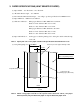
2. PRINTER CONFIGURATION The presenter mechanism is composed of the following devices.
3. PAPER SPECIFICATIONS (HEAT SENSITIVE PAPER) (1) Paper Width : 79.5 ±0.5 mm to 111.5 ±0.5 mm (2) Allowable Sheet Length : 75 to 300 mm (3) Recommended Heat Sensitive Paper : According to product specifications for TMP942-24-A. (4) Paper Thickness : 0.065 mm to 0.150 mm (5) Shaft Core Diameter : When paper thickness is Min. 0.065 mm to 0.10 mm Shaft core inner diameter: Min. 25.4 ±1 mm; Shaft core outer diameter: Min. 31.4 ±1 mm When paper thickness is Min. 0.10 mm to 0.
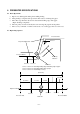
4. PRESENTER SPECIFICATIONS 4.1 Basic Operations a. Paper is not discharged from the printer while printing. b. After printing is completed, the presenter roller rotates to discharge the paper. c. The roller stops when the detector has detected the trailing edge of the paper. (Paper discharge completed) d. The next print job can be started by the user removing the paper from the printer. e. The recovery command or a timer can be used to recover the paper if it is not removed. 4.
(1) Paper is discharged and the trailing edge of the paper is stopped in front of the PF roller. Presenter Inlet Presenter Outlet Paper Position 200 ms CW 2 DC Motor CCW 4 Terminal Shorted and Motor Stopped ON Sensor 1 1 OFF ON Sensor 2 3 OFF Sensor 3 1 2 3 4 No Discrimination Sensor 1 detects leading edge of paper and sensor 1 turns ON. Sensor 1 turns ON, DC motor starts rotating clockwise. Sensor 2 detects leading edge of paper and sensor 2 turns ON.
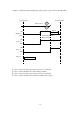
(2) Paper Discharge Until Paper Trailing Edge is Stopped Before PF Roller Presenter Inlet Presenter Outlet Paper Position CW DC Motor 200 ms 5 8 CCW 7 Terminal Shorted and Motor Stopped ON 6 Sensor 1 OFF ON Sensor 2 OFF Sensor 3 5 6 7 8 No Discrimination DC motor rotates clockwise by the paper discharge instruction. Sensor 1 detects trailing edge of paper and sensor 1 turns OFF. Sensor 1 turns OFF, paper is fed 1.2 mm. After feeding paper 1.2 mm, DC motor is braked for 200 ms and stopped.
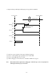
(3) Paper Recovery Operation If the sensor 2 and sensor 3 detection signals are ON after a determined amount of time has passed, the paper recovery operation is performed. Presenter Outlet Presenter Inlet Paper Position 1s CW DC Motor 9 200 ms 12 CCW Terminal Shorted and Motor Stopped ON Sensor 1 OFF ON 11 Sensor 2 OFF ON Sensor 3 10 OFF 26 ms Sensor 3 turns OFF, then, if sensor 2 turns OFF, it is determined that the paper has been recovered.
4.3 Paper Detector General Specifications The paper detector is composed of a reflective sensor and generates a set/reset signal.
4.4 Presenter Motor General Specifications Model: Rated Voltage: Voltage Range for Use: Peak Current: Average Current: Mabuchi Motor FK-180SH 24.0 V 21.6 V to 26.4 V (24.0 V ±10%) Approximately 1.0 A (24 VDC, 25°C) Approximately 0.2 A (24 VDC, 25°C, including at startup.) Current (A) Time (T) Usage Temperature Range: No Load Current: No Load Revolutions: Rated Load Current: Rated Load Revolutions: Direction of Rotation: DC Motor Drive Speed Control: Drive and Control: Brake Control: -15°C to +60°C Max.
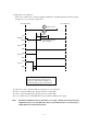
4.5 Connector 4.5.1 Paper Detector and Motor Connector 2 Presenter Intermediate Board 8 + 8 7 7 6 6 5 5 Connector 2 Pin #8: GND Black Pin #7: Sensor 3 Detection signal Black 8 7 DC Motor Sensor PCB 330 Ω Sensor 3 GP2S40J Sensor PCB 330 Ω Sensor 2 4 4 3 3 2 2 1 1 Pin #6: Motor(+) Black Pin #5: Motor(-) Black Pin #4: Sensor 2 Detection signal Black Pin #3: GND Black Pin #2: Sensor 1 Detection signal Black Pin #1: +3.
VM 4.5.2 Example Circuit B8B-PH-K-S 7 TA8428K VCC 1 PRM1 PRM2 2 VDD: 3.3V HS601 5 6 6 GND 4 10K VDD: 3.3V 8 2 4 7 HS601 R VDD: 3.3V 0R 4.7K PRS1ADJ VDD: 3.3V VDD: 3.3V 10K 3 2 PRS1 - 4 + 5 HA1 7339 M-GND 68K C 12 VDD: 3.3V 0.022U 0.1U 10K 2 1 3 GND VR_4.7K 0R 4.7K GND GND GND R VDD: 3.3V 4.7K PRS2ADJ 10K VDD: 3.3V 1 PRS2 6 HA1 7339 7 + 68K C 0.1U VDD: 3.3V 10K 2 1 3 GND VR_4.7K 0R 4.7K GND GND R VDD: 3.3V PRS3ADJ VDD: 3.3V PRS3 4.
5.
✽✵✲✻ ✸✼ ✵✺✼✲✸ ✵✷✴ ✸✼ ✻✺✲✻ ✵✶✲✹ ✼ ✹✻ ✻✹ ✹✼ ✻ ✹✼ ✹✻ Unit: mm Figure 5-1 – 13 –
Figure 5-2 – 14 – Motor Paper Detector Motor Motor Rear Guide Paper Detector Rear Guide Paper Detector
6. AMBIENT SPECIFICATIONS (1) During Operation Ambient Test (For Evaluation) Room Temperature : High Temperature : High Temperature/High Humidity : Low Temperature : Specifications Temperature : Humidity : (2) At Storage Storage Test (At Evaluation) High Temperature Storage : Low Temperature Storage : Humidity at Storage : Specifications Temperature : Humidity : 23°C at 50% RH 50°C 37°C at 85% RH 0°C 0°C to 50°C 10% to 80% RH (No condensation) However, 80% RH assumes 34°C.
7. RELIABILITY SPECIFICATIONS (1) Life Presentation System: 1 million times Note 1: If not using our recommended paper type, reliability cannot be guaranteed. Therefore, you should always use the recommended paper type. Note 2: This reliability is guaranteed for receipt lengths of 100 mm or less.
8. SETTING PAPER AND USING THE ACCESSORIES 8.1 Setting Paper (See Figure 8-1) 1) Cut the leading edge of paper to be set straight across the end. 2) Insert the paper straight along the paper mounted thermal mechanism and between the presenter paper guide and paper holder. 111.5±0.5 mm 79.5±0.
8.2 Using the Accessories (Weight Shaft and Loop Guide) • Paper thickness: Min. 0.065 to Max. 0.10 mm. (See Figure 8-2) 1) No shaft is used so fasten the 3 hooks in the 3 positions on the rear guide so that they do not get lost. 2) Fasten the loop cutter to the cutter with the 2 accessory screws. 1. Position the loop guide and cutter in positioners 1 and 2. 2. Tighten the screw next to the positioner 1. 3.
3) Rotate the paper holder and set after checking that it does not interfere with the loop guide. Note: Floating therebetween the cutter can occur because of deformation in the loop guide caused by sudden environmental changes. (See fig. 8-3) If that should occur, follow the directions above for the mounting of the loop guide and remount it so that it does not float.
• Paper thickness: Min. 0.10 to Max. 0.15 mm. (See Figure 8-4) 1) Fasten the shaft with the left and right hooks positioned on the Paper Holder. 2) Check that the shaft is securely fastened to the Paper Holder hooks to set it. Note 1: The 2 positions of the Paper Holder should be adjusted for the thickness of the recording paper, the length thereof and the environment of use. Note 2: The loop guide is not used, so store it so that it will not get lost.
9. RECOVERING FROM ERRORS (PAPER JAMS) Remove jammed paper according to the directions shown in Figure 9-1 and 9-2 to recover from non-recoverable paper jams. When doing so, always verify that the power has been turned OFF. (Procedure 1) 1) Rotate the knob in the clockwise or counterclockwise direction. 2) Remove the jammed sheet from where it is easiest to remove.
(Procedure 2: When Paper Cannot be Removed with Procedure 1) 1) Remove the screws on both sides of the presenter, shown in the figure below. 2) Rotate the rear guide and remove the jammed paper. 3) After removing the jammed paper, reverse the procedure 2), then fasten the screws in their original positions. Note: When fastening the screws in procedure 3), be careful not to pinch the wires shown in the figure below. Rear Guide Rear Guide Rotate Rotate Wires Screw: TAT 2.6 FC-06.0 FP Screw: TAT 2.
10. PRECAUTIONS REGARDING OUTER COVER DESIGNS To prevent jams at the presenter discharge outlet, consider designing the casing so that recording paper does not enter between the presenter unit and the case. 1 Gap of *1 must be a maximum of 1 mm. (See Figure 10-1) 2 The dimensions of *2 must be larger than the presenter discharge outlet (2 mm), but it should be small enough that it does not block the paper discharge outlet.(See Figure 10-1) If it is too large, interfering light (from the sun, etc.
Mechanism Presenter Depth: Max. Approx. 100 mm Figure 10-2 – 24 – Allow for plenty of space.
11. MAINTENANCE Perform the following maintenance periodically. Maintenance Periods: Every six months or after a million lines of printing. Location of Maintenance: Each detector and the vicinity Content of Maintenance: Clean away and paper dust or dirt and dust adhering to the detectors in the presenter. Note 1: Note 2: Always verify that the power supply has been turned OFF when performing maintenance on the presenter.
12. HANDLING THE PRESENTER 12.1 Precautions in Handling 1) Do not store or use the printer in locations that are dusty, oily or exposed to metallic dust. 2) Do not apply an unreasonable amount of force on the body. (This can disfigure the frame and lead to the printer not functioning properly.) 3) Avoid sudden changes even if the ambient temperature and humidity are within standard conditions.
Max.5° Max.
ELECTRONIC PRODUCTS DIVISION STAR MICRONICS CO., LTD. 536 Nanatsushinya, Shimizu, Shizuoka, 424-0066 Japan Tel : 0543-47-0112 Fax: 0543-48-5013 OVERSEAS SUBSIDIARY COMPANIES STAR MICRONICS AMERICA, INC. 1150 King Georges Post Road, Edison, NJ 08837-3729 U.S.A. Tel : 732-623-5555 Fax: 732-623-5590 http://www.starmicronics.com STAR MICRONICS U.K. LTD. Star House, Peregrine Business Park, Gomm Road, High Wycombe, Bucks, HP13 7DL, U.K. Tel : 01494-471111 Fax: 01494-473333 http://www.starmicronics.co.