Thermal Printer TSP200 Series Programmer’s Manual
TABLE OF CONTENTS 1. OUTLINE .............................................................................................. 1 2. MEMORY SWITCH AND DIP SWITCH ........................................... 2 2-1. Memory Switch ............................................................................ 2 2-2. DIP Switch ................................................................................... 2 3. DISPLAY PANEL AND FUNCTIONS ............................................... 4 3-1. LED ..................
1. OUTLINE The TSP200 series is ideal for printing text, bar code and graphics. The TSP200 series has the following features: 1. extremely quiet and fast printing (maximum 50 mm/sec.) using the direct line thermal printing method 2. support many bar code types (UPC-A, UPC-E, JAN/EAN-8, JAN/EAN-13, CODE 39, IFT 2 OF 5, CODE 128, CODE 93, NW-7) 3. dual interfaces (RS232C, Parallel) 4.
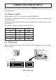
2. MEMORY SWITCH AND DIP SWITCH Functional settings are made using the printer’s EEPROM memory switches and the DIP switches. 2-1. Memory Switch Each memory switch is a 16-bit word stored in EEPROM. The printer is shipped with the factory setting which is made in accordance with its product type. For the detailed functions and the settings of the Memory switches, please refer to “Chapter 8”. The factory settings are shown in the table below.
DIP switch #1 The factory settings of DIP switch 1 are all on. Switch 1-1 1-2 1-3 1-4 1-5 1-6 1-7 1-8 Contents Baud Rate ON Data Length Parity Check Parity Selection Handshake Operating Mode Interface Baud Rate 2400BPS 4800BPS 9600BPS 19200BPS 8 bit Disabled Odd DTR Star RS232C 1-1 OFF ON ON OFF OFF 7 bit Enabled Even XON/XOFF ESC/POS Parallel 1-2 OFF OFF ON ON DIP Switch #2 Factory settings: 2-1 and 2-2 are on; 2-3 and 2-4 are off.
3. DISPLAY PANEL AND FUNCTIONS 3-1. LED LED POWER ON LINE Function Lights up when the printer is turned on. Blinks when an error occurs (Refer to 7. ERRORS.) Lights up when the printer is on line; goes off when the printer is off line or error occurs (Refer to 7. ERRORS.) 3-2. Switches Switch ON LINE FEED Function Switches between on line and off line Feeds the paper while pressed 3-3.
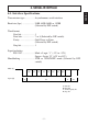
4. SERIAL INTERFACE SERIAL 4-1. Interface Specifications Transmission type ................. Asynchronous serial interface Baud rate (bps) ..................... 2400, 4800, 9600, or 19200 (Selected by DIP switch) Word format Start bit: ......................1 Data bits: ....................7 or 8 (Selected by DIP switch) Parity: ......................... Odd, Even, or None (Selected by DIP switch) Stop bit: ......................1 Signal polarities RS-232C .....................
4-2. Interface Circuit 4-2-1.
4-3. Connectors and Signal Names 1 SERIAL 5 6 9 4-3-1. RS-232C Interface Pin No. 1 2 3 4 Signal name FG RXD TXD DTR Direction – IN OUT OUT Function Frame ground Receiving data Transmission data ESC/POS mode 1) DTR/DSR communication mode Indicates if printer is busy or not. Space: Printer ready Mark: Printer busy The conditions for busy will vary according to the memory switch settings. Printer Status Memory SW #4-4 1 0 1.
Pin No. Signal name Direction SERIAL 5 6 SG DSR — IN 7 8 RTS INIT OUT IN 9 FAULT OUT Function Star mode Data terminal ready signal. When the printer is ready to receive data, this signal changes to “SPACE”. Signal ground Signal line that indicates whether the host can receive data Space : Host can receive data Mark : Host cannot receive data Does not confirm the status of this signal in XON/ XOFF communication or STAR mode.
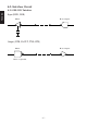
Refer to the host computer’s interface specifications for details of how to connect the interface. The following illustrations show typical connection configurations.
4-5. Data Protocol 4-5-1. DTR mode SERIAL This mode is accessed when the DIP switch 1-6 is set to ON. Signals are controlled using the DTR line as a BUSY flag. Data RXD Buffer full Data Data Buffer empty DTR Printing Power ON Immediately after power on (provided that no error occurs), the printer sets DTR to “SPACE” to indicate that it is ready to receive data. When the host detects that DTR is in “SPACE” condition, it begins sending text data over the RXD line.
Upon detecting an error, the printer immediately sets DTR to “MARK” and goes offline. If the error was caused by a paper-out condition, you can clear it by loading new paper and then pressing the ON LINE switch (Star mode) or closing the cover (ESC/POS mode). When paper is out RXD OFF LINE ON LINE DTR Printing Paper out PAPER OUT signal Power ON – 11 – Press the ON LINE switch after loading paper (Star mode).
4-5-2. X-ON/X-OFF mode This mode is accessed when DIP switch 1-6 is set to OFF. SERIAL X–OFF X–OFF X–OFF X–ON X–OFF X–OFF X–OFF X–ON X–ON TXD RXD Data Data Data Printing PAPER OUT signal ON ON LINE indicator OFF Power ON Paper out Load paper and press the ON LINE switch (Star mode). Immediately after power on (provided that no error occurs), the printer informs the host that it is ready to receive data by outputting the X-ON signal (control code DC1; value = 11H) over the TXD line.
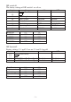
5. PARALLEL INTERFACE Interface: Data transfer speed: Synchronization: Handshaking: Logic level: Conforms with Centronics parallel interface standard 1000 ~ 5000 CPS External strobe pulse Using ACK and BUSY TTL-level compatible 5-2. Interface Timing ACK Approx. 9ms DATA STROBE T BUSY T T T: At least 0.5ms – 13 – PARALLEL 5-1.
Signal Name Sample Circuit 4.7kW DATA 1 ~ 74LS-equivalent Input DATA 8 1kW PARALLEL 100W STROBE 74LS-equivalent 1000pF Output 1.8kW BUSY ACK 74LS-equivalent 5-3. Connectors and Signal Names (18) (1) Conforms to Amphenol connector 57-30360 (36) (19) (Printer Side) Figure 5-1.
Signal name STROBE Direction IN 2-9 DATA 1~8 IN 10 ACK OUT 11 BUSY OUT 12 PAPER OUT OUT 13 SELECTED OUT 14-15 16 17 18 19-30 N/C SIGNAL GND CHASSIS GND +5V TWISTED PAIR RETURN 31 RESET IN 32 ERROR OUT 33 34-35 36 EXT GND N/C – – Function Strobe pulse for data read. Usually HIGH; goes LOW to trigger data read. Parallel data lines for eight-bit data. HIGH is “1”; LOW is “0”. Printer outputs this pulse for approximately 9µs to indicate that data read is completed.
6. PERIPHERAL UNIT DRIVE CIRCUIT A drive circuit for driving peripheral units (such as cash drawers) is featured on the main logic board of this printer. A modular connector for driving peripheral units is featured on the output side on the drive circuit. When using this circuit, connect the cable for the peripheral unit. (Cables must be prepared by the user.) Use cables which meet the following specifications. 1. Use the modular plug as shown in Figure 6-1. 2.
Fastener One loop Ferrite core Screw M3×4 Separate ground wire Peripheral unit drive circuit connector Figure 6-2. Separate ground wire and noise filter are required for Europe.
■ Drive circuit The recommended drive circuit is shown. [Drive output 24V, max. 1.0 A] 1 F.G With shield 2 TR1 M-GND D1 +24V 7824 L1 3 4 D2 TR2 Peripheral unit 1 L2 R3 4.7kΩ 1/4W 5 M-GND Peripheral unit 2 +5V R1 TR3 Compulsion switch 6 R2 Frame ground NOTES: 1. Peripheral units #1 and #2 cannot be driven simultaneously. When driving a device continuously, do not use drive duty above 20%. 2. Compulsion switch status is available as status data. 3.
7. ERRORS The various types of errors can be identified by the buzzer’s sound and the lit LEDs. Buzzer: The circled numbers refer to “7-4. Type of buzzer sound”. 7-1. Automatic Recovery (Power Lamp: Flashing; On-Line Lamp: On) Error Description Abnormal head temperature Power Lamp Flashing Pattern Approx. 1 Sec Recovery Conditions Automatic recovery after head temperature lowers Approx. 1 Sec 7-2.
7-3. Fatal Error (Power Lamp: Flashing; On-Line Lamp: Flashing) The unit will have to be repaired. 7-4.
8. CONTROL CODES/STAR MODE 8-1. Star Mode Command Summary The details of each command are shown in the following sections. Commands to Select Characters Control codes Hexadecimal codes Function “R” n 1B 52 n Select international character set 25 “/” “1” “/” <1> 1B 2F 31 1B 2F 01 Select slash zero 25 “/” “0” “/” <0> 1B 2F 30 1B 2F 00 Select normal zero 25 “b” n1 n2 n3 n4 1B 62 n1 n2 n3 n4 d1 ... d1 ...
Control codes Hexadecimal codes Function “4” 1B 34 Select highlight printing 33 “5” 1B 35 Cancel highlight printing 33 0F Inverted printing 33 12 Cancel inverted printing 33 “E ” “G ” 1B 45 1B 47 Select emphasized printing 34 “F ” “H ” 1B 46 1B 48 Cancel emphasized printing 34 Page STAR MODE Commands to Set the Page Format Control codes Hexadecimal codes Function “C” n 1B 43 n Set page length in lines “C” <0> n 1B
Commands to Print Dot Graphics Control codes Hexadecimal codes Function “K” n <0> m1 m2 ... 1B 4B n 00 m1 m2 ... Print normal density graphics “L” n1 n2 m1 m2 ... “k” n <0> d1 ... 1B 4C n1 n2 m1 m2 Print high density graphics ... 1B 6B n 00 d1 ... Print fine density graphics “X” n1 n2 m1 ... 1B 58 n1 n2 d1 ... Print fine density graphics Page 41 43 44 47 Control codes Hexadecimal codes “&” <1> <1> n m1 m2 ... m48 1B 26 01 01 n m1 m2 ...
Other Commands Control codes Hexadecimal codes Function 18 Cancel last line & Initialize printer 53 13 Deselect printer 53 11 1E Set select mode Beep the buzzer 53 53 “#N, n1 n2 n3 n4” 1B 23 N 2C n1 n2 n3 n4 Set memory switch 0A 00 “@” 1B 40 Initialize printer 05 STAR MODE “?” 1B 3F 0A 00 Page 54 55 Enquiry 55 Reset printer hardware 56 – 24 –
8-2. Command Specification Commands to Select Characters FUNCTION Select international character set CODE “R” REMARKS 1B 52 n Selects an international character set according to the value of n, as shown below: n 0 1 2 3 4 5 6 Character set U.S.A. France Germany England Denmark I Sweden Italy n 7 8 9 10 11 12 Character set Spain I Japan Norway Denmark II Spain II Latin America When the value of n is 0 to 9, 0(00H) to 9(09H) or “0”(30H) to “9”(39H) can be set.
FUNCTION Select bar code printing CODE “b” HEX REMARKS 1B 62 n1 n2 n3 n4 di ... dk n1 n2 n3 n4 di ... dk 1E Prints bar code according to the value of n1, as shown below: n1: Type of bar code STAR MODE 0 1 2 3 4 5 6 7 8 UPC-E UPC-A JAN/EAN-8 JAN/EAN-13 CODE 39 ITF CODE 128 CODE 93 NW-7 The value of n1 can be set to 0(00H) or 8(08H) or “0”(30H) to “8”(38H).
CODE 39, NW-7, ITF Narrow : wide Narrow : wide Narrow : wide Narrow : wide Narrow : wide Narrow : wide Narrow : wide Narrow : wide Narrow : wide CODE 39, NW-7 2:6 dots 3:9 dots 4:12 dots 2:5 dots 3:8 dots 4:10 dots 2:4 dots 3:6 dots 4:8 dots ITF 2:5 dots 4:10 dots 6:15 dots 2:4 dots 4:8 dots 6:12 dots 2:6 dots 3:9 dots 4:12 dots When the value of n3 is UPC-E, UPC-A, JAN/EAN-8, JAN/EAN13, CODE128 or CODE93, 1(01H) to 3(03H) or “1”(31H) to “3”(33H) can be set.
ITF: The value of k is optional, and the maximum value also differs according to the modes (40 digits maximum in mode 4). If the data is number of an odd digits, 0 is automatically added at the beginning of the data. CODE 128: The value of k is optional, and the maximum value also differs according to the modes and the types of character number (51 digits maximum in mode 1). The check character is automatically added.
3) 2-character codes Special code CODE NUL 00H SOH 01H STX 02H ETX 03H EOT 04H ENQ 05H ACK 06H BEL 07H BS 08H HT 09H LF 0AH VT 0BH FF 0CH CR 0DH SO 0EH SI 0FH DLE 10H DC1 11H DC2 12H DC3 13H DC4 14H FORMAT %@ 25H 40H %A 25H 41H %B 25H 42H %C 25H 43H %D 25H 44H %E 25H 45H %F 25H 46H %G 25H 47H %H 25H 48H %I 25H 49H %J 25H 4AH %K 25H 4BH %L 25H 4CH %M 25H 4DH %N 25H 4EH %O 25H 4FH %P 25H 50H %Q 25H 51H %R 25H 52H %S 25H 53H %T 25H 54H NAK SYN ETB CAN EM SUB ESC FC GS RS US DEL %U %V %W %X %Y %Z %[ %¥ %] %
FUNCTION Select 12-dot pitch printing CODE “M” HEX 1B 4D REMARKS Prints 12-dot pitch characters without an extra space. FUNCTION Select 14-dot pitch printing CODE “p” HEX 1B 70 STAR MODE REMARKS Prints 12-dot pitch characters with 2-dot spacing between characters. FUNCTION Select 15-dot pitch printing CODE “P” HEX 1B 50 REMARKS Prints 12-dot pitch characters with 3-dot spacing between characters.
FUNCTION Sets the printing magnified double in character width. CODE 0E REMARKS Prints the subsequent data including a character spacing set by n, magnified double in character width. FUNCTION Resets the printing magnified in character width. CODE HEX 14 REMARKS Resets the printing magnified in character width set by , “W”n and “i”n1n2. FUNCTION Sets the magnification rate in character width.
FUNCTION Sets the magnification rate in character height. CODE “h” HEX REMARKS 1B 68 n n Prints the subsequent data magnified in character height by a rate specified by the value of n. n 0 1 2 Character height Unmagnify Double Triple n 3 4 5 Character height Quadruple Quintuple Sextuple STAR MODE The value of n can be set to 0(00H) to 5(05H) or “0”(30H) to “5”(35H). FUNCTION Sets the magnification rates in character width and height.
Upperlining CODE “_” HEX 1B 5F n n REMARKS When the value of n is 1, overlines the subsequent data including a character spacing set by n. The part to be skipped by the horizontal tab setting and the block graphic characters are not upperlined. Resets the upperline mode when the value of n is 0. The value of n can be set to 0(00H) or “0”(30H), or 1(01H) or “1”(31H).
FUNCTION Select emphasized printing CODE “E” HEX CODE HEX 1B 45 “G” 1B 47 REMARKS Causes subsequent characters to be emphasized. FUNCTION Cancel emphasized printing CODE “F” STAR MODE HEX CODE HEX REMARKS 1B 46 “H” 1B 48 Cancels emphasized printing.
Commands to Set the Page Format FUNCTION Set page length in lines CODE “C” 1B 43 n REMARKS Sets the page length using the current line spacing, where n is between 1 and 127. Changing the line spacing later does not alter the physical page length. The current line becomes the top of the page. Resets the bottom margin. Default page length is 42 lines.
FUNCTION Set left margin CODE “l” HEX 1B 6C n n STAR MODE REMARKS Sets the left margin at column n (where n is between 0 and 255) at the current character pitch. The left margin does not move if the character pitch is changed later. Setting is invalid if the printing area for one line would be 36mm or less. FUNCTION Set right margin CODE “Q” HEX REMARKS 1B 51 n n Sets the right margin at column n (where n is between 1 and 255) at the current character pitch.
Commands to Move the Print Position CODE HEX Line feed 0A REMARKS Prints the current line and feeds the paper to the next line. FUNCTION Carriage return CODE HEX 0D REMARKS Prints the current line and feeds the paper to the next line. This command is ignored when CR code is invalid. FUNCTION Feed paper n lines CODE “a” HEX 1B 61 n n REMARKS Prints the current line and feeds the paper n lines (where n is between 1 and 127).
FUNCTION Vertical tab CODE HEX 0B STAR MODE REMARKS Prints the current line and feeds the paper to the next vertical tab stop and moves the print position to the left margin. Performs paper feed if no vertical tabs are set or if the current line is at or below the last vertical tab stop. FUNCTION Set line spacing to 4 mm CODE “z” HEX 1B 7A “1” or “z” 31 or 1B <1> 7A 01 REMARKS Sets the distance the paper advances in subsequent line feeds to 4 mm.
FUNCTION One time n/4 mm backfeed CODE “j” 1B 6A n REMARKS Feeds the paper back n/4mm once only. The value of n is 1 to 255. Space setting for one line is not changed. This command can also feed the paper back to the page before the current page. In this case, the position of the line on the previous page is determined by the page length control. FUNCTION One time n/8 mm feed CODE “I” HEX 1B 49 n n REMARKS Performs a line feed n/8mm once only. The value of n is 1 to 255.
FUNCTION Set horizontal tab stops CODE “D” HEX REMARKS 1B 44 n1 n2 ... <0> n1 n2 ... 00 Cancels all current horizontal tab stops and sets new tab stops at columns n1, n2, etc. at the current character pitch, where n1, n2, etc. are numbers between 1 and 255. A maximum of 16 horizontal tab stops can be set. The tab stops must be specified in ascending order; any violation of ascending order terminates the tab stop list. Standard termination is by the <0> control code.
FUNCTION Print normal density graphics CODE “K” 1B HEX 4B n <0> m1 m2 ... n 00 m1 m2 ... Prints normal density dot graphics. The graphics image is 24 dots high and n × 3 dots wide. Maximum width is 576 dots. m1, m2, ... are the dot data, each a 1-byte value from 0 to 255 representing 24 vertical dots, with the most significant bit representing the top three and the least significant bit representing the bottom three. The number of data bytes must be n.
EXAMPLE We will create the design below using a bit image. m1 m2 m3 m4 m5 m6 m7 m8 m9 m10 m11 m12 m13 m14 m15 m16 m17 m18 m19 m20 m21 m22 m23 m24 m25 m26 m27 m28 m29 m30 D8 D7 D6 D5 D4 D3 D2 D1 First, since the volume of data is 30, n1 = (1E)H. If the data m1 ~ m30 is converted to hexadecimal, it appears as shown below.
Print high density graphics CODE “L” 1B HEX 4C n1 n2 m1 m2 ... n1 n2 m1 m2 ... Prints high density dot graphics. The graphics image is 24 dots high and n1 + n2 × 256 dots wide. Maximum width is 576 dots. m1, m2, ... are the dot data, each a 1-byte value from 0 to 255 representing 24 vertical dots, with the most significant bit representing the top three and the least significant bit representing the bottom three. The number of data bytes must be n1 + n2 × 256.
EXAMPLE We will create the design below using a bit image. m1 m2 m3 m4 m5 m6 m7 m8 m9 m10 m11 m12 m13 m14 m15 m16 m17 m18 m19 m20 m21 m22 m23 m24 m25 m26 m27 m28 m29 m30 D8 D7 D6 D5 D4 D3 D2 D1 First, since the volume of data is 30, n1 = (1E)H. If the data m1 ~ m30 is converted to hexadecimal, it appears as shown below.
Relationship between image data and print dots Image data b7 b6 b5 b4 b3 b2 b1 b0 Dot position d2 b1 b0 b7 b6 b5 b4 b3 b2 dn+2 b1 b0 b7 b6 b5 b4 b3 b2 d2n+2 b1 b0 b7 b6 b5 b4 b3 b2 d3n+2 b1 b0 b7 b6 b5 b4 b3 b2 d4n+2 b1 b0 b7 b6 b5 b4 b3 b2 d5n+2 b1 b0 b7 b6 b5 b4 b3 b2 d6n+2 b1 b0 b7 b6 b5 b4 b3 b2 d7n+2 b1 b0 b7 b6 b5 b4 b3 b2 d8n+2 b1 b0 b7 b6 b5 b4 b3 b2 d9n+2 b1 b0 b7 b6 b5 b4 b3 b2 d10n+2 b1 b0 b7 b6 b5 b4 b3 b2 d11n+2 b1 b0 b7 b6 b5 b4 b3 b2 d12n+2 b1 b0 b7 b6 b5 b4 b3 b2 d13n+2 b1 b0 b7 b6 b5 b4 b3
EXAMPLE MSB Printing Sample LSB MSB LSB STAR MODE d1 d3 d5 d7 d9 d11 d13 d15 d17 d19 d21 d23 d25 d27 d29 d31 d33 d35 d37 d39 d41 d43 d45 d47 d2 d4 d6 d8 d10 d12 d14 d16 d18 d20 d22 d24 d26 d28 d30 d32 d34 d36 d38 d40 d42 d44 d46 d48 Data Binary Hexadecimal Data Binary Hexadecimal d1 d3 d5 d7 d9 d11 d13 d15 d17 d19 d21 d23 d25 d27 d29 d31 d33 d35 d37 d39 d41 d43 d45 d47 00000000 00011111 00111111 01110111 11111000 11111000 11111000 00001111 00011111 00011111 00111110 00111000 011111001 01110011
FUNCTION Print fine density graphics CODE “X” n1 n2 d1...d [(n1+n2*256)*3] 1B 5 n1 n2 d1...d [(n1+n2*256)*3] REMARKS Prints a bit image of the input data using horizontal and vertical resolutions of 8 dots/mm. Data extending past the right margin is ignored. The relationship between the input data and the actual printing is shown below.
Commands to Print Download Characters FUNCTION Define download character CODE “&” <1> <1> HEX CODE HEX REMARKS 1B 26 “&” 1B 26 n m1 m2 ... m48 01 01 n m1 m2 ... m48 “1” “1” n m1 m2 ... m48 31 31 n m1 m2 ... m48 STAR MODE Defines one new character and stores it in RAM for later use. n is the character code of the character defined and must be between 32 and 127.
Binary Hexadecimal Data Binary Hexadecimal m1 m3 m5 m7 m9 m11 m13 m15 m17 m19 m21 m23 m25 m27 m29 m31 m33 m35 m37 m39 m41 m43 m45 m47 00011000 00111000 01111000 00011000 00011000 00011000 00011000 00011001 00011011 00000110 00001100 00011011 00110111 01100110 00000000 00000000 00000001 00000011 00000111 00000111 00000000 00000000 00000000 00000000 18 38 78 18 18 18 18 19 1B 06 0C 1B 37 66 00 00 01 03 07 07 00 00 00 00 m2 m4 m6 m8 m10 m12 m14 m16 m18 m20 m22 m24 m26 m28 m30 m32 m34 m36 m38 m40 m42 m4
FUNCTION Disable download character set CODE “%” HEX REMARKS 1B 25 “0” or “%” <0> 30 or 1B 25 00 Disables the selected download character set and returns to the built-in ROM character set.
Commands to Control Peripheral Devices FUNCTION Define drive pulse width for peripheral device #1 CODE n1 1B 07 n1 n2 REMARKS Defines the drive pulse width for peripheral devices requiring other than standard 200 ms pulse time and delay time. n1 indicates the energizing time and n2 indicates the delay time, using 10ms units. FUNCTION Control peripheral device #1 CODE HEX 07 REMARKS Executes drive pulse for peripheral device #1.
Commands to Control Auto Cutter FUNCTION Full-cut command to the auto cutter CODE “d” HEX 1B 64 “0” or “d” 30 or 1B 64 <0> 00 STAR MODE REMARKS Cuts the paper fully when memory switch 2-C is set to 0. If memory switch 2-C is set to 1, the paper is fed to 18 mm and cut fully. When auto cutter is invalid, this command is not valid.
Other Commands FUNCTION Cancel last line & Initialize printer CODE 18 REMARKS Clears the line buffer, and initializes the commands set already. Does not affect the external equipment drive conditions set by the code n1 n2. (This is the same during a mechanical error.) (Line buffer means the print data expansion area.) FUNCTION Deselect printer CODE HEX 13 REMARKS Deselects the printer.
FUNCTION Set memory switch CODE “# HEX REMARKS 1B 23 N , n1n2n3n4” N 2C n1n2n3n4 0A 00 STAR MODE Set the memory switch. In order to enable changed memory switch setting, turn the printer OFF and ON again or send printer reset command ( “?”) to the printer. Changed memory switch settings are stored in EEPROM and these setting will be stored as long as the time when they are changed again.
3) N=2 n3 :Always “0” Parameter n1 Setting ESC d command n2 Cutter n4 Paper near end (Default) 0 Cut Invalid (TSP212) Invalid 1 Paper feed & cut Valid (TSP242) Valid Star : Available ESC/POS – – n1 :Always “0”(Default) Parameter n2 n3 n4 Setting 0 Character table Normal Print column 48 CR code Invalid 1 IBM 38 Invalid Line feed (mm) 4 3 2 Katakana – Same as 4 : Available 3 Star ESC/POS IBM – – – Same as – 3 5) N=4 n1 :Always “0” Parameter n2 n3 n4 Setting Buffer size Busy condit
Status byte b7 b6 b5 b4 b3 b2 b1 b0 0 Constantly set at “0” Vertical Parity error 1 : error Framing error 1 : error Mechanical error 1 : error STAR MODE Paper empty 1 : empty Buffer empty 1 : empty Buffer overflow 1 : overflow Compulsion switch High level (Switch is set to ON) FUNCTION Reset the printer hardware. CODE “?” HEX REMARKS 1B 3F 0A 00 Resets the printer hardware.
9.
Control Code Hexadecimal Code ESC/POS ESC u ESC v ESC { GS ! GS $ 1B 1B 1B 1D 1D 75 76 7B 21 24 GS GS / GS : GS B GS H GS I GS L GS P GS V GS W GS \ * 1D 1D 1D 1D 1D 1D 1D 1D 1D 1D 1D 2A 2F 3A 42 48 49 4C 50 56 57 5C GS ^ GS a GS f GS h GS k GS r GS w 1D 1D 1D 1D 1D 1D 1D 5E 61 66 68 6B 72 77 Function Transmission of peripheral equipment status Transmission of paper detection status Designate/cancel inverted printing Designate character size Designate absolute position of vertical direction of
10. CHARACTER CODE TABLES Star Mode Hexadecimal 0 0 1 0 2 2 3 4 4 B C D E F # 35 $ 4 21 6 22 37 & 7 23 8 10 14 + < M > N 62 ? 47 – 59 – 124 } 109 n 94 _ 79 | m ^ 123 108 93 78 O 63 l ] 122 { 107 92 77 z k \ 121 106 91 76 61 46 / 31 L = j [ 120 y 105 90 75 60 45 30 K x i Z 119 104 89 74 59 44 .
Star Mode (Character table: Normal) Hexadecimal 8 9 A 128 144 1 129 145 146 è 3 131 147 ß 132 148 5 133 149 6 134 150 7 135 151 165 ì 167 183 A 153 138 154 B 139 155 C 140 156 170 142 158 F 143 159 174 243 212 228 244 213 229 245 214 230 246 215 231 247 216 232 248 217 233 249 218 234 250 219 235 251 220 236 252 221 237 253 222 238 254 223 239 255 ± ä 205 ÷ á 190 ú 175 227 ∞ 204 189 ü ë 203 θ ô A E 202 188 17
Star Mode (Character table: katakana) – 61 –
Star Mode (Character table: IBM) Hexadecimal 0 1 2 3 4 5 6 7 8 9 A B C 8 A É Ç 128 ü 145 Æ 130 â 147 ö 132 148 133 134 ç 150 ù 135 ê 151 ÿ 136 ë è 177 193 209 ª º 162 178 194 210 163 179 195 211 180 196 165 181 197 213 166 182 198 214 167 183 199 215 243 228 244 229 245 ÷ 230 τ 153 169 185 201 217 246 ≈ 231 Φ 216 247 ° 232 248 Θ 233 Ω 170 186 202 218 171 187 203 234 219 172 188 204 220 236 173 158 189 205 221 237 253 238
Star Mode International Character Set 35 36 64 91 92 93 94 96 123 124 125 126 ] ˆ ` { } ~ ° ç § ˆ ` é ù è ¨ Germany # $ § Ä Ö Ü ˆ ` England £ $ @ [ ] ˆ ` ä ö ü ß { | } ~ Denmark 1 # $ @ Æ Ø Å ˆ ` æ ø å ~ Sweden # ¤ É Ä Ö Å Ü é ä ö å ü Italy # $ @ ° U. S. A.
ESC/POS Mode Hexadecimal 0 1 0 1 0 3 3 4 20 % 5 21 7 7 23 B C D 5 8 38 9 ( 8 26 11 9 + 28 ; 44 29 14 30 F 15 31 M 61 > 46 / N ? 47 O 63 – 64 – m ^ 94 } 125 ~ 110 o 95 124 109 n _ 79 123 | 108 93 78 { l ] 122 107 92 77 62 k \ 121 z 106 91 76 y j [ 120 105 90 75 L = 45 .
ESC/POS Mode Page 0 (PC437: USA, Standard Europe) Hexadecimal 0 1 2 3 4 5 6 7 8 9 A B C D E F 8 9 Ç A ü 144 145 Æ é 130 â 147 ö 132 ò à 133 134 ç 150 ù 135 ê 151 ÿ 136 ë 192 208 161 177 193 209 ª º è 162 178 194 210 163 179 195 211 164 180 196 212 165 181 197 213 166 182 198 214 167 183 199 215 200 216 153 169 185 201 217 170 186 202 218 171 187 203 219 245 ÷ 230 246 ≈ 231 247 ° 232 248 • 233 172 234 188 204 220 173 158 189
ESC/POS Mode Page 1(Katakana) – 66 –
ESC/POS Mode Page 2 (PC850: Multilingual) – 67 –
ESC/POS Mode Page 3 (PC860: Portuguese) Hexadecimal 0 1 2 3 4 5 6 7 8 9 A 8 9 Ç A ü 144 é 145 â 146 147 õ ã 132 ò à 133 134 ç 150 ù 135 192 208 161 177 193 209 151 ê ª º Ê 152 Õ 137 162 178 194 210 163 179 195 211 è 164 180 196 212 165 181 197 213 166 182 198 214 167 183 199 215 C D Ì 184 200 E Ã 185 201 F 186 202 218 171 187 203 219 159 247 ° 232 248 • 233 249 .
ESC/POS Mode Page 4 (PC863: Canadian-French) – 69 –
ESC/POS Mode Page 5 (PC865: Nordic) Hexadecimal 0 1 2 3 4 5 6 7 8 9 A B C 8 Ç ü 145 Æ 130 â 147 ö 132 148 133 134 ç 150 ù 135 ê 151 ÿ 136 ë è 161 177 193 209 ª º 138 î 162 178 194 210 163 179 195 211 180 196 165 181 197 213 166 182 198 214 ≤ 227 243 228 244 229 245 167 183 199 215 µ ÷ 230 246 τ ≈ 231 Φ 216 153 169 185 201 217 247 ° 232 248 Θ • 233 Ω 170 186 202 218 /2 171 187 203 219 172 188 204 220 234 250 235 251 ∞ 1 /4
ESC/POS Mode Page 255 (Space Page) Hexadecimal 0 1 2 3 4 5 6 7 8 9 A B C D E F 8 9 SP A SP 128 SP SP 144 SP 129 SP SP SP SP SP 131 SP SP SP SP SP 133 SP SP SP SP SP SP SP SP SP SP SP SP SP SP SP SP SP SP SP SP SP SP SP 143 174 SP SP SP 175 SP 191 – 71 – SP SP 222 SP 253 SP 238 SP 223 252 237 SP SP 207 251 SP 236 221 206 SP SP SP 250 235 220 205 190 SP SP 249 SP 234 219 204 189 SP SP 159 SP SP SP SP 248 233 218 203 188 173 15
ESC/POS Mode International Character Set 35 36 64 91 92 93 94 96 123 124 125 126 \ ] ˆ ` { } ~ ° ç § ˆ ` é ù è ¨ Germany # $ § Ä Ö Ü ˆ ` England £ $ @ [ ] ˆ ` ä ö ü ß { | } ~ Denmark 1 # $ @ Æ Ø Å ˆ ` æ ø å ~ Sweden # ¤ É Ä Ö Å Ü é ä ö å ü Italy # $ @ ° é ˆ ù à ò è Spain Pt $ @ ¡ Ñ ¿ ˆ ’ ¨ ñ } ì ~ Japan # $ @ [ ˆ ` { | } ~ Norway # ¤ É Æ Ø Å Ü é æ ø å ü Denmark 2 # $ É Æ Ø Å Ü é æ ø å ü U. S. A.
11. AUTOMATIC CUTTER The TSP242 comes equipped with a guillotine-type automatic paper cutter. 1 The cutter operates in response to data commands. To enable cutter operation, set Memory Switch #2-8 to indicate that the cutter is installed. 2 NEVER place fingers or metal objects in the cutter area. 3 If a jam occurs in the cutter area, switch off the power, use tweezers to remove the jammed paper, then switch the power back on. The printer will return the blade to the home position.
MEMO P1996.
OVERSEAS SUBSIDIARY COMPANIES STAR MICRONICS AMERICA, INC. 70-D Ethel Road West, Piscataway, NJ 08854 U.S.A Tel: 908-572-9512, Fax: 908-572-5095 STAR MICRONICS DEUTSCHLAND GMBH Westerbachstraße 59, D-60489 Frankfurt, Germany Tel: 069-789990, Fax: 069-781006 ELECTRONIC PRODUCTS DIVISION STAR MICRONICS CO., LTD. STAR MICRONICS U.K. LTD. Star House, Peregrine Business Park, Gomm Road, 536 Nanatsushinnya, Shimizu, Shizuoka, 424 Japan High Wycombe, Bucks, HP13 7DL, U.K.