DOT MATRIX PRINTER SP2000 SERIES USER’S MANUAL MODE D’EMPLOI BEDIENUNGSANLEITUNG MANUALE DI ISTRUZIONI
Federal Communications Commission Radio Frequency Interference Statement This equipment has been tested and found to comply with the limits for a Class A digital device, pursuant to Part 15 of the FCC Rules. These limits are designed to provide reasonable protection against harmful interference when the equipment is operated in a commercial environment.
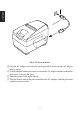
TABLE OF CONTENTS 1. Outline ............................................................................................................... 1 2. Unpacking and Installation ................................................................................2 2-1. Unpacking ..............................................................................................2 2-2. Locating the Printer ................................................................................3 2-3. Handling Care ...................
1. Outline ENGLISH The SP2000 Series Serial Impact Dot Matrix Printer is designed for use with electronic instruments such as POS, banking equipment, computer peripheral equipment, etc. The major features of the SP2000 series are as follows: 1. Bi-directional printing at approx. 3.1 lines/sec. 2. Serial interface or parallel interface. 3. The data buffer allows the unit to receive print data even during printing. 4. Peripheral unit drive circuit enables control of external devices such as cash drawers.
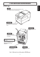
2-1. Unpacking After unpacking the unit, check that all the necessary accessories are included in the package. SP2300 type Printer Ribbon cartridge User’s manual SP2500 type Ferrite core Fasteners Printer Adaptor holder Cord holder Screws Spool (R series only) Note: The spool is only included with the R series (rewinder model). The spool is under the printer cover. Fig. 2-1 Unpacking If anything is missing, contact the dealer where you bought the printer and ask them to supply the missing part.
2-2. Locating the Printer ENGLISH When you locate your printer, keep the following tips in mind: 1. Protect your printer from excessive heat such as direct sunlight or heaters, and keep it away from moisture and dust. 2. Place the printer on a firm, level surface which is fairly vibration-free. 3. A steady power supply that is not subject to power surges should be connected to the printer.
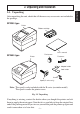
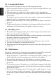
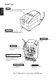
ENGLISH 3. Parts Identification and Nomenclature SP2300 type Cover Protects the printer from dust and reduces noise. Do not open the cover while printing. Control panel Features two control switches and two indicators to indicate printer status. Power switch Turns printer power on and off. AC adapter Refer to the following section for installation instructions. Peripheral unit drive circuit connector Connects to peripheral units such as cash drawers, etc. Do not connect this to a telephone.
SP2500 type ENGLISH Cover Protects the printer from dust and reduces noise. Do not open the cover while printing. Control panel Features two control switches and two indicators to indicate printer status. Power switch Turns printer power on and off. AC adapter Refer to the following section for installation instructions. Peripheral unit drive circuit connector Connects to peripheral units such as cash drawers, etc. Do not connect this to a telephone.
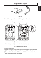
AC adaptor Power code Fig. 4-1 Use the following procedure to install the optional AC adapter. AC adapter Adapter holder Cord holder AC adapter cord [Before AC adaptor installed] Fasteners [After AC adaptor installed] Fig. 4-2 Flat side faces this way 1 Turn the printer over. 2 Plug the AC adapter’s cord into the socket as shown in the above illustration. Make sure the flat side of the plug is facing towards the inside of the printer.
ENGLISH Fig. 4-3 Fasten cord here 4 Coil the AC adapter cord into the space provided, and insert the AC adapter into its space. 5 Use the adapter holder and screw to secure the AC adapter and the cord holder and screw to secure the cord. 6 Turn the printer back right side up. 7 Plug the female end of the power cord into the AC adapter, and plug the other end into a power outlet.
The computer sends data to the printer through a cable to the printer’s interface (Serial Interface Connector Type: D-sub 25-pin or Parallel Interface Connector Type: 36-pin Centronics compatible). This printer does not come with a cable, so it is up to you to obtain one that suits your needs. Important! • The following instructions apply to the cable that is used with an IBMcompatible personal computer. Note that they do not apply to all types of computers and cables.
5 cm maximum 2 Pass the fastener through the ferrite core. ENGLISH Fastener Fig. 5-2 3 Loop the fastener around the cable and lock it. Use scissors to cut off any excess. Pull and cut Fig. 5-3 5-2. Connecting to Host Computer (Serial Interface) Ferrite core Screws Screwdriver Fig. 5-4 Connecting the serial interface cable 1 Turn off power to both the host computer and the printer.
Ferrite core 1 Turn off power to both the host computer and the printer. 2 Insert one terminal of the interface cable into the printer’s connector, as shown in the diagram, and fasten it there with the clasp. 3 Insert the other terminal of interface cable into the host computer’s connector, and again fasten it with the clasp. Fig.5-5 Connecting the parallel interface cable 5-4. Connecting to a Peripheral Unit You can connect a peripheral unit to the printer using a modular plug.
ENGLISH 1 Plug one end of the modular cable into the modular jack of the peripheral. 2 Remove the modular jack cover from the back of the printer and plug the other end of the modular cable into the jack of the printer. Fig. 5-8 Important! Do not connect a telephone line to the peripheral unit drive circuit connector; otherwise the printer and the telephone line may be damaged.
6-1. SP2300 Type 6-1-1. Loading the Ribbon Cartridge 1 Turn off power to the printer. 2 Lift the cover up approx. 3 cm. Hold the cover tilted at this angle, then pull it toward you to remove it. 3 Place the ribbon cartridge in the direction shown in Fig. 6-2 and press it down to load it. If loading of the ribbon cartridge is not satisfactory, press down the cartridge while rotating the ribbon feed knob in the direction of the arrow.
ENGLISH Note: When removing the ribbon cartridge, raise the A section and then remove it by holding the B section as shown in Fig. 6-3. A B Fig. 6-3 Removing the ribbon cartridge 6-1-2. Loading the paper Cover 1 Lift the cover up approx. 3cm. Hold the cover tilted at this angle, then pull it toward you to remove it. 2 Cut off the front edge of the roll paper perpendicularly. 3 Confirm that the power of the printer is turned on. Fig.
Fig. 6-5 Setting the paper 5 Insert the edge of the paper into the paper feeder. If inserted correctly, the edge of the paper will pass through the paper exit. 6 Insert the top edge of the paper into the tear bar slot, then mount the cover by reversing the procedure for removing the cover in step 1 above. Note: When the paper end mark appears on the paper, replace the roll paper before it runs out. Paper exit Tear bar Paper feeder Roll paper Fig. 6-6 Loading the paper – 14 – Fig.
6-2. SP2500 Type 6-2-1. Loading the Ribbon Cartridge ENGLISH Cover 1 Turn off power to the printer. 2 Lift the cover up approx. 3 cm. Hold the cover tilted at this angle, then pull it toward you to remove it. Power off Fig. 6-8 Removing the cover Auto cutter 3 Lift up the auto cutter and put it in a vertical position, as shown in Fig. 69. Fig.
Print head Ink ribbon Auto cutter Ribbon feed knob Notched part Ribbon cartridge Fig. 6-10 Loading the ribbon cartridge 4 Place the ribbon cartridge in the direction shown in Fig. 6-10 and press it down to load it. If loading of the ribbon cartridge is not satisfactory, press down the cartridge while rotating the ribbon feed knob in the direction of the arrow. 5 Turn the ribbon feed knob of the ribbon cartridge in the direction of the arrow to remove slack in the ribbon. 6 Close the Auto Cutter.
6-2-2. Loading the Paper Cover ENGLISH 1 Lift the cover up approx. 3 cm. Hold the cover tilted at this angle, then pull it toward you to remove it. Fig. 6-12 Removing the cover Roll paper 2 Cut off the front edge of the roll paper perpendicularly. 3 Confirm that the power of the printer is turned on. 4 While observing the direction of the roll, set the paper roll into the hollow as shown in Fig. 6-13. Fig.
5 Inset the edge of the paper into the paper feeder. If inserted correctly, the edge of the paper will pass through the auto cutter paper slit. The paper will be cut once. 6 Remove the cut tip, and mount the cover by reversing the procedure outlined in step 1. Note: When the paper end mark appears on the paper, replace the paper roll before it runs out. Auto cutter paper slit Paper feeder Roll paper Fig.
ENGLISH 7 Insert only the original (the upper paper) into the slit of the auto cutter. Insert the paper onto which you wish to copy (the lower paper) between the platen and the auto cutter. 8 Pull on the edge of the paper to remove any slack and then lower the auto cutter. 9 Insert the paper through the paper outlet and then replace the cover by reversing the removal steps. Note: When the paper end mark appears on the paper, replace the roll paper before it runs out. Paper outlet Auto cutter Fig.
When using the rewinder, follow steps 1 through 8 of section 6-2-2, and then continue with the procedure described below. 9 Feed approximately 20 cm of roll paper from the paper exit by pressing the [FEED] button. Upper paper FEED Lower paper Fig. 6-18 Loading the paper 0 Insert the end of the journal paper through the slit in the take-up spool as shown below. Be sure that the right side of the paper is against the reel. Spool Fig. 6-19 Spool – 20 – ENGLISH 6-2-3.
A Wind the paper onto the spool about three turns. ENGLISH Fig. 6-20 B While holding the paper down so that there is no slack, set the spool into place so the gear on the spool engages with the gear inside the printer. Reel Gear Frame Fig.
ENGLISH C Press the [FEED] button to wind the paper a round the take-up spool. Hold down the [FEED] button until there is no slack in the paper. FEED Fig. 6-22 D After installation is complete, replace the printer cover while passing the leading edge of the upper paper through the slit in the cover. Cover Lower paper Upper paper Fig.
6-3. Removing the Paper ENGLISH Remove the cover, then cut off the paper near the rear of the paper guide and press the FEED switch to feed out the paper remaining in the unit. When the paper runs out, the POWER lamp will blink. Note: 1. Remove the paper remaining in the printer by pressing the FEED switch. 2. When the paper end mark appears on the paper, replace the roll paper before it runs out. [When the rewinder is used] Remove the reel together with the paper rolled up on it. Paper Reel Spool Fig.
7-1. Basic Operation 4 ON LINE FEED POWER 1 2 3 Fig. 7-1 Control panel 1 ON LINE switch Switches the printer between ON LINE and OFF LINE. ON LINE and OFF LINE switching is possible only when paper is loaded in the printer. 2 FEED switch • When this switch is pressed and then released within 0.5 sec., the paper feeds on line. • When this switch is held depressed for more than 0.5 sec., the paper feeds continuously. (The above paper feed operation is possible for both ON LINE and OFF LINE modes.
7-2. Errors ENGLISH Determine the nature of the error by the flashing of the lamp or the sound of the buzzer. Error Description No paper Power lamp On-line lamp Buzzer Recovery Conditions Flashes at 1second intervals Off Paper near end of roll (when Near End Stop is operative) Flashes at 2second intervals Off On (after on-line switch pushed) None Mechanical error (other than cutter error) Flashes at 0.25second intervals Off One short (0.13 sec.) and one long (0.5 sec.
7-3. Switch Operation (Combined Switch Operation) FEED + POWER ON (Turn the power on while holding the FEED switch depressed.) Self-printing will be performed according to the VER. NO., DIP switch settings and character order. When the FEED switch is held continuously or when the FEED switch is depressed at the time of the end of self-printing, only the characters will be printed out repeatedly. Fig. 7-2 Self printing sample (when using serial interface printer) – 26 – ENGLISH 7-3-1.
7-3-2. Hexadecimal Dump Mode ENGLISH ON LINE + POWER ON (Turn the power on while holding the ON LINE switch depressed.) Each of the signals sent from the computer to the printer will be printed out in hexadecimal code. This function allows you to check if a control code sent to the printer by the program being used is correct or not. The last line is not printed if its data is less than one full line. However, if the ON LINE switch is pressed to set the off line mode, the last line will be printed.
• Use FEED to specify the block that appears to have the best aligned characters. Press FEED once to specify the first block, twice to specify the second block, and so on up to seven times to specify the seventh block. Warning beep will sound if you press FEED more than seven times. • After specifying a block, press ON LINE to register your selection and exit the Dot Alignment Adjust Mode. – 28 – ENGLISH This is caused when mechanical parts of the printer get out of alignment.
ENGLISH The dots alignment adjustment setting you selected is stored in printer memory and a pattern is printed using the selected setting followed by the message “Adjust Complete!” The printer ejects the paper after printing is complete. Note: You setting is not registered if you turn off printer power before pressing ON LINE to exit the Dot Alignment Adjust Mode. If a paper feed error occurs during this mode, the printer ejects the paper and this mode is cancelled.
The near-end sensor detects when the roll of paper loaded in it is reaching the end. The near-end sensor is normally disabled when the printer is shipped from the factory, but it can be enabled by your dealer using the memory switch. The information in this chapter applies only to printers whose near-end sensor is enabled. Important! Installation of the near-end sensor should normally be left to your dealer. 8-1.
ENGLISH 4 Determine the diameter of the roll paper you are using and find the required setting in the table below. Level 3 … Level 2 …… Level 1 ……… Distance A Setting Indicator Approximate 9 mm Approximate 7 mm Level 3 Level 2 ooo oo Approximate 5 mm Level 1 *1 o *1 Cannot be used with 2 and 3 ply. Fig. 8-2 A ø18 mm ø12 mm A Roll paper core Fig. 8-3 Note: 1.
1. Introduction ..................................................................................................... 33 2. Déballage et inspection ....................................................................................34 2-1. Déballage ............................................................................................. 34 2-2. Emplacement de l’imprimante ............................................................. 35 2-3. Précautions de manipulation ..................................
1. Introduction FRANÇAIS L’imprimante série à impact et matrice de points est conçue pour une utilisation avec des instruments électroniques tels que des terminaux points de vente, du matériel bancaire, du matériel périphérique pour ordinateurs, etc. Les caractéristiques principales des modèles de la série SP2000 sont les suivantes: 1. Impression bi-directionnelle à 3,1 lignes/sec. environ. 2. Interface série ou parallèle. 3.
2. Déballage et inspection 2-1. Déballage Après avoir déballé l’appareil, vérifiez si tous les accessoires nécessaires se trouvent dans la boîte. FRANÇAIS Modèle SP2300 Imprimante Cartouche à ruban Mode d’emploi Tore de ferrite Modèle SP2500 Imprimante Attache Plaque de fixation de l’adaptateur Plaque de fixation du cordon Vis Bobine (Série R uniquement) Remarque: La bobine est fournie uniquement avec les modèles de la série R (avec rembobineur). La bobine se trouve sous le capot de l’imprimante.
2-2. Emplacement de l’imprimante FRANÇAIS Pour installer correctement l’imprimante, gardez à l’esprit les conseils suivants: 1. Mettez l’imprimante à l’abri de températures excessivement élevées comme en plein soleil ou à proximité d’un appareil de chauffage, et à l’abri de l’humidité et de la poussière. 2. Installez l’imprimante sur une surface stable et de niveau sur laquelle l’imprimante ne sera pas soumise à des vibrations. 3. Veillez à ce que l’imprimante soit branchée sur une source secteur stable.
3. Identification des pièces et nomenclature Modèle SP2300 FRANÇAIS Capot Protège l’imprimante de la poussière et réduit le bruit. Ne pas ouvrir le capot pendant l’impression. Panneau de commande Comprend deux commutateurs de commande et trois témoins indiquant le statut de l’imprimante. Interrupteur d’alimentation Cet interrupteur vous permet de mettre l’imprimante sous tension et hors tension.
Modèle SP2500 Capot Protège l’imprimante de la poussière et réduit le bruit. Ne pas ouvrir le capot pendant l’impression. FRANÇAIS Panneau de commande Comprend deux commutateurs de commande et deux témoins indiquant le statut de l’imprimante. Interrupteur d’alimentation Cet interrupteur vous permet de mettre l’imprimante sous tension et hors tension.
4. Adaptateur secteur en option Adaptateur secteur FRANÇAIS Câble d’alimentation Fig. 4-1 Procéder de la manière suivante pour installer l’adaptateur secteur en option. Adaptateur secteur Plaque de fixation de l’adaptateur Cordon de l’adaptateur secteur Attache Plaque de fixation du cordon [Avant l’installation de l’adaptateur secteur] [Après l’installation de l’adaptateur secteur] Fig. 4-2 Vue côté plat 1 Retourner l’imprimante.
FRANÇAIS Fig. 4-3 Fixer le cordon ici 4 Enrouler le cordon de l’adaptateur secteur dans l’espace prévu et insérer l’adaptateur secteur dans son logement. 5 Utiliser la plaque de fixation de l’adaptateur et la visser pour caler l’adaptateur ; utiliser la plaque de fixation du cordon et la visser pour caler le cordon. 6 Retourner l’imprimante et la mettre à l’endroit.
L’ordinateur communique les données à l’imprimante via le câble connecté à l’interface de l’imprimante (type de connecteur d’interface série : D-Sub à 25 broches ou type de connecteur d’interface parallèle : compatible Centronics à 36 broches). Ce câble n’est pas fourni avec l’imprimante. Vous devrez donc vous en procurer un. Attention! • Les instructions suivantes concernent le câble de connexion employé sur un ordinateur personnel compatible IBM.
2 Passez l’attache dans le tore de ferrite. 5 cm maximum Attache FRANÇAIS Fig. 5-2 3 Passez l’attache autour du tore de ferrite et serrez-la. Coupez l’extrémité de l’attache à l’aide de ciseaux. Tirez et coupez Fig. 5-3 5-2. Raccordement à l’ordinateur hôte (interface série) Tore de ferrite Vis Toumevis 1 Mettez l’ordinateur hôte et l’imprimante hors tension. 2 Insérez un des connecteurs du câble d’interface dans la prise de l’imprimante et l’autre dans la prise de l’ordinateur hôte.
Tore de ferrite 1 Mettez l’ordinateur hôte et l’imprimante hors tension. 2 Insérez un des connecteurs du câble d’interface dans la prise de l’imprimante comme indiqué dans le schéma, et fixez-le avec les fermoirs 3 Insérez l’autre connecteur du câble d’interface dans la prise de l’ordinateur hôte, puis fixez-le également avec les fermoirs. Fig.5-5 Connexion du câble d’interface parallèle 5-4.
1 Raccordez une extrémité du câble modulaire à la prise modulaire du périphérique. 2 Retirez le cache de prise modulaire au dos de l’imprimante, et raccordez l’autre extrémité du câble modulaire dans la prise de l’imprimante. FRANÇAIS Fig. 5-8 Attention! Ne connectez pas une ligne de téléphone au connecteur de pilotage d’appareils périphériques, sous peine de risquer d’endommager l’imprimante et la ligne de téléphone.
6. Installation d’une cartouche à ruban et chargement du papier 6-1. Modèle SP2300 Capot Hors tension Fig. 6-1. Dépose du capot Séparateur de ruban Tête d’impression Ruban encreur 1 Mettez l’imprimante hors tension. 2 Soulevez le capot d’environ 3 cm. Tout en tenant le couvercle incliné à cet angle, tirez-le vers vous pour l’enlever. 3 Mettez la cartouche à ruban en place dans le sens indiqué dans la figure 6-2 et appuyez légèrement sur la cartouche afin qu’elle se mette en place.
Remarque: Pour enlever la cartouche à ruban, soulevez la partie A, puis enlevez la cartouche en la tenant par la partie B comme indiqué dans la figure 6-3. A FRANÇAIS B Fig. 6-3 Dégagement de la cartouche du ruban 6-1-2. Ehargement du papier Capot 1 Soulevez le capot d’environ 3 cm. Tout en tenant le couvercle incliné à cet angle, tirez-le vers vous pour l’enlever. 2 Coupez l’extrémité du papier perpendiculairement. 3 Vérifiez si l’imprimante est bien sous tension. Fig.
4 En faisant attention au sens du rouleau, mettez le rouleau de papier en place dans le creux, comme indiqué dans la figure 6-5. FRANÇAIS Rouleau de papier Fig. 6-5 Chargement du papier Mécanisme d’avance de papier Fente de sortie de papier 5 Insérer le bord du papier dans le mécanisme d’avance de papier. S’il est inséré correctement, le bord du papier ressortira par la fente de sortie de papier.
6-2. Modèle SP2500 6-2-1. Installation d’une cartouche à ruban Capot FRANÇAIS Hors tension 1 Mettez l’imprimante hors tension. 2 Soulevez le capot d’environ 3 cm. Tout en tenant le couvercle incliné à cet angle, tirez-le vers vous pour l’enlever. Fig. 6-8 Dépose du capot Unité de découpage automatique 3 Soulevez l’unité de découpage automatique pour la mettre en position verticale, comme indiqué dans la figure 6-9. Fig.
4 Mettez la cartouche à ruban en place dans le sens indiqué dans la figure Téte d’impression 6-10 et appuyez légèrement sur la Ruban encreur cartouche afin qu’elle se mette en Unité de découplace. Si la mise en place de la page automatique Bouton cartouche n’est pas satisfaisante, apd’alimentation du ruban puyez sur la cartouche tout en faiParties avec sant tourner le bouton d’alimentaencoches tion du ruban de la cartouche dans le sens de la flèche.
6-2-2. Chargement du papier Capot 1 Soulevez le capot d’environ 3 cm. Tout en tenant le couvercle incliné à cet angle, tirez-le vers vous pour l’enlever. FRANÇAIS Fig. 6-12 Dépose du capot Rouleau de papier 2 Coupez l’extrémité du papier perpendiculairement. 3 Vérifiez si l’imprimante est bien sous tension. 4 En faisant attention au sens du rouleau, mettez le rouleau de papier en place dans le creux, comme indiqué dans la figure 6-13. Fig.
Mécanisme d’avance de papier Fente de sortie de papier Rouleau de papier Fig. 6-14 Chargement du papier 5 Insérez l’extrémité du papier dans le mécanisme d’avance de papier. S’il est inséré correctement, le bord du papier passera par la fente de l’unité de découpage automatique. Le papier sera coupé une fois. 6 Enlevez le bout coupé et remettez le capot en place en suivant la procédure inverse de celle décrite à l’étape 1.
FRANÇAIS Sortie de papier Unité de découpage automatique 7 Insérez seulement l’original (feuille supérieure) dans la fente de l’unité de découpage automatique. Insérez le papier sur lequel vous souhaitez effectuer la copie (feuille inférieure) entre le cylindre et l’unité de découpage automatique. 8 Tirez sur l’extrémité du papier afin de tendre le papier, puis rabaissez l’unité de découpage automatique.
6-2-3. Rembobineur Feuille supérieure FEED Feuille inférieure Fig. 6-18 Chargement du papier 0 Insérez l’extrémité du papier dans la fente de la bobine réceptrice et le rouleau de la façon indiquée ci-dessous. Faites attention à ce que le bord droit du papier soit bien contre le bord de la collerette. Bobine Fig. 6-19 Bobine – 52 – FRANÇAIS Pour utiliser le rembobineur, procédez aux étapes 1 à 8 de la section 6-2-2, puis poursuivez comme suit.
A Enrouler le papier sur la bobine sur environ trois tours. FRANÇAIS Fig. 6-20 B Tenir le papier de sorte qu’il reste tendu et mettre la bobine en place de manière que le mécanisme de la bobine s’emboîte dans le mécanisme de l’imprimante. Collerette Mécanisme Cadre Fig.
C Appuyez sur la touche [FEED] pour rembobiner le papier sur la bobine réceptrice. Maintenez la touche [FEED] enfoncée jusqu’à ce le papier soit tendu. FRANÇAIS FEED Fig. 6-22 D Lorsque le rouleau est en place, remettre le couvercle de l’imprimante en faisant passer le bord de l’amorce de la feuille supérieure dans la fente du couvercle. Capot Feuille inférieure Feuille supérieure Fig.
6-3. Enlèvement d’un rouleau de papier Retirez le capot, puis coupez le papier juste derrière le guide de papier et appuyez sur la touche d’avance FEED afin de faire sortir le reste du papier qui se trouve toujours dans l’imprimante. Quand tout le papier est sorti, le témoin POWER clignote. FRANÇAIS Remarques: 1. Enfoncez la touche d’avance FEED pour retirer le reste du papier qui se trouve dans l’imprimante. 2. N’attendez pas que le rouleau de papier soit épuisé avant de le remplacer.
7. Panneau de commande 4 ON LINE FEED POWER 1 2 3 Fig. 7-1 Panneau de commande 1 Touche ON LINE Cette touche permet de mettre l’imprimante en ligne ou hors ligne. Vous ne pouvez effectuer cette commutation que si du papier est chargé dans l’imprimante. 2 Touche d’avance FEED • Si vous appuyez sur cette touche, puis la relâchez moins de 0,5 seconde après, le papier avancera d’une ligne à la fois.
7-2. Erreurs Déterminez la nature de l’erreur en fonction du clignotement du témoin ou du son de la sonnerie.
7-3. Utilisation des touches (Utilisation combinée des touches) FEED + POWER ON (Mettez l’imprimante sous tension tout en maintenant la touche FEED enfoncée.) Le test d’impression sera effectué conformément au réglage du numéro de vérification, des commutateurs DIP et de l’ordre des caractères. Si vous maintenez la pression sur la touche FEED ou si vous appuyez sur la touche FEED à la fin du test d’impression, seuls les caractères seront imprimés à plusieurs reprises. Fig.
7-3-2. Vidage hexadécimal FRANÇAIS ON LINE + POWER ON (Mettez l’imprimante sous tension tout en maintenant la touche ON LINE enfoncée.) Chacun des signaux envoyés de l’ordinateur à l’imprimante sera imprimé en code hexadécimal. Cette fonction vous permet de vérifier si un code de contrôle envoyé à l’imprimante par le programme utilisé est correct ou non. La dernière ligne n’est pas imprimée si les données correspondantes ne remplissent pas une ligne complète.
• Utilisez la touche FEED pour spécifier le bloc dont l’alignement des caractères semble optimal. Appuyez une fois sur FEED pour spécifier le premier bloc, deux fois pour spécifier le deuxième bloc, et ainsi de suite jusqu’à sept fois pour spécifier le septième bloc. Un avertisseur sonore fait entendre si vous appuyez plus de sept fois sur la touche FEED. • Après avoir spécifié un bloc, appuyez sur ON LINE pour sauvegarder votre sélection et quitter le mode de réglage d’alignement des points.
Le réglage d’alignement des points que vous avez sélectionné est sauvegardé dans la mémoire, et l’imprimante imprime une série de lignes graduées correspondant à l’état d’impression sélectionné, suivie du message “Adjust Completed!”, vous indiquant que le réglage est terminé. L’imprimante éjecte ensuite le morceau de papier fort.
Le capteur détecte lorsque le rouleau chargé arrive presque à la fin du papier. Ce capteur est normalement désactivé à la sortie d’usine mais on peut l’activer à l’aide de l’interrupteur de mémoire (ou s’adresses à son revendeur). Les informations contenues dans le présent chapitre concernent uniquement les imprimantes dont le capteur de détection de fin de papier est activé. Attention! L’installation du capteur de fin de papier doit normalement être effectuée par le revendeur. 8-1.
4 Définir le diamètre du rouleau de papier utilisé et situer le réglage correspondant dans le tableau cidessous. Distance A Environ 9 mm FRANÇAIS Niveau 3 … Niveau 2 …… Niveau 1 ……… Réglage Niveau 3 Indicateur ooo Environ 7 mm Niveau 2 oo Environ 5 mm Niveau 1 *1 o *1 Ne pas utiliser avec des papiers à 2 ou 3 exemplaires. Fig. 8-2 A ø18 mm ø12 mm Mandrin du rouleau de papier Fig. 8-3 A Remarque: 1.
1. Kurzbeschreibung ............................................................................................65 2. Auspacken und Aufstellen ............................................................................... 66 2-1. Überprüfen ........................................................................................... 66 2-2. Wahl eines Aufstellungsorts für den Drucker ......................................67 2-3. Hinweise zum Umgang ............................................................
1. Kurzbeschreibung Der serielle Nadeldrucker der Serie SP2000 ist zur Verwendung mit elektronischen Instrumenten wie POS, Bankgeräte, Computerzubehör, etc. gedacht. Die wichtigsten Merkmale der Serie SP2000 sind: 1. Bidirektioneller Druck mit ca. 3,1 Zeilen/s 2. Serielle oder parallele Schnittstelle 3. Pufferspeicher erlaubt, Druckdaten auch während des Druckvorgangs zu empfangen. 4.
2. Auspacken und Aufstellen 2-1. Überprüfen Sie den Kartoninhalt, und vergewissern Sie sich, daß alle unten abgebildeten Teile vorhanden sind. Typ SP2300 Drucker DEUTSCH Farbbandkassette Bedienungsanleitung Typ SP2500 Ferritkern Drucker Befestigungsband Adapterhalter Kabelhalter Schrauben Bobine (Nur Modelle der R-Serie) Hinweis: Die Bobine gehört nur zum Lieferumfang der Modelle der R-Serie (mit Rückspulvorrichtung) und befindet sich unterhalb der Drucker-Abdekkung. Abb.
2-2. Wahl eines Aufstellungsorts für den Drucker DEUTSCH Bevor Sie den Drucker auspacken, sollten Sie einige Minuten damit verbringen, einen geeigneten Aufstellungsort auszusuchen. Denken Sie dabei an die folgenden Punkte: 1. Den Drucker vor Hitzequellen wie direktem Sonnenlicht oder Heizkörpern schützen und von Feuchtigkeit und Staub fernhalten. 2. Den Drucker auf einem flachen, aber festen Untergrund aufstellen, wo keine Vibrationen vorhanden sind. 3.
3. Beschreibung und Bezeichnung der Geräteteile Typ SP2300 DEUTSCH Abdeckung Schüzt den Drucker vor Staub, und reduziert das Betriebsgeräsch. Nicht die Frontabdeckung würend des Druckens öfnen. Bedienfeld Hat zwei Bedienungstasten und zwei Anzeigen zur Anzeige des Druckerzustands. Netzschalter Zum Ein-und Ausschalten des Druckers. Netzadapter Anweisungen für die Installation finden sich im nachstehenden Abschnitt. PeripheriegerätSteueranschluß Zum Anschluß an Peripheriegeräte wie Registrierkassen etc.
Typ SP2500 Abdeckung Schützt den Drucker vor Staub, und reduziert das Betriebsgeräusch. Nicht die Frontabdeckung während des Druckens öffnen. DEUTSCH Bedienfeld Hat zwei Bedienungstasten und zwei Anzeigen zur Anzeige des Druckerzustands. Netzschalter Zum Ein-und Ausschalten des Druckers. Netzadapter Anweisungen für die Installation finden sich im nachstehenden Abschnitt. PeripheriegerätSteueranschluß Zum Anschluß an Peripheriegeräte wie Registrierkassen etc.
4. Als Sonderzubehör erhältlicher Netzadapter Netzadapter Netzkabel Den als Sonderzubehör erhältlichen Netzadapter auf folgende Weise installieren. Netzadapter Adapter holder Kabelhalter Netzadapterkabel [Vor Installation des Netzadapters] Befestigungsband [Nach Installation des Netzadapters] Abb. 4-2 Ansicht der flachen Seite 1 Den Drucker umlegen. 2 Das Kabel des Netzadapters, wie in der nachstehenden Abbildung dargestellt, in die Buchse einstecken.
DEUTSCH Abb. 4-3 Kabel hier befestigen 4 Das Kabel des Netzadapters in den dafür vorgesehenen Raum gewickelt einlegen und den Netzadapter in den dafür vorgesehenen Raum einlegen. 5 Den Netzadapter mit dem Adapterhalter und der Schraube und das Kabel mit dem Kabelhalter und der Schraube sichern. 6 Den Drucker wieder in Normalstellung aufrichten. 7 Die Buchsensteckverbindung des Netzkabels in den Netzadapter und die andere Seite in die Wandsteckdose einstecken.
5. Anschließen Wichtig! • Die folgende Anleitung bezieht sich auf das von IBM-kompatiblen PCs benutzte Kabel und ist deshalb nicht auf alle Computer und Kabel zutreffend. Wenden Sie sich bitte an Ihren Fachhändler, falls Sie Fragen hinsichtlich des für Ihren Computer geeigneten Kabeltyps haben. • Vor dem Anschließen der Kabel sicherstellen, daß der Drucker ausgeschaltet und vom Netz getrennt ist. 5-1.
2 Führen Sie den Kabelbinder durch den Ferritkern. Maximum 5 cm Kabelbinder Abb. 5-2 DEUTSCH Ziehen und abschneiden 3 Führen Sie den Kabelbinder um das Kabel und sperren Sie ihn. Schneiden Sie überschüssiges Band mit einer Schere ab. Abb. 5-3 5-2. Anschließen an den Hostcomputer (serielle Schnittstelle) Ferritkern Schrauben Schraubenzieher Abb. 5-4 Anschließen des Schnittstellenkabels 1 Schalten Sie sowohl den Hostcomputer als auch den Drucker aus.
Ferritkern Abb.5-5 Anschließen des parallelen Schnittstellenkabels 1 Schalten Sie sowohl den Hostcomputer als auch den Drucker aus. 2 Stecken Sie einen Stecker des Schnittstellenkabels in die parallele Schnittstellenbuchse am Drucker, und klemmen Sie ihn mit den Haltebügeln fest. 3 Stecken Sie den anderen Stecker des Schnittstellenkabels in die parallele Schnittstellenbuchse am Hostcomputer, und klemmen Sie ihn mit den Haltebügeln fest. 5-4.
1 Einen Stecker des Modularkabels in die Modularbuchse am Peripheriegerät stecken. 2 Die Modularbuchsenabdeckung von der Rückseite des Druckers abnehmen, und den anderen Stecker des Modularkabels in die Modularbuchse am Drucker stecken. DEUTSCH Abb. 5-8 Wichtig! Keine Telefonleitung an den Peripheriegerät-Steueranschluß anschließen. Wenn dies geschieht, besteht die Gefahr von Schäden am Drucker und an der Telefonleitung.
6. Einlegen von Farbbandkassette und Papier 6-1. Typ SP2300 Frontabdeckung Netzschalter aus Abb. 6-1 Abdeckung abnehmen Abstandhalter für Farbband Druckkopf 1 Den Netzschalter am Drucker in Aus-Stellung stellen. 2 Zum Abnehmen der Frontabdeckung diese ca. 3 cm anheben, und nach vorne ziehen. 3 Die Farbbandkassette in der Richtung einsetzen wie in der Abbildung 6-2 gezeigt und eindrücken, bis sie hörbar einrastet.
Hinweis: Beim Entfernen der Farbbandkassette den Teil A anheben und dann die Kassette an Teil B halten und Abziehen wie in Abbildung 6-3 gezeigt. A DEUTSCH B Abb. 6-3 Farbbandkassette ausbauen 6-1-2. Einlegen von Papier Abdeckung 1 Die Abdeckung um etwa 3 cm anheben. Die Abdeckung in diesem Winkel halten, und dann zum Entfernen nach vorne ziehen. 2 Schneiden Sie die Vorderkante des Rollenpapiers in einer geraden Linie ab. 3 Bestätigen Sie, daß der Drucker eingeschaltet ist. Abb.
Abb. 6-5 Einlegen von Papier Uscita della carta Alimentatore della carta 5 Die Kante des Papiers in den Papiereinzug setzen. Wenn richtig eingesetzt, läuft die Kante des Papiers durch den Papieraus lauf. 6 Führen Sie die Oberkante des Papiers in den Abreißkantenschlitz ein, und bringen dann die Abdeckung an, indem Sie die Ausbauschritte von Schritt 1 oben in umgekehrter Reihenfolge ausführen.
6-2. Typ SP2500 6-2-1. Einlegen der Farbbandkassette 1 Stellen Sie den Netzschalter am Drucker in Aus-Stellung. 2 Zum Abnehmen der Frontabdeckung heben Sie diese ca. 3 cm an, und ziehen sie dann nach vorne. Frontabdeckung Netzschalter aus DEUTSCH Abb. 6-8 Abdeckung abnehmen 3 Heben Sie das Schneidwerk an und stellen es in senkrechte Stellung, wie in Abbildung 6-9 gezeigt. Schneidwerk Abb.
4 Die Farbbandkassette in der Richtung einsetzen wie in der Abbildung Druckkopf 6-10 gezeigt und eindrücken, bis sie Farbband hörbar einrastet. Wenn die Farbbandkassette nicht richtig sitzt, Schneidwerk eingedrückt halten und gleichzeitig Farbbandden Farbbandknopf in Pfeilrichtung knopf drehen. Kerbteil 5 Um Schlaufen im Farbband aufzuwickeln, den Farbbandzuführknopf der Farbbandkassette in Pfeilrichtung drehen. 6 Das Schneidwerk schließen.
6-2-2. Einlegen von Papier Abdeckung 1 Die Abdeckung um etwa 3 cm anheben. Die Abdeckung in diesem Winkel halten, und dann zum Entfernen nach vorne ziehen. DEUTSCH Abb. 6-12 Entfernen der Abdeckung Rollenpapier 2 Schneiden Sie die Vorderkante des Rollenpapiers in einer geraden Linie ab. 3 Bestätigen Sie, daß der Drucker eingeschaltet ist. 4 Unter Beachtung der Richtung des Rollenpapiers das Rollenpapier in die Vertiefung setzen, wie in Abbildung 6-13 gezeigt. Abb.
Uscita della carta Alimentatore della carta Rollenpapier 5 Die Papierkante in den Papiereinzug setzen. Wenn richtig eingesetzt, läuft die Papierkante durch den Schlitz des automatischen Papierabschneiders. Das Papier wird einmal abgeschnitten. 6 Die abgeschnittene Spitze entfernen, und den Deckel in umgekehrter Reihenfolge wie in Schritt 1 beschrieben wieder anbringen. Hinweis: Wenn die PapierendeMarkierung auf dem Papier erscheint, das Rollenpapier ersetzen, bevor es verbraucht ist. Abb.
Papierauslaß DEUTSCH Schneidwerk Abb. 6-16 Papierauslaß an der Frontabdeckung 7 Nur das Original (obere Papier) in den Schlitz des automatischen Abschneiders setzen. Das Papier auf dem kopiert werden soll (das untere Papier) zwischen Druckwalze und automatischen Abschneider setzen. 8 Ziehen Sie die Kante des Papierstau, um Schlaufen zu beseitigen, und senken Sie dann das Schneidwerk ab.
6-2-3. Rückspulvorrichtung Zur Betätigung der Rückspulvorrichtung die Schritte 1 bis 8 ausführen und dann wie folgt weiterfahren. 9 Die Papiervorschubtaste FEED drücken, bis der Anfang der Papierrolle etwa 20 cm aus dem Papierauslauf ausläuft. Obere Papierlage Untere Papierlage Abb. 6-18. Papier einlegen 0 Das Ende der Journalstreifenrolle, wie unten gezeigt, in den Schlitz der Aufwickelspule einführen. Hierbei darauf achten, daß die richtige Papierseite zum Spulenflansch weist. Spule Abb.
A Das Papier etwa drei Umdrehungen um die Spule wickeln. DEUTSCH Abb. 6-20 B Das Papier nach unten halten, damit es sich nicht lockern kann. Dabei gleichzeitig die Spule in Stellung bringen, so daß das Zahnrad auf der Spule und das Zahnrad im Inneren des Druckers ineinandergreifen. Spulenflansch Zahnrad Rahmen Abb.
C Die Papiervorschubtaste [FEED] zum Aufwickeln des Papiers durch die Aufwickelspule drücken. Die Papiervorschubtaste [FEED] gedrückt halten, bis das Papier straff gewickelt ist. DEUTSCH FEED Abb. 6-22 D Wenn alles so eingerichtet ist wie Sie es wünschen, die Abdeckung des Druckers wieder anbringen. Dabei gleichzeitig die Vorderkante der oberen Papierlage durch den Schlitz in der Abdeckung führen. Abdeckung Untere Papierlage Obere Papierlage Abb.
6-3. Entfernen des Rollenpapiers Nehmen Sie die Abdeckung ab, und schneiden Sie das Papier in der Nähe der Papierführung ab. Dann drücken Sie die FEED-Taste, um den Rest des Papiers auszugeben, der noch in der Einheit ist. Wenn das Papier verbraucht ist, blinkt das Lämpchen POWER. Hinweis:1. Durch Drücken der FEED-Taste wird der Rest des noch im Drucker befindlichen Papiers ausgegeben. 2.
7. Bedienfeld 4 ON LINE FEED POWER 1 2 3 Abb. 7-1 Bedienfeld 1 Taste ON LINE Schaltet den Drucker zwischen Online und Off-line Betrieb um. Umschalten ist nur möglich, wenn Papier im Drucker eingelegt ist. 2 FEED-Taste • Wenn diese Taste gedrückt und dann innerhalb von 0,5 s losgelassen wird, wird das Papier um eine Zeile vorgeschoben. • Wenn diese Taste länger als 0,5 s gedrückt gehalten wird, wird das Papier kontinuierlich vorgeschoben.
7-2. Fehler Die Art des Fehlers anhand der blinkenden Lampe oder des Signaltons bestimmen.
7-3. Tastenbedienung (kombinierte Tastenbedienung) 7-3-1. Selbstdruck DEUTSCH FEED + POWER ON (Gerät einschalten, während die Taste FEED gedrückt gehalten wird.) Der Selbstdruck wird entsprechend der VER.NO. DIP-Schaltereinstellung und der Zeichenfolge ausgeführt. Wenn die Taste FEED kontinuierlich gedrückt gehalten wird oder wenn FEED am Ende des Selbstdrucks gedrückt wird, werden nur die Zeichen wiederholt ausgedruckt. Abb.
7-3-2. Sedezimale Datenausgabe DEUTSCH ON LINE + POWER ON (Gerät einschalten, während die Taste ONLINE gedrückt gehalten wird.) Bei diesem Befehle werden alle Codes (Zeichencodes und Steuercodes), die vom Computer zum Drucker gesandt werden, in sedezimaler Form ausgedruckt. Der sedezimale Datenausdruck ist nützlich, um zu prüfen, ob vom Drucker ausgegebene Steuercodes richtig sind. Die letzte Zeile wird nicht ausgedruckt, wenn sie nicht vollständig mit Daten gefüllt ist.
• Die Taste FEED drücken, um den Block zu wählen, der die am besten ausgerichteten Zeichen hat. Die Taste einmal drücken, um den ersten Block zu wählen, zweimal für den zweiten Block, und so weiter bis zum siebten Block. Wenn die Taste mehr als sieben Mal gedrückt wird, ertönt ein Warnton. • Nach dem Wählen eines Blocks die Taste ON LINE drücken, um die Wahl einzugeben, und den Punkteinstellmodus zu verlassen.
Die Einstellungen für die Punktausrichtung werden im Druckerspeicher gespeichert, und ein Muster wird mit der gewählten Einstellung ausgedruckt, gefolgt von der Meldung “Adjust Complete!”. Der Drucker gibt das Papier nach dem Druckvorgang aus. DEUTSCH Hinweis: Wenn der Drucker ausgeschaltet wird, ohne die Taste ON LINE zum Verlassen des Punkteinstellmodus zu drücken, werden die Einstellungen nicht gespeichert.
8. Als Sonderzubehör erhältlicher Papierende-Sensor Der Papierende-Sensor stellt fest, wenn sich die eingelegte Papierrolle dem Ende nähert. Der Papierende-Sensor ist normalerweise bei Versand des Druckers ab Werk ausgeschaltet, er kann aber mit dem Speicherschalter eingeschaltet werden (ggf. Sich an den Fachhändler wenten). Die Angaben in diesem Kapitel beziehen sich nur auf Drucker, deren Papierende-Sensor eingeschaltet ist. 8-1.
4 Den Durchmesser der von Ihnen verwendeten Papierrolle ermitteln und die erforderliche Einstellung in der nachstehenden Tabelle ablesen. Abstand A Etwa 9 mm Stufe 3 … Stufe 2 …… Stufe 1 ……… Einstellung Stufe 3 Anzeige ooo Etwa 7 mm Stufe 2 oo Etwa 5 mm Stufe 1 *1 o *1 Für 2 und 3 Lagen ungeeignet. Abb. 8-2 DEUTSCH A ø18 mm ø12 mm Kern der Papierrolle Abb. 8-3 A Hinweis: 1.
1. Descrizione ......................................................................................................97 2. Disimballaggio e installazione ........................................................................ 98 2-1. Disimballaggio .....................................................................................98 2-2. Collocazione della stampante .............................................................. 99 2-3. Precauzioni per l’uso................................................
1. Descrizione La stampante seriale a matrice di impunti a impatto SP2000 è stata progettata per l’uso con strumenti elettronici come POS, apparecchiature bancarie, periferiche computer, ecc. Le principali caratteristiche della serie SP2000 sono come segue: 1. Stampa bidirezionale a circa 3,1 righe/sec. 2. Interfaccia seriale o interfaccia parallelo 3. Buffer dati per la ricezione di dati di stampa anche durante la stampa 4.
2. Disimballaggio e installazione 2-1. Disimballaggio Dopo aver disimballato l’unità, controllare che tutti gli accessori necessari siano inclusi nella confezione. Tipo SP2300 Stampante Manuale di istruzioni Anello di ferrite Tipo SP2500 Fascetta di fissaggio Stampante Supporto adattatore Supporto cavo Viti Spola (Solo serie R) Nota: La spola è inclusa solo con la serie R (modelli con riavvolgitore). La spola si trova sotto il coperchio stampante. Fig.
2-2. Collocazione della stampante Quando si colloca la stampante, tenere presenti le seguenti considerazioni: 1. Proteggere la stampante da calore eccessivo come luce solare diretta o caloriferi e tenerla lontana da umidità e polvere. 2. Collocare la stampante su una superficie stabile e piana che non sia soggetta a vibrazioni. 3. Collegare alla stampante una fonte di alimentazione stabile che non sia soggetta a picchi.
3. Identificazione delle parti e nomenclatura Tipo SP2300 ITALIANO Coperchio Protegge la stampante dalla polvere e riduce il rumore. Non aprire il coperchio durante la stampa. Pannello comandi Dispone di due interruttori di controllo e due indicatori dello stato della stampante. Interruttore di alimentazione Per accendere e spegnere la stampante. Adattatore CA Fare riferimento alla seguente sezione per le istruzioni d’installazione.
Tipo SP2500 Coperchio Protegge la stampante dalla polvere e riduce il rumore. Non aprire il coperchio durante la stampa. ITALIANO Pannello comandi Dispone di due interruttori di controllo e due indicatori dello stato della stampante. Interruttore di alimentazione Per accendere e spegnere la stampante. Adattatore CA Fare riferimento alla seguente sezione per le istruzioni d’installazione. Connettore circuito pilota per unità periferiche Per il collegamento a unità periferiche come registri di cassa, ecc.
4. Adattatore CA opzionale Adattatore CA Cavo di alimertazione Fig. 4-1 Utilizzare la seguente procedura per installare l’adattatore CA opzionale Supporto adattatore Fascetta di fissaggio ITALIANO Adattatore CA Supporto cavo Cavo adattatore CA [Prima dell’installazione dell’adattatore CA] [Dopo l’installazione dell’adattatore CA] Fig. 4-2 La parte piana è rivolta in questa direzione 1 Capovolgere la stampante. 2 Inserire il cavo dell’adattatore CA nella presa come mostrato nella figura sotto.
ITALIANO Fig. 4-3 Fissare il cavo in questo punto 4 Avvolgere il cavo dell’adattatore CA nello spazio previsto, quindi inserire l’adattatore CA nel suo alloggiamento. 5 Utilizzare il supporto dell’adattatore avvitandolo per fissare l’adattatore CA, quindi utilizzare il supporto del cavo avvitandolo per fissare il cavo. 6 Rimettere la stampante in posizione dritta. 7 Inserire l’estremità femmina del cavo di alimentazione nell’adattatore CA, quindi inserire l’altra estremità in una presa di corrente.
5. Connessione Il computer invia dati alla stampante tramite un cavo collegato all’interfaccia della stampante (tipo connettore interfaccia seriale: D-sub a 25 terminali o tipo connettore interfaccia parallela: compatibile Centronics a 36 terminali). Questa stampante non è dotata di cavo, che deve essere acquistato a seconda delle esigenze di impiego. 5-1. Installazione dell’anello di ferrite 1 Fissare l’anello di ferrite al cavo come mostrato nell’illustrazione qui sotto. Anello di ferrite Cavo Fig.
2 Far passare la fascetta di fissaggio attraverso l’anello di ferrite. 5 cm massimo Fascetta di fissaggio Fig. 5-2 Tirare e tagliare 3 Avvolgere la fascetta intorno al cavo e fissarla. Usare delle forbici per tagliare la parte in eccesso. ITALIANO Fig. 5-3 5-2. Collegamento al computer ospite (interfaccia seriale) Anello di ferrite Viti Cacciavite 1 Spegnere sia il computer ospite che la stampante.
5-3. Collegamento al computer ospite (interfaccia parallela) Anello di ferrite 1 Spegnere sia il computer ospite che la stampante. 2 Inserire un terminale del cavo interfaccia nel connettore sulla stampante, come mostrato nella figura, e fissarlo con il morsetto. 3 Inserire l’altro terminale del cavo interfaccia nel connettore sul computer ospite e fissare anche questo con il morsetto. Fig.
1 Collegare un capo del cavo modulare alla presa modulare della periferica. 2 Rimuovere il coperchio presa modulare dal retro della stampante e collegare l’altro capo del cavo modulare alla presa sulla stampante. Fig. 5-8 ITALIANO Importante! Non collegare una linea telefonica al connettore circuito pilota per unità periferiche. Altrimenti si potrebbero avere danni alla stampante ed alla linea telefonica.
6. Inserimento della cartuccia nastro e della carta 6-1. Tipo SP2300 Coperchio Spegnere Fig. 6-1 Rimozione del coperchio Separatore del nastro Testina di stampa 1 Spegnere la stampante. 2 Sollevare il coperchio di 3 cm circa. Tenere il coperchio inclinato a questa angolazione e tirarlo verso di sè per rimuoverlo. 3 Inserire la cartuccia nastro nella direzione mostrata nella Fig. 6-2 e premerla in basso per caricarla.
Nota: Quando si rimuove la cartuccia nastro, sollevare la parte A e quindi rimuovere la cartuccia tenendo la parte B come mostrato nella Fig. 6-3. A B Fig. 6-3 Rimuovere la cartuccia del nastro ITALIANO 6-1-2. Inserimento della carta Coperchio 1 Sollevare il coperchio di 3 cm circa. Tenere il coperchio inclinato a questa angolazione e tirarlo verso di sè per rimuoverlo. 2 Tagliare perpendicolarmente l’estremità iniziale della carta del rotolo. 3 Verificare che la stampante sia accesa. Fig.
Fig. 6-5 Inserimento della carta Uscita della carta Alimentatore della carta 5 Inserire il bordo della carta nell’alimentatore della carta. Se è inserito correttamente, il bordo della carta passa attraverso l’uscita della carta. 6 Inserire l’estremità superiore della carta nella fessura della barra di strappo e quindi montare il coperchio con il procedimento inverso di quello usato per rimuovere il coperchio al punto 1 sopra.
6-2. Tipo SP2500 6-2-1. Inserimento della cartuccia nastro Coperchio Spegnere 1 Spegnere la stampante. 2 Sollevare il coperchio di 3 cm circa. Tenere il coperchio inclinato a questa angolazione e tirarlo verso di sè per rimuoverlo. ITALIANO Fig. 6-8 Rimozione del coperchio Taglierina automatica 3 Sollevare la taglierina automatica e collocarla in posizione verticale, come mostrato nella Fig. 6-9. Fig.
Testina di stampa Manopola di avanzamento nastro Nastro inchiostrato Taglierina automatica Parte incassata Cartuccia nastro Fig. 6-10 Inserimento della cartuccia nastro 4 Inserire la cartuccia nastro nella direzione mostrata nella Fig. 6-10 e premerla in basso per caricarla. Se il caricamento della cartuccia nastro non è soddisfacente, premere in basso la cartuccia nastro girando la manopola di avanzamento nastro in direzione della freccia.
6-2-2. Inserimento della carta Coperchio 1 Sollevare il coperchio di 3 cm circa. Tenere il coperchio inclinato a questa angolazione e tirarlo verso di sè per rimuoverlo. Fig. 6-12 Rimozione del coperchio ITALIANO Rotolo di carta 2 Tagliare perpendicolarmente l’estremità iniziale della carta del rotolo. 3 Verificare che la stampante sia accesa. 4 Osservando l’orientamento del rotolo, collocare il rotolo di carta nel vano come mostrato in Fig.6-13. Fig.
[Quando si usa carta semplice] 5 Inserire il bordo della carta nell’alimentatore carta. Se è inserito correttamente, il bordo della carta passa attraverso la fessura carta della taglierina automatica. La carta viene tagliata una volta. 6 Rimuovere l’estremità tagliata e montare il coperchio seguendo in ordine inverso il procedimento descritto al punto 1. Nota: Quando il segno di fine carta appare sulla carta, sostituire il rotolo prima che finisca.
7 Inserire solo la carta dell’originale (foglio superiore) nella fessura della taglierina automatica. Inserire la carta di copia (foglio inferiore) tra il rullo e la taglierina automatica. 8 Tirare il bordo del carta per eliminare eventuali allentamenti e quindi abbassare la taglierina automatica. 9 Inserire la carta attraverso l’apertura carta e quindi rimettere il coperchio seguendo in ordine inverso il procedimento di rimozione.
6-2-3. Riavvolgitore Quando si usa il riavvolgitore, eseguire i punti da 1 a 8 della sezione 6-2-2 e quindi procedere come segue. 9 Fare avanzare la carta del rullo di circa 20 cm dall'uscita carta premendo l'interruttore FEED. Carta superiore FEED ITALIANO Carta inferiore Fig. 6-18 Caricamento della carta 0 Inserire il capo della carta copia tra la spola di avvolgimento e la bobina come mostrato sotto. Assicurarsi che il lato destro della carta sia contro la flangia della bobina. Spola Fig.
A Arrotolare la carta sulla spola facendo tre giri. Fig. 6-20 ITALIANO B Trattenendo la carta per evitare che si allenti, fissare la spola in modo che l'ingranaggio su quest'ultima si innesti sull'ingranaggio all'interno della stampante. Flangia Ingranaggio Telaio Fig.
C Premere il tasto [FEED] e avvolgere la carta sulla bobina di avvolgimento. Tenere premuto il tasto [FEED] fino a che non rimane allentamento nella carta. ITALIANO FEED Fig. 6-22 D Dopo avere sistemato ogni cosa, rimettere a posto il coperchio della stampante mentre si passa il bordo in avanti della carta superiore attraverso la fessura del coperchio. Coperchio Foglio inferiore Foglio superiore Fig.
6-3. Rimozione della carta Rimuovere il coperchio, quindi tagliare la carta vicino al retro della guida carta e premere l’interruttore FEED per far fuoriuscire la carta rimanente nell’unità. Quando la carta è finita la spia POWER lampeggia. Nota: 1. Rimuovere la carta rimanente nella stampante premendo l’interruttore FEED. 2. Quando il segno di fine carta appare sulla carta, sostituire il rotolo di carta prima che finisca.
7. Pannello comandi 4 ON LINE FEED POWER 1 2 3 Fig. 7-1 Pannello comandi 1 Interruttore ON LINE Alterna lo stato della stampante tra “on-line” e “off-line”. La commutazione tra “on-line” e “offline” è possibile solo quando c’è carta inserita nella stampante. 2 Interruttore FEED • Quando si preme questo interruttore e lo si rilascia entro 0,5 sec., la carta avanza di una riga. • Quando si tiene premuto questo interruttore per più di 0,5 sec., la carta avanza continuamente.
7-2. Errori Determinare la natura dell’errore in base al lampeggiamento della spia o al suono del cicalino.
7-3. Operazioni con gli interruttori (operazioni combinate degli interruttori) 7-3-1. Stampa automatica ITALIANO FEED + POWER ON (accendere tenendo premuto l’interruttore FEED) La stampa automatica viene eseguita secondo le impostazioni degli interruttori VER NO., DIP e l’ordine dei caratteri. Se si tiene premuto l’interruttore FEED o se si preme l’interruttore FEED alla fine della stampa automatica, solo i caratteri sono stampati ripetutamente. Fig.
7-3-2. Modo di scaricamento esadecimale ON LINE + POWER ON (accendere tenendo premuto l’interruttore ON LINE ) Ciascuno dei segnali inviati dal computer alla stampante viene stampato in codice esadecimale. Questa funzione permette di controllare se un codice di controllo inviato alla stampante dal programma usato è corretto o meno. L’ultima riga non viene stampata se i suoi dati non consistono di una riga completa.
ITALIANO Questo è causato da una perdita di allineamento delle parti meccaniche della stampante. Questo succede solo raramente e può non verificarsi mai durante l’uso della stampante. Se si hanno problemi, usare il seguente procedimento per correggerli. • Accendere la stampante ed inserire un foglio di carta. • Spegnere la stampante.
L’impostazione di allineamento punti selezionata viene conservata nella memoria della stampante e viene stampato uno schema che impiega l’impostazione selezionata seguito dal messaggio “Adjust complete!”. La stampante espelle la carta una volta completata la stampa. Nota: Le impostazioni non sono registrate se si spegne la stampante prima di premere REVERSE per uscire dal modo di regolazione allineamento punti.
8. Sensore opzionale di “quasi fine” Il sensore di “quasi fine” determina quando il rotolo di carta che è stato caricato sta per terminare. Questo sensore è normalmente disattivato quando la stampante viene spedita dalla fabbrica, ma può essere attivato dal vostro negoziante grazie all’interruttore di memoria. I dati di questo capitolo si riferiscono unicamente a stampanti con sensori di “quasi fine” attivati.
4 Determinare il diametro del rotolo di carta che si utilizza e individuare nella tabella riportata sotto l’impostazione richiesta. distanza A Circa 9 mm. Livello 3 … Livello 2 …… Livello 1 ……… Impostazione Livello 3 Indicatore ooo Circa 7 mm. Livello 2 oo Circa 5 mm. Livello 1 *1 o *1 Non si può utilizzare con 2 o 3 pieghe. Fig. 8-2 A ITALIANO ø18 mm ø12 mm Centro del rotolo di carta Fig. 8-3 A Nota: 1.
Appendix A: General Specifications Font configuration Printing width: Print speed: Line spacing: Paper feed method: Paper feed speed: Paper specifications Paper type: Paper width: Roll diameter: Internal diameter of roll: Serial impact dot matrix Bi-directional 9 wires 42 columns ASCII 96 (characters) Extended graphics: 128 × 40 pages (Star mode) 128 × 6 pages (ESC/POS) International characters: 46 (Star mode) 37 (ESC/POS) 7 (Half dots) × 9 or 5 × 9 63 mm, 210 dots Approx. 3.1 lines per sec.
Paper cutter reliability (SP2500 type only) Ink ribbon specifications Ribbon type: Color: Ribbon material: Ribbon life: APPENDIX Interface Serial interface: Bidirectional parallel interface: Peripheral unit drive circuit: Overall dimensions: Weight: 300,000 cut (MCBF) Cartridge cassette SP2320/2520 type: Single color (Purple or black) SP2360/2560 type: Two color (Black and red) Nylon 66 (#40 denier) Single color: Purple 3,000,000 characters Black 1,200,000 characters Two color: Black on two color 600,0
ON LINE 160 FEED POWER SP2300 Type 173 253 173 253 Fig.
Ambient temperature/humidity Operating temperature: Operating humidity: Storage temperature: Storage humidity: Mechanism reliability: Print head life: 0°C to +50°C 10% to 80% RH (at 40°C, without condensation) –20°C to +70°C 5% to 95%RH (at 40°C, without condensation) 5,000,000 lines MCBF (except head life and auto cutter) 70 million characters Power Supply Specifications Power Supply: Optional AC Adaptor: Input: Output: Plug: PS48-24A, switching type 90 to 264V AC, 50/60Hz 24V DC ± 5%, 2.
Appendix B: Serial Interface B-1. Pins and Signal Names Signal Name Direction 1 FG — 2 TXD OUT 3 RXD IN 4 RTS OUT 5 N.C. 6 DSR Function Frame ground Transmission data Receive data When Memory Switch 4-D = 0: Same as DTR signal When Memory Switch 4-D = 1: Always SPACE Not connected IN • DIP Switch 2-7 = OFF STAR Mode Status of this signal is not checked. ESC/POS Mode In DTR/DSR communication mode when Memory Switch4-5 = 0, indicates whether data receive from host is enabled or disabled.
Pin No. Signal Name Direction 20 DTR OUT 21 - 24 N.C. 25 INIT Function X-On/X-Off Communication Mode Always space, except during following conditions: • Period between reset and communication enabled • During self printing and dot alignment adjustment Not connected IN • DIP Switch 2-8 = OFF This signal not used. • DIP Switch 2-8 = ON This signal becomes reset signal. Printer is reset whenever signal is in space state with pulse width of 1mS or more.
Appendix C: Parallel Interface The two-way parallel interface is compatible with the IEEE1284 compatibility mode, nibble mode and byte mode. Refer to the separate programmer’s manual for details.
Pin No. Direction 31 In 32 Out 33 Compatibility Mode Signal Name nInit Nibble Mode Signal Name nInit Byte Mode Sginal Name nInit nFault nDataAvail/Data0,4 nDataAvail EXT GND — — Compulsion Status — — 34 Out 35 Out +5V — — 36 In nSelectIn 1284Active 1284Active APPENDIX Note: 1. The prefix “n” on the signal name refers to low active signals. If the host does not have any one of the signal lines listed above, two-way communication fails. 2.
Appendix D: DIP Switch Setting D-1. Parallel Interface Be sure to turn the power to both the printer and host computer off before changing the setting of the DIP switches. Power off OFF 1 8 DIP switch 1 Fig.
Enable/disable IEEE1284 reverse mode Enable Switch 1-1 Switch 1-2 Reset input conditions ON ON #31 pin (nInit) “Low” input ON OFF #31 pin (nInit) “Low” input and #36 pin (nSelectIn/1284 active) “Low” input Enable OFF OFF ON OFF Reset input disabled #31 pin (nInit) “Low” input Enable Disable *4 *1 The factory settings for enabling/disabling the auto-cutter are as follows.
D-2. Serial Interface Be sure to turn the power to both the printer and host computer off before changing the setting of the DIP switches. Power off ON 1 OFF 8 DIP switch 2 ON 1 OFF 8 DIP switch 1 The following is the procedure for changing the settings on DIP switch No. 2. 1. Turn the power to both the printer and computer off. 2. Remove the 2 screws. 3. Remove the serial interface board unit. 4. Change the setting of the DIP switches. DIP switch 2 Fig. D-3 DIP switch 2 – 138 – APPENDIX Fig.
■ DIP switch 1 Factory presetting: All ON*1 SW 1-1 Not used Function 1-2 Hand shaking (BUSY condition) 1-3 Always ON 1-4 Auto Cutter *1 1-5 Printing width *2 1-6 Automatic status function *3 1-7 1-8 Should not be change Command emulation ON OFF (Always ON) Receive buffer full or offline Recive buffer full Should be set on Invalid 210 dots (420 half dots) Valid 200 dots (400 half dots) Invalid Valid (Should be set on) Star ESC/POS *1 The factory settings for enabling/disabling the a
■ DIP switch 2 The following table shows all the possible settings for the DIP switch. The factory default settings are ON for switches 2-1 through 2-6 and OFF for switches 2-7 through 2-8.
Appendix E: Memory Switch Settings Each memory switch is a 16-bit word store in EEPROM. For details on the functions and settings of memory switches, see the separate Programmer’s Manual. The table below shows the factory settings for the memory switches. Memory Switch Hexadecimal Code 0 0000 1 2 0000 0000 3 0000 4 0000 5 6 0000 0000 Warning! Changing the memory switch settings can cause the printer to fail to operate correctly.
Appendix F: Peripheral Unit Driver Circuit This printer is equipped with a circuit for driving peripheral units, such as cash drawers. A 6-pin modular connector for connection of the peripheral unit is located on the back of the printer. To connect to the drive circuit, connect the peripheral unit to the modular connector using a cable supplied by you like that one shown in the figure below. Important! Never connect any other type of plug to the peripheral unit connector.
Drive circuit The recommended drive unit is shown below. 1 F.G With shield 2 TR1 D1 Peripheral unit 1 3 7824 +24V M-GND L1 4 D2 TR2 L2 R3 4.7kΩ 1/4W 5 M-GND Peripheral unit 2 +5V R1 Compulsion switch 6 TR3 R2 Frame ground Printer side User side APPENDIX Notes • Peripheral Units 1 and 2 cannot be driven simultaneously. • For continuous driving, do not use drive duty greater than 20%. • The status of the compulsion switch can be known from the following.
ELECTRONIC PRODUCTS DIVISION STAR MICRONICS CO., LTD. OVERSEAS SUBSIDIARY COMPANIES STAR MICRONICS AMERICA, INC. 536 Nanatsushinnya, Shimizu, Shizuoka, 424-0066 Japan Tel: 0543-47-0112, Fax: 0543-48-5013 1150 King Georges Post Road, Edison, NJ 08837-3729 U.S.A. Tel: 732-623-5555, Fax: 732-623-5590 Please access the following URL http://www.star-micronics.co.jp/service/frame_sp_spr_e.htm for the lastest revision of the manual. STAR MICRONICS U.K. LTD.