DOT MATRIX PRINTER SP200F SERIES TECHNICAL MANUAL [FOURTH EDITION]
INTRODUCTION This manual describes the dot matrix printer SP200F series. It is designed for use as a reference for periodic inspections and maintenance procedures to be executed by service personnel. It is not intended for the general user. Users of this manual should have a basic knowledge and understanding of the English language.
CHAPTER 1 GENERAL DESCRIPTIONS 1.1 General description ....................................................................... 1-1 1.2 Model name notation ..................................................................... 1-1 1.3 Instructions apply models .............................................................
GENERAL DESCRIPTION 1.1 General description This manual describes the SP200F series dot matrix printers listed in section 1.3. The manual includes sections on principles of operation, adjustments, part replacement, maintenance and lubrication as well as a list of parts. This manual has been prepared for use by a maintenance staff carrying out regular inspections or repairs when abnormalities occur. This manual has been prepared for maintenance staff operating in the field and not for ordinary users. 1.
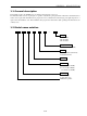
1.
CHAPTER 3 ADJUSTMENTS This printer is adjusted in a variety of ways to obtain the prescribed performance. This chapter explains those adjustments. When replacing parts during maintenance inspections or after a problem occurs, double check the adjustments afterwards. 3.1 Tools and Measuring Instruments ........................................................................ 3-1 3.2 Adjusting the Gap between the Print Head and the Platen .................................. 3-2 3.2.
CHAPTER 4 PARTS REPLACEMENT This chapter explains disassembly and reassembly of the printer. Note the following precautions during disassembly and reassembly. 1. Disconnect the printer power cord plug from the wall outlet before servicing it. 2. Assembly is the reverse of disassembly unless otherwise specified. 3. After reassembly, coat the screw heads with locking sealant. 4. Lubrication information is not provided in this chapter, Refer to Section 5.2 4.1 Upper Case Unit..................................
PARTS REPLACEMENT 4.1 Upper Case Unit 4-1 1. Turn off the power switch 1, disconnect the power cord from the wall outlet. 2. Remove • Four tapping screws 2.
PARTS REPLACEMENT 4.2 Printer Mechanism 1. 4-2 Remove • Upper case unit according to the procedure described in Section 4.
PARTS REPLACEMENT 4.3 Main Logic Board 1. Turn off the power switch, disconnect the power cord from wall outlet. 2. Remove • Printer Mechanism according to the procedure described in Section 4.2 3. Main Chassis 1 and Board Chassis 2 from Lower Case 3. 4. Remove • Cable unit and connector • Two screws(Main chassis) 4 • Two screws(Board) 5 • Two screws and spacers(interface connector) 6 • Main logic board 7 4.4 Power Supply Unit 1.
PARTS REPLACEMENT 4.5 Fuses 1. Remove • Printer supply unit according to the procedure described in Section4.4. 2. Inspect • F1 1 • F2 2 If a fuse is defective, replace with the correct type of fuse as listed below: Note:If the new fuse blows, inspect the circuit. *:Fuse F2 is to only be replaced with Bell Fuse Inc., Type 5TT3A, rated 3A, 125V. 4.6 Auto Cutter 4-4 1. Turn off the power switch, disconnect the power cord from wall outlet. 2.
PARTS REPLACEMENT 4.7 Print Head 1. Turn off the power switch, disconnect the power cord from wall outlet. 2. Remove • Upper case unit(not shown in the figure)according to the procedure described in Section 4.1. • Two screws 1 • Head cover 2 • Two tapping screws 3 • Head cable 4 • Print head 5 WARNING The print head becomes hot after printing so wait for it to cool before removing it. 3. Adjust • Gap between print head and platen (Refer to Section 3.2.
PARTS REPLACEMENT 4.9 Thermal Board Unit 1. Remove • Printer mechanism according to the procedure described in Section4.2. • The eleven soldered lead wires 1 with the soldering iron.(MP212/242) • The thirteen soldered lead wires 1 with the soldering iron.(MP216/246) • Two screws 2 • Thermal board unit 3 4.10 Carriage Motor Unit 1. Remove • Printer mechanism according to procedure described in Section 4.2. • Screw 1 and the ribbon base 2 after sliding blackarrow direction.
PARTS REPLACEMENT 1. Removal • Remove the printer mechanism according to the procedure of item 4.2. • Two solderd lead wires (Black and red) • Stop ring 1 • Gear 2 • Stop ring 3 • Slide the ribbon base (W) 4 in the direction of the black arrow and remove it. • Screw 5 • Secure the frame and forcibly open the carriage motor unit in the direction of the white arrow . • Carriage motor unit 6 2.
PARTS REPLACEMENT 4.12 Ribbon Color Change Mechanism (only for SP216/246) 4-8 1. Removal • Remove the printer mechanism according to the procedure of item 4.2. • Stop ring 1 • Gear 2 • Stop ring 3 • Slide the ribbon base (W) 4 in the direction of the black arrow and remove it. • Cam gear 5 • Stop ring 6 • RS cluttch unit 7 • Gear 12×24×0.4 8 • Gear 28×0.4 9 2. Adjustment • After assembling, adjust the cam position of the ribbon color change mechanism by referring to item 3.4.
CHAPTER 6 PARTS LIST HOW TO USE PARTS LIST 1. DRWG. NO. This column shows the drawing number of the illustration. 2. REVISED EDITION MARK This column shows a revision number. Parts that have been added in the revised edition are indicated with “#”. Parts that have been abolished in the revised edition are indicated with “*”. #1: First edition → Second edition #2: Second edition → Third edition *1: First edition → Second edition *2: Second edition → Third edition 3. PARTS NO.
PARTS LIST 6.1 Printer Assembly 6.1.1 Assembly Drawing A.
PARTS LIST B.
PARTS LIST C.
PARTS LIST D.
PARTS LIST 1 #1 38000210 38000610 MP212FP-24 MP216FP-24 1 1 6-5 SP212 SP216 S S
PARTS LIST Printer Assembly DRWG.NO. REV. PARTS NO.
PARTS LIST 6.2 Printer Mechanism 6.2.1 Assembly Drawing A.
PARTS LIST B.
PARTS LIST C.
PARTS LIST D.
PARTS LIST 6.2.2 Parts List DRWG.NO. REV. PARTS NO.
PARTS LIST Printer Mechanism DRWG.NO. REV. PARTS NO. 46 04020015 47 04020016 48 04020010 #1 04020010 51 *2 01902620 #2 01902631 52 00626404 53 00926503 #3 00926503 54 00926803 55 *2 01902617 #2 01902618 56 01902617 57 33100110 59 01902622 60 02205001 62 *2 37008320 #2 37008020 63 #1 33102120 67 #1 33100120 68 #1 33101310 70 #1 37006020 71 #1 37004010 72 #3 37002620 73 #3 37000560 74 #3 37000550 75 #3 30290110 76 #3 04991204 PARTS NAME STOP RING SE3.0 STOP RING SE4.0 STOP RING SE2.0 STOP RING SE2.
PARTS LIST 6.3 Sub-assembly 6.3.1 Upper Case Unit A. SP212/216 DRWG.NO. REV. PARTS NO.
PARTS LIST B. SP242/246 DRWG.NO. REV. PARTS NO.
PARTS LIST 6.3.2 Lower Case Unit DRWG.NO. REV. PARTS NO.
PARTS LIST 6.4 Wiring Schematic of Printer 6.4.
PARTS LIST 6.4.
PARTS LIST 6.5 Main Logic Board 6.5.1 For Serial Interface 6.5.1.
PARTS LIST 6-19
PARTS LIST 6-20
PARTS LIST 6-21
PARTS LIST 6.5.1.2 Parts List Main Logic Board (Serial Interface) DRWG.NO. REV. PARTS NO.
PARTS LIST Main Logic Board (Serial Interface) DRWG.NO. REV. PARTS NO. R61 R62 R63 R64-65 R66 R67-69 C1-3 C4 C5-8 C9 C10-12 C13 C14 C15 C16-17 C18 C19 C20 C21-22 C23 C24 C25 C26 C27-28 BC1 BC2-3 BC4 BC5-6 BC7 BC8-10 TA1-2 TR1 TR2 TR3 TR4-10 TR11 TR12 TR13 REG1 D1-2 D3 D4 LED1-2 RA1 RA2 RA3 RA4-5 RA6 RA7 RA8 RA9 06054725 06051051 06052211 06054725 06051535 06051034 PARTS NAME RD RD RD RD RD RD RESISTOR RESISTOR RESISTOR RESISTOR RESISTOR RESISTOR 4.7 K-OHM 1/6W 1 M-OHM 1/6W 220 OHM 1/6W 4.
PARTS LIST Main Logic Board (Serial Interface) DRWG.NO. REV. PARTS NO. CA1 05652212 CA2 05651012 CA3 05651018 CN1 09100566 CN2 09100567 CN3 09100495 CN4 09100317 CN5 DSW1 09090054 SW1-2 09010055 X1 09250047 L1 09990705 PARTS NAME CAPA. ARRAY 220PF 50V 8EL CAPA. ARRAY 100PF 50V 8EL CAPA. ARRAY 100PF 50V 7EL CONNECTOR 17JE-13250-37 CONNECTOR 95003-2661 CONNECTOR HLEM23S-1 CONNECTOR 5483-04A Q’TY 1 1 1 1 1 1 1 REMARKS NOT USED DIP SWITCH SD-10ZL PUSH SWITCH SKHHLN CERA. OSCILLATOR CST8.
PARTS LIST 6.5.2 For Parallel Interface 6.5.2.
PARTS LIST 6-26
PARTS LIST 6-27
PARTS LIST 6.5.2.2 Parts List Main Logic Board (Parallel Interface) DRWG.NO. REV. PARTS NO. IC1 IC2 *3 #3 IC3 IC4 IC5 IC6 IC7 IC8 IC9 R1 PARTS NAME Q’TY 08222026 08210142 08210126 08240072 EPROM 27256-150NS TTL IC 74LS05FP*TL TTL IC 74LS05FP*EL GATE ARRAY HG62E11R77FBSPII 1 1 1 1 08210127 TTL IC 74LS06FP*EL 1 08250018 CPU 1 M37732S4AFP 08200109 IC-RESET M51953BL 1 #3 06051535 RD RESISTOR 15 K-OHM 1/6W 1 #3 06053324 06055614 RD RESISTOR 3.
PARTS LIST Main Logic Board (Parallel Interface) DRWG.NO. REV. PARTS NO. R57-58 R59-60 R61 R62 R63 R64-65 R66 R67-69 R70-77 R78 R79 R80-83 R84 R85-87 R88 R89 R90 R91-92 C1 C2 C3 PARTS NAME RESISTOR RESISTOR RESISTOR RESISTOR RESISTOR RESISTOR RESISTOR Q’TY 06054725 06051034 06054725 06051051 06052211 06054725 06051535 RD RD RD RD RD RD RD 4.7 K-OHM 1/6W 10 K-OHM 1/6W 4.7 K-OHM 1/6W 1 M-OHM 1/6W 220 OHM 1/6W 4.7 K-OHM 1/6W 15 K-OHM 1/6W 2 2 1 1 1 2 1 06054725 06051025 06051014 RD RESISTOR 4.
PARTS LIST Main Logic Board (Parallel Interface) DRWG.NO. REV. PARTS NO.
PARTS LIST 6.6 Power Supply Unit 6.6.
PARTS LIST 6.6.2 Parts List DRWG.NO. REV. PARTS NO.
PARTS LIST 6.7 Terminal Board 6.7.
PARTS LIST 6.7.2 Parts List DRWG.NO. REV. PARTS NO.
ELECTRONIC PRODUCTS DIVISION STAR MICRONICS CO., LTD. 536 Nanatsushinya, Shimizu, Shizuoka, 424-0066 Japan Tel : 0543-47-0112 Fax : 0543-48-5271 OVERSEAS SUBSIDIARY COMPANIES STAR MICRONICS AMERICA, INC. 70-D Ethel Road West, Piscataway, NJ 08854 U.S.A Tel : 732-572-9512 Fax : 732-572-5095 STAR MICRONICS U.K. LTD. Star House, Peregrine Business Park, Gomm Road, High Wycombe, Bucks, HP13 7DL, U.K. Tel : 01494-471111 Fax : 01494-473333 Please access the following URL http://www.star-micronics.co.