DOT MATRIX PRINTER SP200F SERIES USER’S MANUAL MODE D’EMPLOI BEDIENUNGSANLEITUNG MANUALE DI ISTRUZIONI
Federal Communications Commission Radio Frequency Interference Statement This equipment has been tested and found to comply with the limits for a Class A digital device, pursuant to Part 15 of the FCC Rules. These limits are designed to provide reasonable protection against harmful interference when the equipment is operated in a commercial environment.
TABLE OF CONTENTS 1. Outline ............................................................................................................... 1 2. Unpacking and Installation ................................................................................ 2 2-1. Unpacking .............................................................................................. 2 2-2. Locating the printer ................................................................................ 3 2-3. Handling Care ................
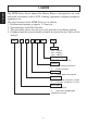
1. Outline ENGLISH The SP200 Series Serial Impact Dot Matrix Printer is designed for use with electronic instruments such as POS, banking equipment, computer peripheral equipment, etc. The major features of the SP200 Series are as follows: 1. Bi-directional printing at approx. 2.5 lines/sec. 2. Serial interface or Parallel interface. 3. The data buffer allows the unit to receive print data even during printing. 4. Peripheral unit drive circuit enables control of external devices such as cash drawers.
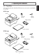
2-1. Unpacking After unpacking the unit, check that all the necessary accessories are included in the package. SP210 type Printer Ferrite core (EU only) Fastener (EU only) Ribbon cartridge User´s manual SP240 type Printer Ferrite core (EU only) Ribbon cartridge User´s manual Fig. 2-1 Unpacking –2– Fastener (EU only) ENGLISH 2.
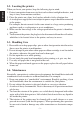
2-2. Locating the printer ENGLISH When you locate your printer, keep the following tips in mind: 1. Protect your printer from excessive heat such as direct sunlight or heaters, and keep it away from moisture and dust. 2. Place the printer on a firm, level surface which is fairly vibration-free. 3. A steady power supply that is not subject to power surges should be connected to the printer.
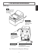
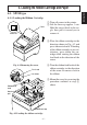
ENGLISH 3. Parts Identification and Nomenclature SP210 type Cover Protects the printer from dust and reduces noise. Do not open the cover while printing. Control panel Features two control switches and two indicators to indicate printer status. AC power cord Plugs into an outlet of the specified voltage. Shape of AC power plug will vary according to destinations. Interface connector Connects the printer with host computer.
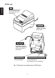
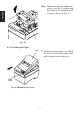
SP240 type ENGLISH Cover Protects the printer from dust and reduces noise. Do not open the cover while printing. Control panel Features two control switches and two indicators to indicate printer status. AC power cord Plugs into an outlet of the specified voltage. Shape of AC power plug will vary according to destinations. Interface connector Connects the printer with host computer. Peripheral unit drive circuit connector Connects to peripheral units such as cash drawers, etc.
4-1. SP210 type 4-1-1. Loading the Ribbon Cartridge Cover Power off 1 Turn off power to the printer. 2 Lift the cover up approx. 3 cm. Hold the cover tilted at this angle, then pull it toward you to remove it. 3 Place the ribbon cartridge in the direction shown in Fig. 4-2 and press it down to load it. If loading of the ribbon cartridge is not satisfactory, press down the cartridge while rotating the ribbon feed knob in the direction of the arrow. Fig.
ENGLISH Note: When removing the ribbon cartridge, raise the A section and then remove it by holding the B section as shown in Fig. 4-3. A B Fig. 4-3 4-1-2. Loading the Paper Cover 1 Lift the cover up approx. 3cm. Hold the cover tilted at this angle, then pull it toward you to remove it. FEED switch Fig.
Core Axis Paper roll holder Fig. 4-5 Loading the paper Positioning rib Cover Roll paper 2 Cut off the front edge of the roll paper perpendicularly. 3 Confirm that the power of the printer is turned on. 4 While observing the direction of the roll paper, insert the top end of the paper beneath the paper guide as far as it will go. If the roll paper is installed, the top end of the paper automatically comes out from the paper exit.
4-2. SP240 type 4-2-1. Loading the Ribbon Cartridge ENGLISH Cover Power off 1 Turn off power to the printer. 2 Lift the cover up approx. 3 cm. Hold the cover tilted at this angle, then pull it toward you to remove it. Fig. 4-8 Removing the cover 3 Lift up the auto cutter and put it in a vertical position, as shown in Fig. 4-9. Auto cutter Fig.
Ink ribbon Auto cutter Ribbon feed knob Notched part 4 Place the ribbon cartridge in the direction shown in Fig. 4-10 and press it down to load it. If loading of the ribbon cartridge is not satisfactory, press down the cartridge while rotating the ribbon feed knob in the direction of the arrow. 5 Turn the ribbon feed knob of the ribbon cartridge in the direction of the arrow to remove slack in the ribbon. 6 Close the Auto Cutter. Ribbon cartridge Fig.
4-2-2. Loading the Paper Cover ENGLISH 1 Lift the cover up approx. 3cm. Hold the cover tilted at this angle, then pull it toward you to remove it. FEED switch Fig. 4-12 Removing the cover Roll paper Core Axis Paper roll holder Fig. 4-13 Loading the paper 2 Cut off the front edge of the roll paper perpendicularly. 3 Confirm that the power of the printer is turned on. 4 While observing the direction of the roll paper, insert the top end of the paper beneath the paper guide as far as it will go.
Positioning rib Cover Roll paper Paper roll holder Fig. 4-14 Paper insertion slit Auto cutter 8 Insert the tip of the roll paper in the auto cutter paper slit. • When using copying paper, insert only the original (the upper paper) into the slit of the auto cutter. Insert the paper which is to be copied (the lower paper) between the platen and the auto cutter. Fig.
Auto cutter ENGLISH Paper insertion slit Upper paper Upper paper Paper insertion slit Lower paper Print head Platen Lower paper Print head Platen Fig. 4-16 Insertion of the paper into the auto cutter (When using copying paper) 9 Pull on the edge of the paper to remove any slack and then lower the auto cutter. 0 Insert the paper through the paper outlet and then replace the cover by reversing the removal steps.
Remove the cover, then cut off the paper near the rear of the paper guide and press the FEED switch to feed out the paper remaining in the unit. When the paper runs out, the POWER lamp will blink. Note 1. Remove the paper remaining in the printer by pressing the FEED switch. 2. When the paper end mark appears on the paper, replace the roll paper before it runs out. 3. When removing the core of the roll paper, open the roll paper holder. 4-4. Connecting the Interface Cable 4-4-1.
4-4-2. Serial Interface Cable ENGLISH Ferrite core (EU only) Screws Screwdriver Fig. 4-20 Connecting the interface cable 1 Turn off power to both the host computer and the printer. 2 Insert the connector at one end of the interface cable into the connector on the printer and the other connector into the connector for the host computer. 3 Next, fasten the right and left screws for the respective interface connectors to fix them in place on the connectors. 4-4-3.
5-1. Basic Operation POWER 3 4 ON LINE FEED 1 2 Fig. 5-1 Control panel 1 ON LINE switch Switches the printer between ON LINE and OFF LINE. ON LINE and OFF LINE switching is possible only when paper is loaded in the printer. 2 FEED switch • When this switch is pressed and then released within 0.5 sec., the paper feeds on line. • When this switch is held depressed for more than 0.5 sec., the paper feeds continuously. (The above paper feed operation is possible for both ON LINE and OFF LINE modes.
5-2. Switch Operation (Combined Switch Operation) ENGLISH 1 FEED + POWER ON (Turn the power on while holding the FEED switch depressed.) Self-printing will be performed according to the VER. NO., DIP switch settings and character order. When the FEED switch is held continuously or when the FEED switch is depressed at the time of the end of self-printing, only the characters will be printed out repeatedly. Fig.
Fig. 5-3 Hexadecimal dump printing sample – 18 – ENGLISH 2 ON LINE + POWER ON (Turn the power on while holding the ON LINE switch depressed.) Each of the signals sent from the computer to the printer will be printed out in hexadecimal code. This function allows you to check if a control code sent to the printer by the program being used is correct or not. The last line is not printed if its data is less than one full line.
6. Control Codes ENGLISH STAR mode 6-1. Control Codes Used in Character Setting Control codes Hexadecimal codes Function “R” n 1B 52 n Select international character set. Default is according to the dip switch settings 3, 4 and 5.
Control codes Hexadecimal codes Function n1 n2 1B 07 n1 n2 Adjust drive pulse width for peripheral unit (Default setting) 07 Deferred drive command “A” for peripheral unit 1 1C Immediate drive command “B” for peripheral unit 1 6-5.
ENGLISH – 21 –
1. Introduction ..................................................................................................... 23 2. Déballage et Inspection ................................................................................... 24 2-1. Déballage ............................................................................................. 24 2-2. Emplacement de l’imprimante .............................................................25 2-3. Précautions de manipulation ...................................
1. Introduction FRANÇAIS L’imprimante série à impact et matrice de points est conçue pour une utilisation avec des instruments électroniques tels que des terminaux points de vente, du matériel bancaire, du matériel périphérique pour ordinateurs, etc. Les caractéristiques principales des modèles de la série SP200 sont les suivantes: 1. Impression bi-directionnelle à 2,5 lignes/sec. environ. 2. Interface série ou parallèle. 3.
2. Déballage et Inspection 2-1. Déballage FRANÇAIS Après avoir déballé l’appareil, vérifiez si tous les accessoires nécessaires se trouvent dans la boîte. Modèle SP210 Imprimante Tore de ferrite (UE seulement) Attache (UE seulement) Cartouche à ruban Mode d’emploi Modèle SP240 Imprimante Tore de ferrite (UE seulement) Cartouche à ruban Mode d’emploi Fig.
2-2. Emplacement de l’imprimante FRANÇAIS Pour installer correctement l’imprimante, gardez à l’esprit les conseils suivants: 1. Mettez l’imprimante à l’abri de températures excessivement élevées comme en plein soleil ou à proximité d’un appareil de chauffage, et à l’abri de l’humidité et de la poussière. 2. Installez l’imprimante sur une surface stable et de niveau sur laquelle l’imprimante ne sera pas soumise à des vibrations. 3. Veillez à ce que l’imprimante soit branchée sur une source secteur stable.
3. Identification des Pièces et Nomenclature Modèle SP210 FRANÇAIS Capot Protège l’imprimante de la poussière et réduit le bruit. Ne pas ouvrir le capot pendant l’impression. Panneau de commande Comprend deux commutateurs de commande et trois témoins indiquant le statut de l’imprimante. Cordon d’alimentation secteur A brancher sur la sortie correspondant à la tension spécifiée. La présentation de la fiche du cordon d’alimentation secteur varie selon les pays.
Modèle SP240 Capot Protège l’imprimante de la poussière et réduit le bruit. Ne pas ouvrir le capot pendant l’impression. FRANÇAIS Panneau de commande Comprend deux commutateurs de commande et deux témoins indiquant le statut de l’imprimante. Cordon d’alimentation secteur A brancher sur la sortie correspondant à la tension spécifiée. La présentation de la fiche du cordon d’alimentation secteur varie selon les pays.
4. Installation d’une cartouche à ruban et chargement du papier 4-1. Modèle SP210 Capot Hors tension 1 Mettez l’imprimante hors tension. 2 Soulevez le capot d’environ 3 cm. Tout en tenant le couvercle incliné à cet angle, tirez-le vers vous pour l’enlever. 3 Mettez la cartouche à ruban en place dans le sens indiqué dans la figure 4-2 et appuyez légèrement sur la cartouche afin qu’elle se mette en place.
Remarque: Pour enlever la cartouche à ruban, soulevez la partie A, puis enlevez la cartouche en la tenant par la partie B comme indiqué dans la figure 4-3. A FRANÇAIS B Fig. 4-3 4-1-2. Chargement du papier Capot 1 Soulevez le capot d’environ 3 cm. Tout en tenant le couvercle incliné à cet angle, tirez-le vers vous pour l’enlever. Touche d’avance de papier (FEED) Fig.
2 Coupez l’extrémité du papier perpendiculairement. 3 Vérifiez si l’imprimante est bien sous tension. 4 Insérez l’extrémité du papier sous le guide de papier aussi loin que possible en faisant attention au sens du rouleau. Tube central Lorsque le rouleau est en place, le papier ressort automatiquement par la fente de sortie de l’imprimante.
4-2. Modèle SP240 4-2-1. Installation d’une cartouche à ruban Capot FRANÇAIS Hors tension 1 Mettez l’imprimante hors tension. 2 Soulevez le capot d’environ 3 cm. Tout en tenant le couvercle incliné à cet angle, tirez-le vers vous pour l’enlever. Fig. 4-8 Dépose du capot Unité de découpage automatique Fig. 4-9 Redressement de l’unité de découpage automatique – 31 – 3 Soulevez l’unité de découpage automatique pour la mettre en position verticale, comme indiqué dans la figure 4-9.
Ruban encreur Unité de découpage automatique Bouton d’alimentation du ruban Parties avec encoches 4 Mettez la cartouche à ruban en place dans le sens indiqué dans la figure 4-10 et appuyez légèrement sur la cartouche afin qu’elle se mette en place. Si la mise en place de la cartouche n’est pas satisfaisante, appuyez sur la cartouche tout en faisant tourner le bouton d’alimentation du ruban de la cartouche dans le sens de la flèche.
4-2-2. Chargement du papier Capot 1 Soulevez le capot d’environ 3 cm. Tout en tenant le couvercle incliné à cet angle, tirez-le vers vous pour l’enlever. FRANÇAIS Touche d’avance de papier (FEED) Fig. 4-12 Dépose du capot 2 Coupez l’extrémité du papier perpendiculairement. 3 Vérifiez si l’imprimante est bien Rouleau de papier sous tension. 4 Insérez l’extrémité du papier sous le guide de papier aussi loin que possible en faisant attention au sens du rouleau.
7 Appuyez sur la touche d’avance FEED pour faire avancer le papier de 10 cm environ. Nervure de positionnement FRANÇAIS Capot Rouleau de papier Support de rouleau de papier Fig. 4-14 Fente d’insertion du papier Unité de découpage automatique Fig. 4-15 Insertion du papier dans l’unité de découpage automatique 8 Insérez l’extrémité du papier dans la fente de l’unité de découpage automatique.
Fente d’insertion du papier Feuille supérieure Unité de découpage automatique Feuille supérieure Fente d’insertion du papier Feuille inférieure FRANÇAIS Tête d’impression Cylindre Feuille inférieure Tête d’impression Cylindre Fig. 4-16 Insertion du papier dans l’unité de découpage automatique (avec utilisation de papier pour copie) Sortie de papier Unité de découpage automatique 9 Tirez sur l’extrémité du papier afin de tendre le papier, puis rabaissez l’unité de découpage automatique.
4-3. Enlèvement d’un rouleau de papier Remarques 1. Enfoncez la touche d’avance FEED pour retirer le reste du papier qui se trouve dans l’imprimante. 2. N’attendez pas que le rouleau de papier soit épuisé avant de le remplacer. Remplacez-le dès que le repère de fin de rouleau apparaît. 3. Pour enlever le tube du rouleau de papier, ouvrez le support de rouleau de papier. 4-4. Connexion du câble d’interface 4-4-1.
4-4-2. Câble d’interface série 1 Mettez l’ordinateur hôte et l’imprimante hors tension. 2 Insérez un des connecteurs du câble d’interface dans la prise de l’imprimante et l’autre dans la prise de l’ordinateur hôte. 3 Serrez ensuite les vis droite et gauche des connecteurs pour les fixer aux prises. Tore de ferrite (UE seulement) FRANÇAIS Vis Tournevis Fig. 4-20 Connexion du câble d’interface série 4-4-3. Câble d’interface parallèle Tore de ferrite (UE seulement) Fig.
5. Panneau de Commande 5-1. Fonctionnement de base 1 Touche ON LINE Cette touche permet de mettre l’imprimante en ligne ou hors ligne. Vous ne pouvez effectuer cette commutation que si du papier est chargé dans l’imprimante. 3 4 1 2 2 Touche d’avance FEED • Si vous appuyez sur cette touche, Fig. 5-1 Panneau de commande puis la relâchez moins de 0,5 seconde après, le papier avancera d’une ligne à la fois.
5-2. Utilisation des touches (Utilisation combinée des touches) FRANÇAIS 1 FEED + POWER ON (Mettez l’imprimante sous tension tout en maintenant la touche FEED enfoncée.) Le test d’impression sera effectué conformément au réglage du numéro de vérification, des commutateurs DIP et de l’ordre des caractères. Si vous maintenez la pression sur la touche FEED ou si vous appuyez sur la touche FEED à la fin du test d’impression, seuls les caractères seront imprimés à plusieurs reprises. Fig.
Fig. 5-3 Exemple d’impression d’essai avec vidage hexadécimal – 40 – FRANÇAIS 2 ON LINE + POWER ON (Mettez l’imprimante sous tension tout en maintenant la touche ON LINE enfoncée.) Chacun des signaux envoyés de l’ordinateur à l’imprimante sera imprimé en code hexadécimal. Cette fonction vous permet de vérifier si un code de contrôle envoyé à l’imprimante par le programme utilisé est correct ou non.
6. Codes de contrôle Mode STAR 6-1. Commandes utilisées pour le réglage des caractères FRANÇAIS Code de contrôle Code hexadécimal Fonction “R” n 1B 52 n Sélection du jeu de caractères internationaux. Le réglage par défaut est fonction du réglage des commutateurs DIP 3, 4 et 5.
Code de contrôle Code hexadécimal Fonction n1 n2 1B 07 n1 n2 Réglage de la largeur d’impulsion d’entraînement du périphérique (réglage par défaut) 07 Commande d’entraînement différé “A” de l’appareil périphérique 1 1C Commande d’entraînement immédiat “B” de l’appareil périphérique 1 6-5.
FRANÇAIS – 43 –
1. Kurzbeschreibung ............................................................................................ 45 2. Auspacken und Aufstellen ...............................................................................46 2-1. Überprüfen ...........................................................................................46 2-2. Wahl eines Aufstellungsorts für den Drucker ...................................... 47 2-3. Hinweise zum Umgang ............................................................
1. Kurzbeschreibung Der serielle Nadeldrucker der Serie SP200 ist zur Verwendung mit elektronischen Instrumenten wie POS, Bankgeräte, Computerzubehör, etc. gedacht. Die wichtigsten Merkmale der Serie SP200 sind: 1. Bidirektioneller Druck mit ca. 2,5 Zeilen/s 2. Serielle oder parallele Schnittstelle 3. Pufferspeicher erlaubt, Druckdaten auch während des Druckvorgangs zu empfangen. 4.
2. Auspacken und Aufstellen 2-1. Überprüfen Sie den Kartoninhalt, und vergewissern Sie sich, daß alle unten abgebildeten Teile vorhanden sind. Typ SP210 Ferritkern (nur EU) Befestigungsband (nur EU) Farbbandkassette Bedienungsanleitung Typ SP240 Drucker Ferritkern (nur EU) Befestigungsband (nur EU) Farbbandkassette Bedienungsanleitung Abb.
2-2. Wahl eines Aufstellungsorts für den Drucker DEUTSCH Bevor Sie den Drucker auspacken, sollten Sie einige Minuten damit verbringen, einen geeigneten Aufstellungsort auszusuchen. Denken Sie dabei an die folgenden Punkte: 1. Den Drucker vor Hitzequellen wie direktem Sonnenlicht oder Heizkörpern schützen und von Feuchtigkeit und Staub fernhalten. 2. Den Drucker auf einem flachen, aber festen Untergrund aufstellen, wo keine Vibrationen vorhanden sind. 3.
3. Beschreibung und Bezeichnung der Geräteteile Typ SP210 Bedienfeld Hat zwei Bedienungstasten und zwei Anzeigen zur Anzeige des Druckerzustands. Netzkabel Zum Anschluß an eine Netzbuchse. Der Stecker ist je nach Bestimmungsland unterschiedlich ausgelegt. Schnittstellenbuchse Zum Anschluß des Druckers an den Hostcomputer. Peripheriegerät-Steueranschluß Zum Anschluß an Peripheriegeräte wie Registrierkassen etc. Nicht zum Anschluß an ein Telefon! Abb.
Typ SP240 Abdeckung Schützt den Drucker vor Staub, und reduziert das Betriebsgeräusch. Nicht die Frontabdeckung während des Druckens öffnen. DEUTSCH Bedienfeld Hat zwei Bedienungstasten und zwei Anzeigen zur Anzeige des Druckerzustands. Netzkabel Zum Anschluß an eine Netzbuchse. Der Stecker ist je nach Bestimmungsland unterschiedlich ausgelegt. Schnittstellenbuchse Zum Anschluß des Druckers an den Hostcomputer. Peripheriegerät-Steueranschluß Zum Anschluß an Peripheriegeräte wie Registrierkassen etc.
4. Einlegen von Farbbandkassette und Papier 4-1. Typ SP210 4-1-1. Einlegen der Farbbandkassette Netzschalter aus 3 Die Farbbandkassette in der Richtung einsetzen wie in der Abbildung 4-2 gezeigt und eindrükken, bis sie hörbar einrastet. Wenn die Farbbandkassette nicht richtig sitzt, eingedrückt halten und gleichzeitig den Farbbandknopf in Pfeilrichtung drehen. 4 Um Schlaufen im Farbband aufzuwickeln, den Farbbandzuführknopf der Farbbandkassette in Pfeilrichtung drehen. Abb.
Hinweis: Beim Entfernen der Farbbandkassette den Teil A anheben und dann die Kassette an Teil B halten und Abziehen wie in Abbildung 4-3 gezeigt. A DEUTSCH B Abb. 4-3 4-1-2. Einlegen von Papier Abdeckung 1 Die Abdeckung um etwa 3 cm anheben. Die Abdeckung in diesem Winkel halten, und dann zum Entfernen nach vorne ziehen. FEEDTaste Abb.
2 Schneiden Sie die Vorderkante des Rollenpapiers in einer geraden Linie ab. 3 Bestätigen Sie, daß der Drucker eingeschaltet ist. 4 Unter Beachtung der Richtung des Rollenpapiers führen Sie die Vorderkante des Papiers unter der Papierführung so weit Kern wie möglich ein. Wenn die Rolle einglegt ist, kommt das Vorderende des Papiers Achse automatisch aus dem Papierauslaufschlitz.
4-2. Typ SP240 4-2-1. Einlegen der Farbbandkassette Frontabdeckung Netzschalter aus 1 Stellen Sie den Netzschalter am Drucker in Aus-Stellung. 2 Zum Abnehmen der Frontabdeckung heben Sie diese ca. 3 cm an, und ziehen sie dann nach vorne. DEUTSCH Abb. 4-8 Abdeckung abnehmen 3 Heben Sie das Schneidwerk an und stellen es in senkrechte Stellung, wie in Abbildung 4-9 gezeigt. Schneidwerk Abb.
Druckkopf Farbband Schneidwerk Farbbandknopf 4 Die Farbbandkassette in der Richtung einsetzen wie in der Abbildung 4-10 gezeigt und eindrükken, bis sie hörbar einrastet. Wenn die Farbbandkassette nicht richtig sitzt, eingedrückt halten und gleichzeitig den Farbbandknopf in Pfeilrichtung drehen. 5 Um Schlaufen im Farbband aufzuwickeln, den Farbbandzuführknopf der Farbbandkassette in Pfeilrichtung drehen. 6 Das Schneidwerk schließen. Farbbandkassette Abb.
4-2-2. Einlegen von Papier Abdeckung 1 Die Abdeckung um etwa 3 cm anheben. Die Abdeckung in diesem Winkel halten, und dann zum Entfernen nach vorne ziehen. DEUTSCH FEEDTaste Abb. 4-12 Entfernen der Abdeckung Rollenpapier Kern Achse Papierrollenhalter Abb. 4-13 Einlegen des Papiers 2 Schneiden Sie die Vorderkante des Rollenpapiers in einer geraden Linie ab. 3 Bestätigen Sie, daß der Drucker eingeschaltet ist.
7 Drücken Sie die FEED-Taste (Papiervorschub), um das Papier um ca. 10 cm vorzuschieben. Positionierrippe Abdeckung DEUTSCH Rollenpapier Papierrollenhalter Abb. 4-14 Papiereinführschlitz Schneidwerk Abb. 4-15 Einführen des Papiers in das Schneidwerk 8 Führen Sie die Oberkante des Papiers in den Schlitz des PapierSchneidwerks ein. • Bei Verwendung von Durchschlagpapier führen Sie nur das Original (den oberen Teil) in den Schlitz des Schneidwerks ein.
Schneidwerk Papiereinführschlitz Oberes Papier Druckkopf Oberes Papier Papiereinführschlitz Unteres Papier Druckwalze Unteres Papier Druckkopf Druckwalze DEUTSCH Abb. 4-16 Einführen des Papiers in das Schneidwerk (bei Verwendung von Durchschlagpapier) Papierauslaß 9 Ziehen Sie die Kante des Papierstau, um Schlaufen zu beseitigen, und senken Sie dann das Schneidwerk ab.
4-3. Entfernen des Rollenpapiers Nehmen Sie die Abdeckung ab, und schneiden Sie das Papier in der Nähe der Papierführung ab. Dann drücken Sie die FEED-Taste, um den Rest des Papiers auszugeben, der noch in der Einheit ist. Wenn das Papier verbraucht ist, blinkt das Lämpchen POWER. 4-4. Anschließen des Schnittstellenkabels 4-4-1.
4-4-2. Serielles Schnittstellenkabel 1 Schalten Sie sowohl den Hostcomputer als auch den Drucker aus. 2 Stecken Sie den Stecker des Schnittstellenkabels in die entsprechenden Buchsen am Drucker und am Hostcomputer ein. 3 Ziehen Sie die linken und rechten Schrauben an den Steckern fest, um den festen Sitz des Steckers zu sichern. Ferritkern (nur EU) Schrauben Schraubenzieher DEUTSCH Abb. 4-20 Anschließen des Schnittstellenkabels 4-4-3. Paralleles Schnittstellenkabel Ferritkern (nur EU) Abb.
5. Bedienfeld POWER 3 4 ON LINE FEED 1 2 Abb. 5-1 Bedienfeld 1 Taste ON LINE Schaltet den Drucker zwischen Online und Off-line Betrieb um. Umschalten ist nur möglich, wenn Papier im Drucker eingelegt ist. 2 FEED-Taste • Wenn diese Taste gedrückt und dann innerhalb von 0,5 s losgelassen wird, wird das Papier um eine Zeile vorgeschoben. • Wenn diese Taste länger als 0,5 s gedrückt gehalten wird, wird das Papier kontinuierlich vorgeschoben.
5-2. Tastenbedienung (kombinierte Tastenbedienung) 1 FEED + POWER ON (Gerät einschalten, während die Taste FEED gedrückt gehalten wird.) Der Selbstdruck wird entsprechend der VER.NO. DIP-Schaltereinstellung und der Zeichenfolge ausgeführt. Wenn die Taste FEED kontinuierlich gedrückt gehalten wird oder wenn FEED am Ende des Selbstdrucks gedrückt wird, werden nur die Zeichen wiederholt ausgedruckt. DEUTSCH Abb.
Abb. 5-3 Beispiel für sedezimalen Datenausdruck – 62 – DEUTSCH 2 ON LINE + POWER ON (Gerät einschalten, während die Taste ONLINE gedrückt gehalten wird.) Bei diesem Befehle werden alle Codes (Zeichencodes und Steuercodes), die vom Computer zum Drucker gesandt werden, in sedezimaler Form ausgedruckt. Der sedezimale Datenausdruck ist nützlich, um zu prüfen, ob vom Drucker ausgegebene Steuercodes richtig sind.
6. Steuercodes STAR-Modus 6-1. Steuercodes für Zeicheneinstellung Steuercodes Sedezimalcodes Funktion “R” n 1B 52 n Wählt internationalen Zeichensatz. Vorgabe-Einstellung ist entsprechend DIP-Schalter-Einstellung 3, 4 und 5.
6-4.
DEUTSCH – 65 –
L’Appendice appare solo nella sezione in inglese di questo manuale. – 66 – ITALIANO INDICE 1. Descrizione ......................................................................................................67 2. Disimballaggio e installazione ........................................................................68 2-1. Disimballaggio .....................................................................................68 2-2. Collocazione della stampante ...............................................
1. Descrizione La stampante seriale a matrice di impunti a impatto SP200 è stata progettata per l’uso con strumenti elettronici come POS, apparecchiature bancarie, periferiche computer, ecc. Le principali caratteristiche della serie SP200 sono come segue: 1. Stampa bidirezionale a circa 2,5 righe/sec. 2. Interfaccia seriale o interfaccia parallelo 3. Buffer dati per la ricezione di dati di stampa anche durante la stampa 4.
2. Disimballaggio e installazione 2-1. Disimballaggio Dopo aver disimballato l’unità, controllare che tutti gli accessori necessari siano inclusi nella confezione. Tipo SP210 Stampante Anello di ferrite (solo UE) Fascetta di fissaggio (solo UE) ITALIANO Cartuccia nastro Manuale di istruzioni Tipo SP240 Stampante Anello di ferrite (solo UE) Fascetta di fissaggio (solo UE) Cartuccia nastro Manuale di istruzioni Fig.
2-2. Collocazione della stampante Quando si colloca la stampante, tenere presenti le seguenti considerazioni: 1. Proteggere la stampante da calore eccessivo come luce solare diretta o caloriferi e tenerla lontana da umidità e polvere. 2. Collocare la stampante su una superficie stabile e piana che non sia soggetta a vibrazioni. 3. Collegare alla stampante una fonte di alimentazione stabile che non sia soggetta a picchi.
3. Identificazione delle parti e nomenclatura Tipo SP210 Pannello comandi Dispone di due interruttori di controllo e due indicatori dello stato della stampante. Cavo di alimentazione CA Collegarlo ad una presa a muro della tensione specificata. La forma della spina del cavo di alimentazione CA varia a seconda del paese di destinazione. Connettore interfaccia Per collegare la stampante al computer ospite.
Tipo SP240 Coperchio Protegge la stampante dalla polvere e riduce il rumore. Non aprire il coperchio durante la stampa. Pannello comandi Dispone di due interruttori di controllo e due indicatori dello stato della stampante. ITALIANO Cavo di alimentazione CA Collegarlo ad una presa a muro della tensione specificata. La forma della spina del cavo di alimentazione CA varia a seconda del paese di destinazione. Connettore interfaccia Per collegare la stampante al computer ospite.
4. Inserimento della cartuccia nastro e della carta 4-1. Tipo SP210 4-1-1. Inserimento della cartuccia nastro 3 Inserire la cartuccia nastro nella direzione mostrata nella Fig. 4-2 e premerla in basso per caricarla. Se il caricamento della cartuccia nastro non è soddisfacente, premere in basso la cartuccia nastro girando la manopola di avanzamento nastro in direzione della freccia. Fig.
Nota: Quando si rimuove la cartuccia nastro, sollevare la parte A e quindi rimuovere la cartuccia tenendo la parte B come mostrato nella Fig. 4-3. A B Fig. 4-3 ITALIANO 4-1-2. Inserimento della carta Coperchio 1 Sollevare il coperchio di 3 cm circa. Tenere il coperchio inclinato a questa angolazione e tirarlo verso di sè per rimuoverlo. Interruttore FEED Fig.
Anima di cartone Asse Supporto rotolo carta Fig. 4-5 Inserimento della carta Costa di posizionamento Coperchio Rotolo di carta 2 Tagliare perpendicolarmente l’estremità iniziale della carta del rotolo. 3 Verificare che la stampante sia accesa. 4 Osservando la direzione della carta del rotolo, inserire l’estremità superiore della carta sotto la guida della carta il più possibile. Se il rotolo carta è installato, l’estremità superiore della carta fuoriesce automaticamente dall’uscita carta.
4-2. Tipo SP240 4-2-1. Inserimento della cartuccia nastro Spegnere 1 Spegnere la stampante. 2 Sollevare il coperchio di 3 cm Coperchio circa. Tenere il coperchio inclinato a questa angolazione e tirarlo verso di sè per rimuoverlo. ITALIANO Fig. 4-8 Rimozione del coperchio Taglierina automatica Fig. 4-9 Sollevamento della taglierina automatica – 75 – 3 Sollevare la taglierina automatica e collocarla in posizione verticale, come mostrato nella Fig. 49.
Testina di stampa Nastro inchiostrato Taglierina automatica Manopola di avanzamento nastro Parte incassata 4 Inserire la cartuccia nastro nella direzione mostrata nella Fig. 410 e premerla in basso per caricarla. Se il caricamento della cartuccia nastro non è soddisfacente, premere in basso la cartuccia nastro girando la manopola di avanzamento nastro in direzione della freccia.
4-2-2. Inserimento della carta Coperchio 1 Sollevare il coperchio di 3 cm circa. Tenere il coperchio inclinato a questa angolazione e tirarlo verso di sè per rimuoverlo. Interruttore FEED ITALIANO Fig. 4-12 Rimozione del coperchio Rotolo di carta Anima di cartone Asse Supporto rotolo carta Fig. 4-13 Inserimento della carta 2 Tagliare perpendicolarmente l’estremità iniziale della carta del rotolo. 3 Verificare che la stampante sia accesa.
7 Premere l’interruttore FEED (avanzamento carta) per far avanzare la carta di circa 10 cm. Costa di posizionamento Coperchio Rotolo di carta Supporto rotolo carta Fessura di inserimento carta Taglierina automatica 8 Inserire l’estremità superiore della carta nella fessura carta della taglierina automatica. • Quando si usa carta autocopiante, inserire solo l’originale (il foglio superiore) nella fessura della taglierina automatica.
Taglierina automatica Fessura di inserimento carta Foglio superiore Fessura di inserimento carta Foglio superiore Testina di stampa Foglio inferiore Rullo Foglio inferiore Testina di stampa Rullo Fig. 4-16 Inserimento della carta nella taglierina automatica (quando si usa carta autocopiante) ITALIANO 9 Tirare il bordo del carta per eliminare eventuali allentamenti e quindi abbassare la taglierina automatica.
4-3. Rimozione della carta Rimuovere il coperchio, quindi tagliare la carta vicino al retro della guida carta e premere l’interruttore FEED per far fuoriuscire la carta rimanente nell’unità. Quando la carta è finita la spia POWER lampeggia. Nota 1. Rimuovere la carta rimanente nella stampante premendo l’interruttore FEED. 2. Quando il segno di fine carta appare sulla carta, sostituire il rotolo di carta prima che finisca. 3. Quando si rimuove l’anima di cartone del rotolo, aprire il supporto rotolo carta.
4-4-2. Cavo interfaccia seriale Anello di ferrite (solo UE) Viti Cacciavite 1 Spegnere sia il computer ospite che la stampante. 2 Inserire il connettore ad un capo del cavo interfaccia nel connettore sulla stampante e l’altro connettore nel connettore sul computer ospite. 3 Fissare le viti destra e sinistra dei rispettivi connettori interfaccia per fissare in posizione i connettori. Fig. 4-20 Collegamento del cavo interfaccia 4-4-3. Cavo interfaccia parallelo ITALIANO Anello di ferrite (solo UE) Fig.
5. Pannello comandi POWER 3 4 ON LINE FEED 1 2 Fig. 5-1 Pannello comandi 1 Interruttore ON LINE Alterna lo stato della stampante tra “on-line” e “off-line”. La commutazione tra “on-line” e “offline” è possibile solo quando c’è carta inserita nella stampante. 2 Interruttore FEED • Quando si preme questo interruttore e lo si rilascia entro 0,5 sec., la carta avanza di una riga. • Quando si tiene premuto questo interruttore per più di 0,5 sec., la carta avanza continuamente.
5-2. Operazioni con gli interruttori (operazioni combinate degli interruttori) 1 FEED + POWER ON (accendere tenendo premuto l’interruttore FEED) La stampa automatica viene eseguita secondo le impostazioni degli interruttori VER NO., DIP e l’ordine dei caratteri. Se si tiene premuto l’interruttore FEED o se si preme l’interruttore FEED alla fine della stampa automatica, solo i caratteri sono stampati ripetutamente. ITALIANO Fig.
Fig. 5-3 Esempio di stampa a scaricamento esadecimale – 84 – ITALIANO 2 ON LINE + POWER ON (accendere tenendo premuto l’interruttore ON LINE ) Ciascuno dei segnali inviati dal computer alla stampante viene stampato in codice esadecimale. Questa funzione permette di controllare se un codice di controllo inviato alla stampante dal programma usato è corretto o meno. L’ultima riga non viene stampata se i suoi dati non consistono di una riga completa.
6. Codici di controllo Modo STAR 6-1. Codici di controllo usati nell’impostazione dei caratteri Codici di controllo Codici esadecimali Funzione “R” n 1B 52 n Seleziona il gruppo caratteri internazionale. Il default è in base all’impostazione degli interruttori Dip 3, 4 e 5.
6-4.
Appendix A: Serial Interface A-1. Connectors and Signals RS-232C Pin no. Signal name 1 F-GND 2 N/C 3 RXD 4 RTS I/O direction — IN OUT APPENDIX 5-6 7 8-10 11 N/C S-GND N/C RCH OUT 12 13 14 N/C GND FAULT — OUT 15-19 20 N/C DTR OUT 21-25 N/C — Function Frame ground Not connected Received data Data transmission request signal. This is always “SPACE” when the printer is turned on.
A-2. Interface Connections The following is a basic example of interface connections. (For interface connections, refer to the specifications for the respective interface.
A-3. Dip Switch Setting Each of the switches in the DIP switch array is factory preset to ON. Be sure to turn the power to both the printer and host computer off before changing the setting of the DIP switches. The dip switch array will appear when the ROM cover is removed. ROM cover Power off DIP switch 1 ON 10 OFF Fig.
Data transmission rate (baud rate) Baud rate 1200 2400 4800 9600 Switch 6 OFF OFF ON ON Switch 7 OFF ON OFF ON A-4. Communication Protcol Signals are controlled using the DTR line as BUSY flag. Data Data RXD Buffer full Data Buffer empty DTR Printing APPENDIX Power on when paper is out RXD OFF LINE ON LINE DTR When printing Paper end Press the ONLINE button after loading paper.
buffer is below 256 bytes. After the host computer detects that the DTR signal line is at “MARK”, transmission of the data text is stopped. In this instance, data can still be received up until the data buffer becomes completely full. When the empty space in the data buffer is increased by following printing (when the data in the data buffer is reduced to 256 bytes or less), the printer sets the DTR signal line to “SPACE”.
Appendix B: Parallel Interface B-1. Interface Specifications The operating specifications of the parallel interface are as follows. (1) Data transfer rate : 1000 to 6000 characters per second (2) Synchronization : Via externally supplied STROBE pulses (3) Handshaking : ACK and BUSY signals (4) Logic level : Compatible with TTL level B-2. Interface Timing ACK Approx.9 µs Data STROBE T T BUSY T:more than 0.5 µs Fig.
B-3. Connectors and Signals Pin No. Signal Name 1 STROBE IN/OUT IN APPENDIX 2-9 DATA1-8 IN 10 ACK OUT 11 BUSY OUT 12 PAPER OUT OUT 13 14-15 16 17 18 19-30 31 SELECTED N/C SIGNAL GND CHASSIS GND +5VDC GND RESET OUT 32 ERROR OUT 33 34 35 36 EXT GND OUT1 N/C OUT IN Function Signals when data is ready to be read. Signal goes from HIGH to LOW (for at least 0.5 microsec.) when data is available. These signals provide the information of the first to eighth bits of parallel data.
B-4. Dip Switch Setting Each of the switches in the DIP switch array is factory preset to ON. Be sure to turn the power to both the printer and host computer off before changing the setting of the DIP switches. The dip switch array will appear when the ROM cover is removed. The ROM cover should be returned to its original position after DIP switch setting.
Appendix C: Peripheral Unit Drive Circuit A drive circuit for driving peripheral units (such as cash drawers) is featured on the main logic board of this printer. A modular connector for driving peripheral unit is featured on the output side on the drive circuit. When using this circuit, connect the cable for the peripheral unit. (Cables must be prepared by the user.) Note: Peripheral unit drive circuit connector only connects to peripheral units such as cash drawers, etc. Do not connect it to a telephone.
2 Drive circuit TR: D2010 F.G. 1 With shield 2 TR D VH 6 L Cash drawer 3 1 7824 6-P modular jack connector 4 M-GND Drive output 24V, max. 1.0 A APPENDIX Fig.
Appendix D: General Specifications Printing method: Print direction: Number of head pins: Number of print columns: Character set: Font configuration Serial impact dot matrix Bi-directional 7 wires 42 columns, 16 CPI ASCII 96 (characters) Special characters 64 IBM special characters 83 International characters 12 7 (Half dots) × 7 or 9 (Half dots) × 7 Paper width 3.
Ribbon material: Ribbon life: Interface Serial interface: Parallel interface: Data buffer: Peripheral unit drive circuit: Overall dimensions: Weight: Power Supply: AC power cable: Power consumption: Ambient temperature/humidity Operating temperature: Operating humidity: Storage temperature: Storage humidity: Mechanism reliability: Print head life: Accessory 300,000 cut (MCBF) Cartridge cassette SP212/242 type: Single color (Purple or black) SP216/246 type: Two color (Black and red) Nylon 66 (#40 denier)
158 SP210 Type 193 234 240 193 APPENDIX 158 SP240 Type Fig.
Appendix E: Character Font Table APPENDIX E-1. U.S.A.
APPENDIX – 101 –
APPENDIX E-2.
APPENDIX – 103 –
APPENDIX E-3.
E-4.
– 106 – APPENDIX
OVERSEAS SUBSIDIARY COMPANIES STAR MICRONICS AMERICA, INC. ELECTRONIC PRODUCTS DIVISION STAR MICRONICS CO., LTD. 536 Nanatsushinnya, Shimizu, Shizuoka, 424-0066 Japan Tel: 0543-47-0112, Fax: 0543-48-5271 1150 King Georges Post Road, Edison, NJ 08837-3729 U.S.A. Tel: 732-623-5555, Fax: 732-623-5590 STAR MICRONICS U.K. LTD. Star House, Peregrine Business Park, Gomm Road, High Wycombe, Bucks, HP13 7DL, U.K. Tel: 01494-471111, Fax: 01494-473333 Please access the following URL http://www.star-micronics.co.