SLIP PRINTER SP298 SERIES USER’S MANUAL MODE D’EMPLOI BEDIENUNGSANLEITUNG MANUALE DI ISTRUZIONI
Federal Communications Commission Radio Frequency Interference Statement This equipment has been tested and found to comply with the limits for a Class A digital device, pursuant to Part 15 of the FCC Rules. These limits are designed to provide reasonable protection against harmful interference when the equipment is operated in a commercial environment.
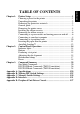
Chapter 1: Chapter 2: Chapter 3: Appendix A: Appendix B: Appendix C: Appendix D: Appendix E: . Printer Setup ............................................................................. 1 Choosing a place for the printer ................................................. 1 Unpacking the printer ................................................................. 2 Removing the protective materials ............................................. 2 General guide ...............................................
1 ENGLISH Chapter 1: Printer Setup This chapter contains important information on setting up your printer. Be sure to read this chapter carefully before using the printer for the first time.
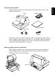
Unpacking the printer Check to make sure that the carton contains each of the items shown in the following illustration. Printer Ribbon cassette User’s Manual Ferrite core Fastener If anything is missing, contact the dealer where you bought the printer and ask them to supply the missing part. Note that it is a good idea to keep the original box and all the packing materials just in case you need to pack the printer up again and send it somewhere at a later date.
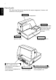
3 ENGLISH General guide The following illustrations describe the major components, buttons, and connectors of your printer. Printer cover Protects internal components. Control panel Three indicators show the printer status, and two switches provide control over printer functions. Power switch Turns printer power on and off. Peripheral unit connector cover Covers a modular jack for connection of a cash drawer or other peripheral. Do not connect a telephone line to this connector.
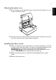
Removing the printer cover ❏ Push straight up on the ridged locations on the sides of the printer cover to remove it from the printer. ❏ To replace the cover, slide it back down into position. Gently press down on the cover until you hear it click securely into place. Installing the ribbon cassette ❏ Make sure that the printer’s paper release is activated (the paper is not held ❏ ❏ in place by the paper feed roller).
5 ENGLISH ❏ Remove the ribbon cassette from its packaging, and turn its knob in the direction indicated by the arrow to take up any slack in the ribbon. ❏ Holding the ribbon cassette so that the ribbon is facing down, install the cassette into the slip printer as shown in the illustration. ❏ Press gently but firmly on the cassette until it snaps securely into place. ❏ Rotate the knob on the cassette again to take up any slack. ❏ Replace the printer cover.
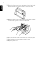
Removing the ribbon cassette Use the following procedure to remove the ribbon cassette from the slip printer when you want to replace it with a new one. ❏ Make sure that the printer is turned off and unplugged from its power ❏ ❏ outlet. Remove the printer cover. Grasping the ribbon cassette as shown, gently pull it away from the printing mechanism. ❏ Use the procedure under “Installing the ribbon cassette” on page 4 to install a new cassette.
7 ENGLISH ❏ Plug the other end of the power cord to a standard household wall outlet. ❏ Use the power switch on the left side of the printer to turn power on and off. Important! We recommend that you unplug the printer from the power outlet whenever you do not plan to use it for long periods. Because of this, you should locate the printer so that the power outlet it is plugged into is nearby and easy to access.
Connecting to your host computer The computer sends data to the printer through a cable to the printer’s interface (Serial Interface Connector Type: D-sub 25-pin or Parallel Interface Connector Type: 36-pin Centronics compatible). This printer does not come with a cable, so it is up to you to obtain one that suits your needs. Important! • The following instructions apply to the cable that is used with an IBMcompatible personal computer. Note that they do not apply to all types of computers and cables.
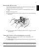
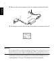
9 ENGLISH Pass the fastener through the ferrite core. 5 cm maximum Fastener Loop the fastener around the cable and lock it. Use scissors to cut off any excess. Pull and cut For a serial cable: ❏ Plug one end of the serial cable into the serial port of your computer, and the other end of the cable into the socket on the back of the printer. Secure both connectors in place with the screws that are provided.
Connecting to a peripheral unit You can connect a peripheral unit to the printer using a modular plug. The following describes how to install the ferrite core and make the actual connection. See “Modular plug” on page 137 for details about the type of modular plug that is required. Note that this printer does not come with a modular plug or wire, so it is up to you to obtain one that suits your needs.
11 ENGLISH Loop the fastener around the cable and lock it. Use scissors to cut off any excess. Pull and cut ❏ Plug one end of the modular cable into the modular jack of the peripheral. ❏ Remove the modular jack cover from the back of the printer and plug the other end of the modular cable into the jack of the printer. Inserting the paper into the printer Use only the specified type of paper for this printer. Do not use inappropriate types of paper, or it could cause malfunction or damage of the printer.
❏ Place a piece of the paper onto the printer’s document table and slide its right edge into the printer. Printing will be performed on the side of the paper that is facing up (the one you can see), starting from the top of the paper. Important! Do not use wrinkled or curled paper. In case of multiple paper, neatly align the sheets. Though paper can be inserted either from the front or side of the printer, front paper insertion may result in paper jams, depending on the condition of the paper.
13 ENGLISH ❏ Push the right edge of the paper into the printer until it stops. At that time, the PAPER OUT indicator will go out, and the printer mechanism will automatically align the paper for printing from the top. ❏ Send data from your host computer to be printed on the paper. ❏ After printing, press the RELEASE button to automatically release the paper.
Chapter 2: Control Panel Operations The control panel gives you some push-button control over the slip printer operation. It also includes indicator lights, which tell you the current status of the printer at a glance. FORWARD POWER RELEASE PAPER OUT REVERSE RELEASE Indicator lights The following table describes the meaning of indicator lights when it is on, off, or flashing.
15 ENGLISH Buttons The following table describes the function of the three control buttons of the control panel. Button Description FORWARD Feeds the slip paper forward, toward the back of the printer. One press feeds one line, holding down performs continuous feed. REVERSE Feeds the slip paper back, toward the front of the printer. One press feeds one line, holding down performs continuous feed.
This is caused when mechanical parts of the printer get out of alignment. This happens only rarely and you may never experience it at all throughout the life of the printer. If you do have problems, use the following procedure to correct it. ❏ Turn on the printer and insert a piece of paper. ❏ Turn off printer power. ❏ While holding down the control panel’s FORWARD and REVERSE buttons, turn the printer back on to enter the Dot Alignment Adjust Mode, which is indicator by a flashing POWER indicator flashes.
17 ENGLISH The dots alignment adjustment setting you selected is stored in printer memory and a pattern is printed using the selected setting followed by the message “Adjust Complete!” The printer ejects the paper after printing is complete. Note: You setting is not registered if you turn off printer power before pressing REVERSE to exit the Dot Alignment Adjust Mode. If a paper feed error occurs during this mode, the printer ejects the paper and this mode is cancelled.
Errors There are three types of errors: recoverable errors that require some action by you before they clear, non-recoverable errors that require servicing by an authorized service provider, and a data receive error. Errors are indicated by and audible buzzer and the indicators. Recoverable Errors Indicators Error Type Recovery POWER RELEASE PAPER OUT Paper jam Carriage motor lockup Correct the cause of the problem and then press RELEASE.
19 ENGLISH Paper Sensors The following paper sensors are available. ❏ TOF Sensor ❏ This top-of-form sensor detects the leading edge of the paper. When enabled, the TOF sensor detects when there is no paper present and stops printing. BOF Sensor This bottom-of-form sensor detects the trailing edge of the paper. When enabled, the BOF sensor detects when there is no paper present and printing is interrupted.
Chapter 3: Command Summary This printer supports two different command modes: the Star mode and the ESC/POS mode. The Star mode emulates previous Star printers. The ESC/POS mode emulates the Epson TM-295 or TM-290 slip printer. This chapter provides you with all of the commands supported by this printer. Important! Access the following URL for the latest version of this manual and for updates on supported commands: http://www.star-micronics.co.jp/service/ sp_sup_e.
21 ENGLISH Hexadecimal Codes Control Codes Function “W” n 1B 57 n Sets the magnification rate in character width “h” n 1B 68 n Sets the magnification rate in character height “–” “1” “–” <1> 1B 2D 31 1B 2D 01 Selects underlining “–” “0” “–” <0> 1B 2D 30 1B 2D 00 Cancels underlining “_” “1” “_” <1> 1B 5F 31 1B 5F 01 Selects upperlining “_” “0” “_” <0> 1B 5F 30 1B 5F 00 Cancels upperlining “4” 1B 34 Selects highlight pr
Print Position Control Hexadecimal Codes Control Codes Function 0A Line feed 0D Carriage Return “a” n 1B 61 n Feeds paper n lines 09 Horizontal tab “A” n 1B 41 n Defines n/72-inch line spacing “2” 1B 32 Sets n/72-inch line spacing “z” “0” “z” <0> 1B 7A 30 1B 7A 00 Sets line spacing to 1/12-inch “z” “1” “z” <1> 1B 7A 31 1B 7A 01 Sets line spacing to 1/6-inch “0” 1B 30 Sets line spacing to 1/8-inch “1” 1B 31 S
23 ENGLISH Dot Graphics Control Hexadecimal Codes Control Codes Function “K” n <0> m1 m2 ... 1B 4B n 00 m1 m2 ... 8 dot normal density graphics “L” n1 n2 m1 m2 ... 1B 4C n1 n2 m1 m2 ... 8 dot high density graphics Download Graphics Printing Hexadecimal Codes Control Codes Function “&” <0> n1 n2 .. 1B 26 00 n1 n2 ..
Slip Control Hexadecimal Codes Control Codes Function n 1B 0F n Setting slip sensor n 1B 0C n Slip function m n 1B 0B m n Sets the paper eject direction/length mn 1B 19 n m 0A 00 Sets the wait time until the automatic clamp is activated Page mode Hexadecimal Codes Control Codes Function “n” 1B 6E Selects page mode “!” 1B 21 Selects line mode “*” ... 1B 2A ...
25 ENGLISH Control Codes Hexadecimal Codes Function IB 06 01 Transmits automatic status “a” n IB IE 61 n Enables/disables automatic status “?” 1B 3F 0A 00 Resets printer hardware and produce a test print
ESC/POS Mode Commands (TM-295 emulation) The following table lists the TM-295 emulation commands that are supported by this printer.
27 ENGLISH Control Codes Hexadecimal Codes Function L 1B 4C Selects page mode R 1B 52 Selects international character set T 1B 54 Selects direction for page mode character printing U 1B 55 Selects print direction V 1B 56 Designates/cancels 90˚ character rotation W 1B 57 Sets print area for page mode printing a 1B 61 Aligns position c3 1B 63 33 Selects the paper-end sensor for sending the no-paper signal c4 1B 63 34 Selects
ESC/POS Mode Commands (TM-290 emulation) The following table lists the TM-290 emulation commands that are supported by this printer.
29 ENGLISH Control Codes Hexadecimal Codes Function R 1B 52 Selects international character set c3 1B 63 33 Selects the paper-end sensor for sending the no-paper signal c4 1B 63 34 Selects the paper-end sensor for stopping printing c5 1B 63 35 Enables/disables control panel switches d 1B 64 Prints or feeds n lines h 1B 68 Sets/Cancels reverse line feed j 1B 6A Selects character width in vertical printing mode q 1B 71 Release
TABLE DES MATIÈRES Configuration de l’imprimante............................................. 31 Emplacement de l’imprimante................................................. 31 Déballage de l’imprimante....................................................... 32 Retrait des matériaux de protection ......................................... 32 Description générale ................................................................ 33 Ouverture du capot...............................................................
31 Chapitre 1: Configuration de l’imprimante FRANÇAIS Ce chapitre vous fournira des informations importantes vous permettant de configurer votre imprimante. Veuillez lire attentivement ce chapitre avant d’utiliser l’imprimante pour la première fois.
32 Déballage de l’imprimante Contrôlez si la caisse contient bien tous les éléments illustrés ci-dessous. Cassette à ruban FRANÇAIS Imprimante Mode d’emploi Tore de ferrite Attache Si l’un des éléments mentionnés ci-dessus ne se trouve pas dans la caisse, adressez-vous au magasin où vous avez acheté l’imprimante et demandez que la pièce manquante vous soit fournie. Il est préférable de conserver la caisse d’origine ainsi que tous les emballages.
33 Description générale Les illustrations ci-dessous vous indiquent les principaux éléments, touches et connecteurs de l’imprimante. FRANÇAIS Capot Protège les organes internes de l’imprimante. Tableau de commande Ce tableau comprend deux interrupteurs de commande des fonctions et trois témoins indiquant le statut de l’imprimante. Interrupteur d’alimentation Cet interrupteur vous permet de mettre l’imprimante sous tension et hors tension.
34 Ouverture du capot ❏ Appuyez droit sur les sections cannelées des deux côtés du capot pour le FRANÇAIS détacher de l’imprimante. ❏ Pour remettre le capot en place, glissez-le en place et rabaissez-le. Appuyez délicatement sur le capot jusqu’à ce qu’il se verrouille dans un déclic. Installation de la cassette à ruban ❏ Assurez-vous que le levier de libération du papier est activé (le papier n’est ❏ ❏ pas maintenu en place par le rouleau d’alimentation du papier).
35 ❏ Déballez la cassette à ruban et tournez son bouton dans la direction indiquée par la flèche afin de tendre correctement le ruban. FRANÇAIS ❏ Saisissez la cassette à ruban de sorte que le ruban soit orienté vers le bas et installez-la dans l’imprimante à papier fort de la manière illustrée. ❏ Appuyez sans forcer sur la cassette de sorte qu’elle soit correctement ❏ ❏ verrouillée. Tournez à nouveau le bouton de la cassette afin de tendre le ruban. Remettez le capot de l’imprimante en place.
36 Retrait de la cassette à ruban Suivez les instructions ci-dessous lorsque vous souhaitez retirer la cassette à ruban afin de la remplacer. ❏ ❏ de la prise secteur. Retirez le capot de l’imprimante. Saisissez la cassette à ruban de la manière illustrée et retirez-la doucement du mécanisme d’impression. ❏ Installez la nouvelle cassette en suivant les instructions de la section “Installation de la cassette à ruban” à la page 34.
37 ❏ Raccordez l’autre bout du cordon d’alimentation à une prise secteur de tension appropriée. FRANÇAIS ❏ Mettez l’imprimante sous et hors tension à l’aide de l’interrupteur d’alimentation situé sur le côté gauche de l’imprimante. Attention! Nous vous recommandons de débrancher l’imprimante du secteur lorsque vous ne comptez pas l’utiliser pendant une période prolongée. Par ailleurs, veillez lors de l’installation à ce que la prise secteur alimentant l’imprimante soit proche et d’accès facile.
38 L’ordinateur communique les données à l’imprimante via le câble connecté à l’interface de l’imprimante (type de connecteur d’interface série : D-Sub à 25 broches ou type de connecteur d’interface parallèle : compatible Centronics à 36 broches). Ce câble n’est pas fourni avec l’imprimante. Vous devrez donc vous en procurer un. Attention! • Les instructions suivantes concernent le câble de connexion employé sur un ordinateur personnel compatible IBM.
39 Passez l’attache dans le tore de ferrite. 5 cm maximum FRANÇAIS Attache Passez l’attache autour du tore de ferrite et serrez-la. Coupez l’extrémité de l’attache à l’aide de ciseaux. Tirez et coupez Pour un câble série: ❏ Raccordez l’une des extrémités du câble en série au port d’interface en série de votre ordinateur, et l’autre extrémité dans la borne au dos de l’imprimante. Fixez les connecteurs à l’aide des vis fournies.
40 Vous pouvez raccorder un appareil périphérique à l’imprimante à l’aide d’une fiche modulaire. Nous expliquons ci-dessous comment installer le tore de ferrite et faire le raccordement proprement dit. Pour les détails sur le type de fiche modulaire à utiliser, reportez-vous à la page 137. Notez que le fil ou la fiche modulaires ne sont pas fournis avec l’imprimante. Vous devrez donc vous les procurer.
41 Passez l’attache autour du tore de ferrite et serrez-la. Coupez l’extrémité de l’attache à l’aide de ciseaux. Tirez et coupez FRANÇAIS ❏ Raccordez une extrémité du câble modulaire à la prise modulaire du ❏ périphérique. Retirez le cache de prise modulaire au dos de l’imprimante, et raccordez l’autre extrémité du câble modulaire dans la prise de l’imprimante. Introduction du papier dans l’imprimante Utilisez uniquement le type de papier recommandé pour cette imprimante.
42 ❏ Placez une feuille de papier dans le bac à papier de l’imprimante et faites Attention! Ne jamais utiliser de papier chiffonné ou recourbé. En cas d’utilisation de papiers multiples, veillez à bien aligner les différentes feuilles. Le papier peut être introduit par l’avant ou par le côté de l’imprimante. Néanmoins, l’introduction du papier par l’avant risque de provoquer un bourrage, en fonction de la condition du papier, et nous conseillons dès lors de toujours introduire le papier par le côté.
43 ❏ Poussez le bord droit du papier dans l’imprimante jusqu’à ce qu’il soit FRANÇAIS ❏ ❏ stoppé. A ce stade, le voyant d’absence de papier PAPER OUT s’éteint et le mécanisme de l’imprimante aligne automatiquement le papier pour commencer l’impression dans le haut de la feuille. Envoyez des données de votre ordinateur pour les imprimer sur le papier. Après l’impression, appuyez sur la touche RELEASE pour libérer automatiquement le papier.
44 Le panneau de commandes permet de contrôler le fonctionnement de l’imprimante de papier fort par boutons poussoir. Il contient également des témoins lumineux qui vous indiquent l’état de l’imprimante en un simple coup d’œil. FORWARD POWER RELEASE PAPER OUT REVERSE RELEASE Témoins lumineux Le tableau ci-dessous vous explique l’état de l’imprimante pour chaque témoin allumé, éteint ou clignotant.
45 Touches Le tableau ci-dessous vous explique la fonction des trois touches du tableau de commande. FRANÇAIS Touche Description FORWARD Alimente le papier fort vers l’avant, vers le dos de l’imprimante. Une pression fait avancer le papier d’une ligne, une pression continue produit une avance continue. REVERSE Alimente le papier fort vers l’arrière, vers l’avant de l’imprimante. Une pression fait avancer le papier d’une ligne, une pression continue produit une avance continue.
46 ❏ Mettez l’imprimante sous tension et introduisez un morceau de papier. ❏ Mettez l’imprimante hors tension. ❏ Tout en maintenant les touches FORWARD et REVERSE du tableau de commande enfoncées, remettez l’imprimante sous tension afin d’activer le mode de réglage d’alignement des points, qui est signalé par le clignotement du témoin POWER.
47 Le réglage d’alignement des points que vous avez sélectionné est sauvegardé dans la mémoire, et l’imprimante imprime une série de lignes graduées correspondant à l’état d’impression sélectionné, suivie du message “Adjust Completed!”, vous indiquant que le réglage est terminé. L’imprimante éjecte ensuite le morceau de papier fort.
48 Vous pouvez rencontrer trois types d’erreur : les erreurs corrigibles, que vous pouvez corriger en effectuant certaines opérations, les erreurs non corrigibles, dont la correction nécessite l’intervention d’un revendeur agréé, et l’erreur de réception des données. Les erreurs sont signalées par un avertisseur sonore et par des témoins.
49 Capteurs de papier Les capteurs de papier suivants sont prévus. ❏ Capteur TOF FRANÇAIS ❏ Ce capteur haut-de-page détecte le bord d’attaque du papier. Lorsqu’il est validé, le capteur TOF détecte l’absence de papier et il arrête l’impression. Capteur BOF Ce capteur bas-de-page détecte le bord arrière du papier. Lorsqu’il est validé, le capteur BOF détecte l’absence de papier et l’impression est interrompue.
50 Chapitre 3: Résumé des commandes Le mode Star émule les imprimantes Star précédentes. Le mode ESC/POS émule l'imprimante de bordereaux TM-295 ou TM-290 Epson. Ce chapitre donne la liste de toutes les commandes supportées par l’imprimante. Attention! Pour obtenir la dernière version de ce manuel et pour les mises à jour des commandes supportées, consultez l’adresse URL suivante : http://www.starmicronics.co.jp/service/sp_sup_e.htm.
51 Code de contrôle “W” n Code hexadécimal Fonction 1B 57 n Règle l’indice d’amplification pour la largeur des caractères 1B 68 n Règle l’indice d’amplification pour la hauteur des caractères “–” “1” “–” <1> 1B 2D 31 1B 2D 01 Validation du soulignement “–” “0” “–” <0> 1B 2D 30 1B 2D 00 Invalidation du soulignement “_” “1” “_” <1> 1B 5F 31 1B 5F 01 Validation du surlignement “_” “0” “_” <0> 1B 5F 30 1B 5F00 Invalidation du surlignement
52 Commandes de position d’impression Code hexadécimal Fonction 0A Avance d’une ligne 0D Retour chariot “a” n 1B 61 n Avance du papier de n lignes 09 Tabulation horizontale “A” n 1B 41 n Sélection d’un interligne de n/72èmes de pouce “2” 1B 32 Validation d’un interligne de n/72èmes de pouce “z” “0” “z” <0> 1B 7A 30 1B 7A 00 Validation d’un interligne de 1/12ème de pouce “z” “1” “z” <1> 1B 7A 31 1B 7A 01 Validation d’un interli
53 Commandes de graphiques en points FRANÇAIS Code de contrôle Code hexadécimal Fonction “K” n <0> m1 m2 ... 1B 4B n 00 m1 m2... “L” n1 n2 m1 m2... 1B 4C n1 n2 m1 m2... Impression de graphiques à haute densité Impression de graphiques à densité normale Impression de graphiques téléchargés Code de contrôle Code hexadécimal Fonction “&” <0> n1 n2 .. 1B 26 00 n1 n2 ..
54 Mode de page Code hexadécimal Fonction “n” 1B 6E Sélection du mode page “!” 1B 21 Sélection du mode ligne “*” ... 1B 2A ...
55 Commandes du mode ESC/POS (Émulation de la TM-295) Le tableau ci-dessous donne la liste des commandes d'émulation de la TM-295 qui sont supportées par l'imprimante.
56 Code hexadécimal Fonction L 1B 4C Sélection du mode page R 1B 52 Sélection du jeu de caractères internationaux T 1B 54 Sélection du sens d’impression pour l’impression des caractères en mode page U 1B 55 Sélection du sens d’impression V 1B 56 Désignation/annulation de la rotation de 90˚ des caractères W 1B 57 Sélection de la zone d’impression pour l’impression en mode page a 1B 61 Alignement de la position c3 1B 63 33 Commande au c
57 Commandes du mode ESC/POS (Émulation de la TM-290) Le tableau ci-dessous donne la liste des commandes d'émulation de la TM-290 qui sont supportées par l'imprimante.
58 Code hexadécimal Fonction R 1B 52 Sélection du jeu de caractères internationaux c3 1B 63 33 Commande au capteur de papier d’envoyer le signal “papier épuisé”. c4 1B 63 34 Commande au capteur de papier d’interrompre l’impression.
INHALTSVERZEICHNIS Drucker-Einrichtung ................................................................ 61 Wahl eines Aufstellungsorts für den Drucker............................. 61 Auspacken des Druckers............................................................. 62 Entfernen der Schutzmaterialien................................................. 62 Allgemeine Anleitung................................................................. 63 Abnehmen der Druckerabdeckung .......................................
61 Kapitel 1: Drucker-Einrichtung Dieses Kapitel enthält wichtige Informationen zur Vorbereitung Ihres Druckers. Bitte dieses Kapitel sorgfältig durchlesen, bevor Sie den Drucker zum ersten Mal in Betrieb nehmen.
62 Auspacken des Druckers Überprüfen Sie den Kartoninhalt, und vergewissern Sie sich, daß alle unten abgebildeten Teile vorhanden sind. Farbbandkassette Bedienungsanleitung Ferritkern Kabelbinder Falls Teile fehlen, wenden Sie sich zwecks Nachlieferung bitte an den Fachhandel, bei dem das Gerät gekauft wurde. Im Hinblick auf einen eventuellen zukünftigen Transport des Druckers empfiehlt es sich, den Lieferkarton und das gesamte Verpackungsmaterial aufzubewahren.
63 Allgemeine Anleitung Die folgenden Abbildungen zeigen die Hauptbauteile des Druckers. Druckerabdeckung Schützt interne Bauteile. Bedienfeld Drei Anzeigen zeigen den Druckerzustand, und zwei Schalter erlauben Steuerung von Druckerfunktionen. DEUTSCH Netzschalter Zum Ein- und Ausschalten des Druckers. Dokumentenauflage Stützt das Quittungspapier, das in den Quittungsdrucker eingeschoben wird.
64 Abnehmen der Druckerabdeckung ❏ Die geriffelten Teile an den Druckerseiten gerade nach oben drücken, um DEUTSCH die Abdeckung abzunehmen. ❏ Zum Schließen die Abdeckung wieder nach unten aufsetzen. Vorsichtig aufdrücken, bis sie hörbar einrastet. Einsetzen der Farbbandkassette ❏ Stellen Sie sicher, daß die Papierfreigabe des Druckers aktiviert ist (das ❏ ❏ Papier wird nicht von der Papier-Zufuhrrolle festgehalten).
65 ❏ Die Farbbandkassette aus der Verpackung nehmen, und den Knopf auf der Farbbandkassette im Uhrzeigersinn drehen, um eventuell vorhandene Bandschlaufen aufzuwickeln. DEUTSCH ❏ Die Farbbandkassette so halten, daß das Farbband nach unten weist und die Kassette in den Drucker einsetzen, wie in der Abbildung gezeigt. ❏ Die Farbbandkassette sanft aber fest herunterdrücken, bis sie hörbar ❏ ❏ einrastet. Den Farbband-Spannknopf auf der Kassette noch einmal drehen, um das Band zu straffen.
66 Entnehmen der Farbbandkassette Folgendermaßen verfahren, um die Farbbandkassette zum Austausch aus dem Drucker zu nehmen. ❏ Sicherstellen, daß der Drucker ausgeschaltet und von der DEUTSCH ❏ ❏ Betriebsstromversorgung getrennt ist. Die Druckerabdeckung abnehmen. Die Farbbandkassette wie in der Abbildung gezeigt greifen und vorsichtig aus dem Druckmechanismus ziehen. ❏ Die unter “Einsetzen der Farbbandkassette” auf Seite 64 beschriebenen Schritte ausführen.
67 ❏ Den anderen Stecker des Netzkabels an eine Netzsteckdose anschließen. DEUTSCH ❏ Den Netzschalter an der linken Seite des Druckers zum Ein- und Ausschalten verwenden. Wichtig! Wir empfehlen, den Netzstecker aus der Steckdose zu ziehen, wenn der Drucker längere Zeit lang nicht benutzt werden soll. Der Drucker sollte vorzugsweise an einem Platz aufgestellt werden, der leichten Zugang zur Netzsteckdose gewährt.
68 Anschließen an den Hostcomputer Wichtig! • Die folgende Anleitung bezieht sich auf das von IBM-kompatiblen PCs benutzte Kabel und ist deshalb nicht auf alle Computer und Kabel zutreffend. Wenden Sie sich bitte an Ihren Fachhändler, falls Sie Fragen hinsichtlich des für Ihren Computer geeigneten Kabeltyps haben. • Vor dem Anschließen der Kabel sicherstellen, daß der Drucker ausgeschaltet und vom Netz getrennt ist.
69 Führen Sie den Kabelbinder durch den Ferritkern. Maximum 5 cm Kabelbinder DEUTSCH Führen Sie den Kabelbinder um das Kabel und sperren Sie ihn. Schneiden Sie überschüssiges Band mit einer Schere ab. Ziehen und abschneiden Für ein serielles Schnittstellenkabel: ❏ Ein Ende des Kabels an den seriellen Anschluß des Computers anschließen und das andere Ende an die Buchse an der Rückseite des Druckers an. Wenn die Stecker durch Schrauben gesichert werden können, diese festziehen.
70 Anschluß an ein Peripheriegerät Es kann ein Peripheriegerät an den Drucker mit einem Modularstecker angeschlossen werden. Im folgenden wird beschrieben, wie der Ferritkern angebracht und die Verbindung hergestellt wird. Siehe “Modularstecker” auf Seite 137 für den Typ von Modularstecker, der dazu erforderlich ist. Beachten Sie, daß der Drucker nicht mit einem Modularstecker oder Kabel ausgestattet ist. Diese Teile müssen vom Anwender besorgt werden.
71 Das Befestigungsband um das Kabel wickeln und sperren. Schneiden Sie überschüssiges Band mit einer Schere ab. Ziehen und abschneiden ❏ Einen Stecker des Modularkabels in die Modularbuchse am Peripheriegerät DEUTSCH ❏ stecken. Die Modularbuchsenabdeckung von der Rückseite des Druckers abnehmen, und den anderen Stecker des Modularkabels in die Modularbuchse am Drucker stecken. Papier in den Drucker einlegen Benutzen Sie nur Papierarten, die für diesen Drucker speziell angegeben sind.
72 ❏ Legen Sie ein Blatt Papier auf den Dokumententisch des Druckers und schieben Sie die rechte Ecke in den Drucker. Der Ausdruck erfolgt auf der Seite, die nach oben zeigt (die Seite, die Sie sehen können) und beginnt am oberen Rand des Blattes. Wichtig! Das Papier kann von vorne oder von der Seite in den Drucker eingelegt werden. Es kann aber beim Einlegen von vorne, in Abhängigkeit vom Zustand des Papiers, ein Papierstau verursacht werden.
73 ❏ Schieben Sie die rechte Ecke des Blattes in den Drucker, bis Sie einen Widerstand spüren. Zu diesem Zeitpunkt wird die Anzeige PAPER OUT ausgehen und der Druckermechanismus zieht das Blatt automatisch ein und richtet es an der Druckstartposition aus. ❏ Senden Sie die Druckdaten, die auf dieses Blatt gedruckt werden sollen, ❏ von ihrem Computer zum Drucker. Drücken Sie nach erfolgtem Ausdruck auf die Taste RELEASE und das Blatt wird automatisch freigegeben.
74 Kapitel 2: Bedienfeld Das Bedienungsfeld enthält einige Tasten, mit deren Hilfe Sie den Drucker bedienen künnen. Es enthält auch einige LED-Anzeigen, die Sie über den aktuellen Status des Druckers informieren. FORWARD POWER RELEASE REVERSE DEUTSCH PAPER OUT RELEASE Anzeigeleuchten Die folgende Tabelle stellt die Bedeutung des Leuchtens, Nichtleuchtens oder Blinkens der Anzeigeleuchten dar.
75 Tasten Die folgende Tabelle stellt die Funktion der drei Steuertasten am Bedienfeld dar. Taste Beschreibung DEUTSCH FORWARD Drücken, um das Quittungspapier zur Rückseite des Druckers zuzuführen. Ein Tastendruck schiebt um eine Zeile vor, Gedrückthalten schiebt kontinuierlich vor. REVERSE Drücken , um das Quittungspapier zur Vorderseite des Druckers zurückzuführen. Ein Tastendruck schiebt um eine Zeile vor, Gedrückthalten schiebt kontinuierlich vor.
76 Der Grund dafür ist, daß mechanische Teile des Druckers gegeneinander verschoben werden. Dies geschieht nur selten, und die meisten Anwender werden während der Lebensdauer des Druckers damit nicht konfrontiert werden. Falls aber dieses Problem auftritt, kann es auf folgende Weise behoben werden. und den Drucker erneut einschalten, um auf Punktausrichtung zu schalten. Die Betriebsart wird durch das Blinken der POWER-Anzeige angezeigt.
77 Die Einstellungen für die Punktausrichtung werden im Druckerspeicher gespeichert, und ein Muster wird mit der gewählten Einstellung ausgedruckt, gefolgt von der Meldung “Adjust Complete!”. Der Drucker gibt das Papier nach dem Druckvorgang aus. DEUTSCH Hinweis: Wenn der Drucker ausgeschaltet wird, ohne die Taste REVERSE zum Verlassen des Punkteinstellmodus zu drücken, werden die Einstellungen nicht gespeichert.
78 Fehler Es gibt drei Typen von Fehlern: behebbare Fehler, die zum Beheben eine Maßnahme von Seiten des Anwenders erfordern, und nicht behebbare Fehler, die Wartungsmaßnahmen durch den Kundendienst erfordern, und Datenempfangsfehler. Die Fehlertypen werden durch ein Tonsignal und die Anzeigen dargestellt. Anzeigen Fehlertyp Behebung POWER RELEASE PAPER OUT Papierstau Wagenmotor-Blockierung Die Ursache des Problems beheben, und dann RELEASE drücken.
79 Papiersensoren Die folgenden Papiersensoren stehen zur Verfügung. ❏ TOF-Sensor ❏ Dieser Vorderkantensensor (“top of form”) erkennt die Papiervorderkante. Wenn er aktiviert ist, erkennt der TOF-Sensor, daß kein Papier vorhanden ist und stoppt den Druckvorgang. BOF-Sensor Dieser Hinterkantensensor (“bottom of form”) erkennt die Hinterkante des Papiers. Wenn er aktiviert ist, erkennt der BOF-Sensor, daß kein Papier vorhanden ist und unterbricht den Druckvorgang.
80 Kapitel 3: Zusammenfassung der Befehle Dieser Drucker unterstützt zwei verschiedene Befehlsmodi: den Star-Modus und den ESC/POS-Modus, Der Star-Modus emuliert den Befehlssatz der Star-Drucker. Der Modus ESC/ POS emuliert den Epson TM295 oder TM-290 Quittungsdrucker. Wichtig! Die neueste Version dieser Anleitung und Aktualisierungen der unterstützten Befehlssätze sind im Internet bei der folgenden URL erhältlich: http:// www.star-micronics.co.jp/service/sp_sup_e.
81 Steuerbefehle Sedezimal-Codes Funktion DEUTSCH “W” n 1B 57 n Druck mit doppelter Zeichenbreite ein- bzw. ausschalten “h” n 1B 68 n Druck mit doppelter Zeichenhöhe ein- bzw.
82 Ändern der Druckposition Sedezimal-Codes Funktion 0A Zeilenvorschub 0D Wagenrücklauf “a” n 1B 61 n Papiervorschub n Zeilen einstellen 09 Nächste horizontale Tabulatorposition “A” n 1B 41 n Zeilenabstand n/72 Zoll definieren “2” 1B 32 Zeilenabstand von n/72 Zoll ausführen “z” “0” “z” <0> 1B 7A 30 1B 7A 00 Zeilenabstand 1/12 Zoll einstellen “z” “1” “z” <1> 1B 7A 31 1B 7A 01 Zeilenabstand 1/6 Zoll einstellen “0” 1B 30
83 Druck von Rastergrafiken Steuerbefehle Sedezimal-Codes Funktion “K” n <0> m1 m2 ... 1B 4B n 00 m1 m2 ... Grafikdruck in normaler Auflösung “L” n1 n2 m1 m2 ... 1B 4C n1 n2 m1 m2 ... Grafikdruck in hoher Auflösung Druck von heruntergeladenen Zeichen DEUTSCH Steuerbefehle Sedezimal-Codes Funktion “&” <0> n1 n2 .. 1B 26 00 n1 n2 ..
84 Befehle für Seitenmodus Sedezimal-Codes Funktion “n” 1B 6E Seitenmodus wählen “!” 1B 21 Zeilenmodus wählen “*” ... 1B 2A ...
85 Befehle des ESC/POS-Modus (TM-295 Emulation) Die folgende Tabelle führt die TM-295 Emulationsbefehle aus, die von diesem Drucker unterstützt werden.
86 Sedezimal-Codes Funktion L 1B 4C Seitenmodus wählen R 1B 52 Internationalen Zeichensatz wählen T 1B 54 Richtung für Seitendruck-Zeichendruck wählen U 1B 55 Wahl der Druckrichtung V 1B 56 90˚ Zeichendrehung EIN/AUS W 1B 57 Druckbereich für Seitenmodus-Druck einstellen a 1B 61 Position ausrichten c3 1B 63 33 Papierende-Sensor für Papierende-Signal einstellenn c4 1B 63 34 Papierende-Sensor für Druckabbruch einstellen c
87 Befehle des ESC/POS-Modus (TM-290 Emulation) Die folgende Tabelle führt die TM-290 Emulationsbefehle aus, die von diesem Drucker unterstützt werden.
88 Sedezimal-Codes Funktion R 1B 52 Internationalen Zeichensatz wählen c3 1B 63 33 Papierende-Sensor für Papierende-Signal einstellenn c4 1B 63 34 Papierende-Sensor für Druckabbruch einstellen c5 1B 63 35 Bedienfeldschalter aktivieren/deaktivieren d 1B 64 n Zeilen drucken oder vorschieben h 1B 68 Aktiviert/Deaktiviert den Rückwärts-Zeilenvorschub j 1B 6A Wählt die Zeichenbreite im vertikalen Druckmodus q 1B 71 Freigeben t 1B 7
INDICE Preparativi.............................................................................. 91 Scelta di un luogo per la stampante ......................................... 91 Disimballaggio della stampante............................................... 92 Rimozione del materiale protettivo.......................................... 92 Guida generale ......................................................................... 93 Rimozione del coperchio stampante ........................................
91 Capitolo 1: Preparativi Questo capitolo contiene informazioni importanti su come preparare la stampante. Assicurarsi di leggere attentamente questo capitolo prima di usare la stampante per la prima volta.
92 Disimballaggio della stampante Controllare che lo scatolone contenga tutti gli elementi indicati nella seguente illustrazione. Stampante Cassetta del nastro Manuale di istruzioni Fascetta di fissaggio Se dovesse mancare qualcosa, contattare il concessionario da cui si è acquistata la stampante e richiedere la parte mancante. Notare che è consigliabile conservare lo scatolone originale e tutti i materiali di imballaggio in caso si debba reimballare e spedire la stampante in futuro.
93 Guida generale Le seguenti illustrazioni descrivono le parti principali, i tasti e i connettori della stampante. Coperchio della stampante Protegge i componenti interni. ITALIANO Pannello comandi Tre spie indicano lo stato della stampante e due interruttori permettono di controllare le funzioni della stampante. Interruttore di alimentazione Per accendere e spegnere la stampante.
94 Rimozione del coperchio stampante ❏ Spingere direttamente verso l’alto sulle zigrinature sui lati del coperchio ❏ Per rimettere il coperchio, abbassarlo in posizione. Premere leggermente sul coperchio fino a sentire che scatta in posizione. Inserimento della cassetta del nastro ❏ Assicurarsi che il meccanismo di rilascio carta della stampante sia attivato ❏ ❏ (la carta non viene mantenuta in posizione dal rullo di avanzamento carta).
95 ❏ Rimuovere la cassetta del nastro dalla confezione e girare la sua manopola nella direzione indicata dalla freccia per eliminare eventuali allentamenti del nastro. ITALIANO ❏ Tenendo la cassetta del nastro con il nastro rivolto verso il basso, inserire la cassetta nella stampante di moduli come indicato nell’illustrazione. ❏ Premere delicatamente ma con fermezza fino a che la cassetta scatta ❏ ❏ saldamente in posizione. Girare di nuovo la manopola della cassetta per eliminare allentamenti.
96 Rimozione della cassetta del nastro Usare il seguente procedimento per rimuovere la cassetta del nastro dalla stampante di moduli quando si desidera sostituirla con un’altra nuova. ❏ Assicurarsi che la stampante sia spenta e scollegata dalla presa di corrente. ❏ Rimuovere il coperchio della stampante. ❏ Afferrare la cassetta del nastro come illustrato e tirarla via dolcemente dal ITALIANO meccanismo di stampa.
97 ❏ Collegare l’altro capo del cavo di alimentazione ad una presa di corrente normale. ❏ Usare l’interruttore di alimentazione sul lato sinistro della stampante per accendere e spegnere. ITALIANO Importante! Consigliamo di scollegare la stampante dalla presa di corrente quando si prevede di non usarla per un lungo periodo. Per questo motivo, la stampante deve essere collocata in modo che la presa di corrente sia vicina e facilmente accessibile.
98 Collegamento al computer ospite Il computer invia dati alla stampante tramite un cavo collegato all’interfaccia della stampante (tipo connettore interfaccia seriale: D-sub a 25 terminali o tipo connettore interfaccia parallela: compatibile Centronics a 36 terminali). Questa stampante non è dotata di cavo, che deve essere acquistato a seconda delle esigenze di impiego. ❏ Fissare l’anello di ferrite più grande al cavo come mostrato nell’illustrazione qui sotto.
99 Far passare la fascetta di fissaggio attraverso l’anello di ferrite. 5 cm massimo Fascetta di fissaggio Avvolgere la fascetta intorno al cavo e fissarla. Usare delle forbici per tagliare la parte in eccesso. ITALIANO Tirare e tagliare Per un cavo seriale: ❏ Collegare un capo del cavo seriale alla porta seriale del computer e l’altro capo alla presa sul retro della stampante. Fissare entrambi i connettori in posizione con le viti in dotazione.
100 Collegamento ad un’unità periferica Si può collegare un’unità periferica alla stampante usando una spina modulare. Di seguito descriviamo come installare l’anello di ferrite ed eseguire il collegamento. Vedere “Modulare necessario” a pagina 137 per dettagli sul tipo di spina modulare necessario. Notare che la stampante non è dotata di spina o filo modulare, che devono essere acquistati in base alle esigenze di impiego.
101 Avvolgere la fascetta intorno al cavo e fissarla. Usare delle forbici per tagliare la parte in eccesso. Tirare e tagliare ❏ Collegare un capo del cavo modulare alla presa modulare della periferica. ❏ Rimuovere il coperchio presa modulare dal retro della stampante e collegare l’altro capo del cavo modulare alla presa sulla stampante. ITALIANO Inserimento della carta nella stampante Usare esclusivamente carta del tipo specificato per questa stampante.
102 ❏ Collocare un foglio di carta sul ripiano documenti della stampante ed inserire il bordo destro nella stampante. La stampa verrà eseguita sul lato della carta rivolto verso l’alto (quello visibile), partendo dal margine superiore del foglio. Importante! Non usare carta sgualcita o arricciata. In caso di utilizzo di carta a più copie, allineare esattamente i fogli.
103 ❏ Spingere il bordo destro della carta nella stampante fino al suo arresto. A questo punto, la spia PAPER OUT si spegnerà, e il meccanismo della stampante allineerà automaticamente la carta per la stampa partendo dal margine superiore. ❏ Inviare i dati da stampare sulla carta dal computer principale. ❏ Terminata la stampa, premere il tasto RELEASE per rilasciare automaticamente la carta.
104 Chapter 2: Operazioni con il pannello comandi Il pannello di controllo consente di controllare il funzionamento della stampante tipo slip mediante l’uso di tasti. Esso comprende inoltre alcune spie luminose che consentono all’operatore di conoscere con una rapida occhiata lo stato operativo della stampante. FORWARD POWER RELEASE PAPER OUT REVERSE ITALIANO RELEASE Spie di indicazione La seguente tabella descrive il significato delle spie di indicazione quando sono accese, spente o lampeggianti.
105 Tasti La seguente tabella descrive le funzioni dei tre tasti di controllo del pannello comandi. Tasto Descrizione FORWARD Fa avanzare il modulo di carta in avanti, verso il retro della stampante. Una pressione del tasto fa avanzare la carta di una riga, tenendo il tasto premuto viene eseguito l’avanzamento continuo. REVERSE Fa retrocedere il modulo di carta, verso il davanti della stampante.
106 Questo è causato da una perdita di allineamento delle parti meccaniche della stampante. Questo succede solo raramente e può non verificarsi mai durante l’uso della stampante. Se si hanno problemi, usare il seguente procedimento per correggerli. ❏ Accendere la stampante ed inserire un foglio di carta. ❏ Spegnere la stampante.
107 L’impostazione di allineamento punti selezionata viene conservata nella memoria della stampante e viene stampato uno schema che impiega l’impostazione selezionata seguito dal messaggio “Adjust complete!”. La stampante espelle la carta una volta completata la stampa. Nota: ITALIANO Le impostazioni non sono registrate se si spegne la stampante prima di premere REVERSE per uscire dal modo di regolazione allineamento punti.
108 Errori Esistono tre tipi di errori: errori recuperabili, che richiedono un’azione da parte dell’operatore prima di essere risolti; errori non ricuperabili, che richiedono assistenza da parte di tecnici autorizzati; ed errori di ricezione dati. Gli errori sono indicati da un segnale acustico e dalle spie di indicazione.
109 Sensori carta Sono disponibili i seguenti sensori ❏ Sensore TOF ❏ Questo sensore di parte superiore modulo individua il bordo anteriore della carta. Quando è abilitato, il sensore TOF individua l’assenza di carta e ferma la stampa. Sensore BOF Questo sensore di parte inferiore modulo individua il bordo posteriore della carta. Quando è abilitato, il sensore BOF individua l’assenza di carta e ferma la stampa.
110 Chapter 3: Sommario dei comandi Questa stampante supporta due diversi modi di comando: il modo Star e il modo ESC/POS. Il modo Star emula i modelli precedenti di stampanti Star. Il modo ESC/POS emula la stampante slip Epson TM-295 o TM-290. Questo capitolo fornisce tutti i comandi supportati dalla stampante. Comandi del modo Star Le seguenti tabelle mostrano i comandi del modo Star supportati da questa stampante.
111 Codici di controllo Codici esadecimali Funzione ITALIANO “W” n 1B 57 n Imposta il fattore d’ingrandimento per la larghezza del carattere “h” n 1B 68 n Imposta il fattore d’ingrandimento per l’altezza del carattere “–” “1” “–” <1> 1B 2D 31 1B 2D 01 Seleziona la sottolineatura “–” “0” “–” <0> 1B 2D 30 1B 2D 00 Annulla la sottolineatura “_” “1” “_” <1> 1B 5F 31 1B 5F 01 Seleziona la sopralineatura “_” “0” “_” <0> 1B 5F 30 1B 5
112 Controllo della posizione di stampa Codici esadecimali Funzione 0A Avanzamento riga 0D Ritorno carrello “a” n 1B 61 n Avanzamento carta di n righe 09 Tabulazione orizzontale “A” n 1B 41 n Definisce l’interlinea a n/72 di pollice “2” 1B 32 Imposta l’interlinea a n/72 di pollice “z” “0” “z” <0> 1B 7A 30 1B 7A 00 Imposta l’interlinea a 1/12 di pollice “z” “1” “z” <1> 1B 7A 31 1B 7A 01 Imposta l’interlinea a 1/6 di pollice
113 Controllo grafica a punti Codici di controllo Codici esadecimali Funzione “K” n <0> m1 m2 ... 1B 4B n 00 m1 m2 ... Stampa la grafica a densità normale “L” n1 n2 m1 m2 ... 1B 4C n1 n2 m1 m2 ... Stampa la grafica ad alta densità Stampa di grafica scaricata Codici di controllo Codici esadecimali Funzione ITALIANO “&” <0> n1 n2 .. 1B 26 00 n1 n2 ..
114 Controllo moduli Codici di controllo Codici esadecimali Funzione n 1B 0F n Impostazione sensore dello slip n 1B 0C n Funzione di slip m n 1B 0B m n Imposta la direzione/lunghezza dell’espulsione della carta mn 1B 19 n m 0A 00 Imposta il tempo di attesa per l’attivazione del blocco automatico Modo di pagina Codici esadecimali Funzione “n” 1B 6E Seleziona il modo pagina “!” 1B 21 Seleziona il modo riga “*” ...
115 Codici di controllo Codici esadecimali Funzione “a” n IB IE 61 n Abilita/disabilita lo stato automatico “?” 1B 3F 0A 00 Ripristino hardware della stampante ed esecuzione di una stampa di prova ITALIANO
116 Comandi del modo ESC/POS (emulazione TM-295) La seguente tabella elenca i comandi di emulazione TM-295 supportati da questa stampante.
117 Codici di controllo Codici esadecimali Funzione ITALIANO L 1B 4C Seleziona il modo pagina R 1B 52 Selezione il gruppo caratteri internazionali T 1B 54 Seleziona la direzione per la stampa caratteri del modo pagina U 1B 55 Seleziona la direzione di stampa V 1B 56 Attiva/disattiva la rotazione di 90˚ del carattere W 1B 57 Seleziona l’area di stampa per la stampa del modo pagina a 1B 61 Allinea la posizione di stampa c3 1B 63 33 Sl
118 Comandi del modo ESC/POS (emulazione TM-290) La seguente tabella elenca i comandi di emulazione TM-290 supportati da questa stampante.
119 Codici di controllo Codici esadecimali Funzione ITALIANO R 1B 52 Selezione il gruppo caratteri internazionali c3 1B 63 33 Slezionare il sensore carta per l’invio del segnale di assenza c4 1B 63 34 Selezionare il sensore di fine carta per l’arresto c5 1B 63 35 Abilita/disabilita gli interruttori del panello comandi d 1B 64 Stampa o fa avanzare di n righe h 1B 68 Imposta/disattiva l'avanzamento riga inverso j 1B 6A Seleziona la larghezza d
120 Appendix A: Specifications General Specifications Printing System Number of Head Pins Printing Speed Number of Print Columns Dot spacing Paper Width Sensors Command Modes Interface Serial impact dot-matrix 9 wires 3.1 lines/sec maximum 42 Horizontal: 0.30mm Vertical: 0.
121 Dimensions and Weight Dimensions Weight 180 (W) × 190 (D) × 138 (H) mm / 7.09″ × 7.48″ × 5.43″ 2.1 kg / 4.6 lbs. 180 mm (7.09″) 138 mm (5.43″) APPENDIX 190 mm (7.
122 80 to 182mm / 3.15″ to 7.17″ Paper Length Copies Paper Thickness 80 to 257mm / 3.15″ to 10.8″ Original + 2 1-ply: 0.09 to 0.2mm / 0.0035″ to 0.0079″ Duplicates 0.12 mm (minimum for 2-ply forms) to 0.25 mm/0.0047″ to 0.0098″ 1.5mm maximum/15 lines (between top sheet and bottom sheet) Top or left Copy Offset Binding Print Area Distance from first printed line (Head #1) to top of form (form stopper): 28.
123 Print Position 8 mm No holes in this area Paper feed direction Do not use paper with perforations within the shaded area. Perforations may cause the paper sensor to erroneously report an out of paper condition. Paper Feed Drive Pitch Speed (while printing) Speed (while ejecting) Stepping motor Star Mode: Adjustable in 1/144″ units ESC/POS Mode: Adjustable in n/60″ units (approximate) 3.5″ per second 4.
124 Power Supply Specifications Power Supply Operating (approximate averages) Stand-by (approximate averages) PS48-24A, switching type 90 to 264V AC, 50/60Hz 24V DC ± 5%, 2.0A 3-pin POWER JACK TCP 8927 (Hoshiden brand or equivalent.) Conditions: 24V, excluding external equipment driving Continuous ASCII printing + paper feed: 0.6A Solid block printing + paper feed: 1.0A Solid block printing: 1.9A Peak (solid printing): 3.1A Paper release deactivated: 0.24 A Paper release activated: 0.
125 Appendix B: Making DIP Switch Settings The printer’s DIP switches let you specify communications parameters, receive buffer size, and emulation. This Appendix explains the settings you can make and tells you how to actually change DIP switch settings. Accessing the DIP switches The DIP switches are located inside the printer, underneath the document table. Use the following procedure to remove the document table so you can operate the DIP switches.
126 ON OFF It is not necessary to remove the document table completely, just move it enough so you can get at the DIP switches inside. ON (For Serial Interface) 1 2 3 4 5 6 7 8 1 2 3 4 5 6 7 8 9 10 ON (For Parallel Interface) OFF Note: If the document table seems to be getting caught on the rollers, it means that you are not pressing down at point (a) enough. Pressing at point (a) should separate the rollers to the document table can slide freely.
127 Available DIP switch settings (Serial Interface) The following table shows all the possible settings for the DIP switch. The factory default settings are ON for switches 1 through 7 and OFF for switches 8 through 10. Switch Parameter ON OFF 1 Baud Rate See table below. 2 3 Data Length 8 bits 7 bits 4 Parity Check Disabled Enabled 5 Parity Odd Even 6 Handshake DTR/DSR XON/XOFF 7 Command Emulation See table below.
128 Available DIP switch settings (Parallel Interface) The following table shows all the possible settings for the DIP switch. The factory default settings are ON for switches 1 through 7 and OFF for switch 8.
129 *2 A reset can be performed with pin 31 on the interface by setting DIP switch 1 to ON (the factory default setting). In addition, when a reset can be performed with pin 31, setting DIP switch 2 to OFF sets up the unit to perform a reset when pin 31 and pin 36 are “LOW”. *3 Disable if using #36 pin (nSelectIn/1284 Active) interface for functions other than IEEE1284. *4 Never set switch 7 to OFF at the same time that switch 8 is set to ON.
130 Appendix C: Memory Switch Settings Each memory switch is a 16-bit word store in EEPROM. For details on the functions and settings of memory switches, see the separate Programmer’s Manual. Memory Switch Hexadecimal Code 0 0000 1 0000 2 0000 3 0000 4 0000 5 0000 Warning! Changing the memory switch settings can cause the printer to fail to operate correctly. APPENDIX The table below shows the factory settings for the memory switches.
131 Appendix D: Interface D-1. Serial Interface Pins and Signal Names Pin No. Signal Direction Name 1 FG — 2 TXD OUT 3 RXD IN APPENDIX 4 RTS 5 N.C. 6 DSR OUT Function Frame ground Transmission data Receive data STAR Mode When Memory Switch 4-D = 0: Same as DTR signal When Memory Switch 4-D = 1: Always SPACE ESC/POS Mode Same as DTR signal Not connected IN • DIP Switch 9 = OFF STAR Mode Status of this signal is not checked.
132 Pin No. 25 Signal Direction Name INIT IN Function • DIP Switch 10 = OFF This signal not used. • DIP Switch 10 = ON This signal becomes reset signal. Printer is reset whenever signal is in space state with pulse width of 1mS or more. 13 1 25 14 Refer to the interface specifications of the host for details on connecting to its interface connector. The following illustration shows a typical connection configuration.
133 D-2. Parallel Interface The two-way parallel interface is compatible with the IEEE1284 compatibility mode, nibble mode and byte mode. Refer to the separate programmer’s manual for details. Table of connection signals for each mode APPENDIX Pin No.
Pin No. Direction 31 32 33 34 35 36 In Out Out Out In Compatibility Mode Signal Name Nibble Mode Signal Name Byte Mode Signal Name nInit nFault EXT GND Compulsion Status +5V nSelectIn nInit nDataAvail/Data0,4 — — — 1284Active nInit nDataAvail — — — 1284Active Note: 1. The prefix “n” on the signal name refers to low active signals. If the host does not have any one of the signal lines listed above, two-way communication fails. 2.
135 Function for compatibility mode Pin No. Signal Name IN/OUT Function 1 nStorobe IN Signals when data is ready to be read. Signal goes from HIGH to LOW (for at least 0.5 microsec.) when the data is available. 2-9 Data0-7 IN These signals provide the information of the first to eighth bits of parallel data. Each signal is at HIGH level for a logical 1 and at a LOW level for a logical 0. 10 nAck OUT A 9 microsecond LOW pulse acknowledges receipt of the data.
136 Pin No. Signal Name IN/OUT 34 Compulsion Status OUT 35 +5V 36 nSelectIn Function Compulsion signal (See page 138.) 2.2 kΩ pull-up IN Unused (However, this becomes a reset signal when DIP switch 1 is set to ON and DIP switch 2 is set to OFF. See page 128 for details.
137 Appendix E: Peripheral Unit Driver Circuit This printer is equipped with a circuit for driving peripheral units, such as cash drawers. A 6-pin modular connector for connection of the peripheral unit is located on the back of the printer. To connect to the drive circuit, connect the peripheral unit to the modular connector using a cable supplied by you like that one shown in the figure below. Important! Never connect any other type of plug to the peripheral unit connector.
138 Drive circuit The recommended drive unit is shown below. Drive output: 24V, 1.0A max. 1 F.G With shield 2 TR1 D1 7824 +24V M-GND L1 Peripheral unit 1 3 4 D2 TR2 L2 R3 4.7kΩ 1/4W 5 M-GND Peripheral unit 2 +5V R1 Compulsion switch R2 Frame ground Printer side User side Notes • Peripheral Units 1 and 2 cannot be driven simultaneously. • For continuous driving, do not use drive duty greater than 20%. • The status of the compulsion switch can be known from the following.
139 • Absolute maximum ratings for diodes D1 and D2 (Ta = 25°C) are: Average Rectified Current Io = 1A Maximum forward surge current (60Hz, 1-cycle sine wave) IFSM = 40A • Absolute maximum rating for transistors TR1 and TR2 (Ta = 25°C) are: Collector current Ic = 2A Collector loss Pc = 1.
ELECTRONIC PRODUCTS DIVISION STAR MICRONICS CO., LTD. OVERSEAS SUBSIDIARY COMPANIES STAR MICRONICS AMERICA, INC. 536 Nanatsushinnya, Shimizu, Shizuoka, 424-0066 Japan Tel: 0543-47-0112, Fax: 0543-48-5013 1150 King Georges Post Road, Edison, NJ 08837-3729 U.S.A. Tel: 732-623-5555, Fax: 732-623-5590 http://www.starmicronics.com Please access the following URL http://www.star-micronics.co.jp/service/ frame_sp_spr_e.htm for the lastest revision of the manual. STAR MICRONICS U.K. LTD.