DOT MATRIX PRINTER SP317/347F INSTALLATION MANUAL GUIDE D’INSTALLATION AUFSTELLANLEITUNG MANUALE DI INSTALLAZIONE
TABLE OF CONTENTS 1. UNPACKING AND INSTALLATION ................................................ 2 1-1. Unpacking .................................................................................... 2 1-2. Handling Notes ............................................................................ 2 2. PARTS IDENTIFICATION AND NOMENCLATURE ...................... 3 3. FERRITE CORE INSTALLATION ..................................................... 4 4. CONNECTING THE INTERFACE CABLE ...........................
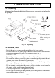
1. UNPACKING AND INSTALLATION 1-1. Unpacking After unpacking the unit, check that all the necessary accessories are included in the package. Ferrite cores *1 Fasteners *1 *1: The number of ferrite cores and fasteners differs according to the area and type of interface. Fig. 1-1 Unpacking 1-2. Handling Notes 1. Install the unit on a stand or table which has a flat, even surface. 2.
ENGLISH 2. PARTS IDENTIFICATION AND NOMENCLATURE Fig.
3. FERRITE CORE INSTALLATION NOTE: Take special care when following the procedures listed below. ■ A ferrite core is necessary on the printer interface cable to prevent the generation of noise. If a parallel interface cable is used, a ferrite core must be installed on the cable. If a serial intserface cable is used, a ferrite core must be installed on the cable for all areas, except the US and Hong Kong. ■ The ferrite core is normally packed so it is open, as shown in Fig 3-2.
■ Clamp the ferrite core onto the interface cable as shown in Fig 3-2. Take care to avoid damaging the interface cable when installing the ferrite core. The ferrite core should be anchored firmly in place with the fastener that comes with it, as shown in Fig 3-3 and 3-4. Fig. 3-5 To install the cash drawer drive cable ferrite core (except for US, HK) ■ Clamp the ferrite core onto the cash drawer drive cable, looping the cable as shown in Fig. 3-2.
4. CONNECTING THE INTERFACE CABLE 4-1. Serial Interface Cable 1 Turn off power for both the host computer and the printer. 2 Insert the connector of the interface cable into the connector on the printer and the other end of the interface cable into the connector for the host computer. 3 Next, tighten the screws on the connectors. Screws Screwdriver Fig. 4-1 Connecting the serial interface cable 4-2. Parallel Interface Cable 1 Turn off the power for both the host computer and the printer.
TABLE DES MATIÈRES 1. DÉBALLAGE ET INSTALLATION ................................................... 8 1-1. Déballage ..................................................................................... 8 1-2. Remarques concernant la manipulation ....................................... 8 2. IDENTIFICATION DES PIÈCES ET NOMENCLATURE ................ 9 3. INSTALLATION DU NOYAU EN FERRITE .................................. 10 4. CONNEXION DU CÂBLE D’INTERFACE ..................................... 12 4-1.
1. DÉBALLAGE ET INSTALLATION 1-1. Déballage Après avoir déballé l’appareil, vérifiez si vous disposez bien de tous les accessoires illustrés ci-après. Attaches pour rouleau de papier (2) Imprimante Axe pour rouleau de papier Anneaux d’arrêt (2) Noyau en ferrite *1 Attache *1 Cartouche de ruban Guide d’utilisation Guide d’installation *1 Le nombre de tores de ferrite et de fixations dépend de la région et du type d’interface. Fig. 1-1 Déballage 1-2. Remarques concernant la manipulation 1.
FRANÇAIS 2. IDENTIFICATION DES PIÈCES ET NOMENCLATURE Fig.
3. INSTALLATION DU NOYAU EN FERRITE N.B.: Prendre des précautions spéciales en suivant les procédures indiquées cidessous: ■ Un tore de ferrite doit être fixé sur le câble d’interface de l’imprimante pour empêcher la production de bruit. En cas d’utilisation d’un câble d’interface parallèle, un tore de ferrite doit être fixé au câble. En cas d’utilisation d’un câble d’interface série, un tore de ferrite doit être fixé au câble pour toutes les régions, sauf pour les Etats-Unis et Hong-Kong.
Installation du tore de ferrite de câble d’interface FRANÇAIS ■ Serrer le tore de ferrite au câble d’interface de la manière indiquée à la Fig. 3-2. Prendre les précautions d’usage pour éviter d’endommager le câble d’interface lors de l’installation du tore de ferrite. Il faut bien immobiliser le tore de ferrite au moyen de l’attache fournie, comme indiqué à la Fig. 3-3 et à la Fig. 3-4. Fig. 3-5 Installation du tore de ferrite de câble de commande de la caisse enregistreuse (sauf É-U et Hong-Kong).
4. CONNEXION DU CÂBLE D’INTERFACE 4-1. Câble d’interface sériel 1 Mettez l’ordinateur hôte et l’imprimante hors tension. 2 Insérez un des connecteurs du câble d’interface dans la prise de l’imprimante et l’autre dans la prise de l’ordinateur hôte. 3 Serrez ensuite les vis des connecteurs. Vis Tournevis Fig. 4-1 Connexion du câble d’interface en série 4-2. Câble d’interface parallèle 1 Mettez l’ordinateur hôte et l’imprimante hors tension.
INHALTSVERZEICHNIS 1. AUSPACKEN UND AUFSTELLUNG .............................................. 14 1-1. Auspacken .................................................................................. 14 1-2. Hinweise zum Umgang .............................................................. 14 2. BESCHREIBUNG UND BEZEICHNUNG DER GERÄTETEILE .. 15 3. INSTALLATION DES FERRITKERNS ............................................ 16 4. ANSCHLUSS DES SCHNITTSTELLENKABELS .......................... 18 4-1.
1. AUSPACKEN UND AUFSTELLUNG 1-1. Auspacken Überprüfen Sie den Kartoninhalt, und vergewissern Sie sich, daß alle unten abgebildeten Teile vorhanden sind. Rollenpapierhalter (2) Drucker Rollenpapierwelle Ferritkern *1 Sicherungsringe (2) Halter *1 *1: Die Anzahl Ferritkerne und Plastikbefestiger sind je nach Ort und Interfacetyp unterschiedlich. Bedienungsanleitung Farbbandkassette Aufstellanleitung Abb. 1-1 Auspacken 1-2. Hinweise zum Umgang 1.
DEUTSCH 2. BESCHREIBUNG UND BEZEICHNUNG DER GERÄTETEILE Abb.
3. INSTALLATION DES FERRITKERNS HINWEIS: Wenden Sie bei der folgenden Montage besondere Vorsicht an. ■ Um Geräuscherzeugung zu verhindern ist ein Ferritkern für das DruckerInterfacekabel notwendig. Wenn ein paralleles Interfacekabel verwendet wird, muß ein Ferritkern für das Kabel installiert werden. Wird ein serielles Interfacekabel verwendet, muß für alle Länder, außer den USA und Hong Kong, ein Ferritkern installiert werden.
Montage des Ferritkerns auf dem Interfacekabel DEUTSCH ■ Legen Sie den Ferritkern, wie in der Abbildung 3-2 gezeigt, um das Interfacekabel. Seien Sie bei der Montage besonders vorsichtig, damit weder das Gehäuse des Ferritkerns noch das Interfacekabel beschädigt werden. Der Ferritkern sollte mit dem Plastikbefestiger an seinem Platz sicher befestigt sein, wie in den Abbildungen 2-2 und 3-4 dargestellt. Abb.
4. ANSCHLUSS DES SCHNITTSTELLENKABELS 4-1. Serielles Schnittstellenkabel 1 Schalten Sie sowohl den Hostcomputer als auch den Drucker aus. 2 Stecken Sie den Stecker des Schnittstellenkabels in die entsprechenden Buchsen am Drucker und am Hostcomputer ein. 3 Ziehen Sie die Schrauben an den Steckern fest. Schrauben Schraubenzieher Abb. 4-1 Anschließen des seriellen Schnittstellenkabels 4-2. Paralleles Schnittstellenkabel Abb.
INDICE 1. DISIMBALLAGGIO E INSTALLAZIONE ...................................... 20 1-1. Disimballaggio ........................................................................... 20 1-2. Note sul maneggio ..................................................................... 20 2. IDENTIFICAZIONE DELLE PARTI E NOMENCLATURA .......... 21 3. INSTALLAZIONE DEL NUCLEO IN FERRITE ............................. 22 4. COLLEGAMENTO DEL CAVO INTERFACCIA ............................ 24 4-1. Cavo interfaccia seriale ...
1. DISIMBALLAGGIO E INSTALLAZIONE 1-1. Disimballaggio Dopo aver disimballato l’unità, controllare che tutti gli accessori siano inclusi nella confezione. Supporti carta in rotolo (2) Stampante Asta carta in rotolo Nucleo in ferrite *1 Anelli di fermo (2) Chiusura *1 *1: Il numero di anelli di ferrite e delle apposite chiusure varia a seconda del paese e del tipo d’interfaccia. Manuale di istruzioni Cartuccia del nastro Manuale di installazione Fig. 1-1 Disimballaggio 1-2. Note sul maneggio 1.
ITALIANO 2. IDENTIFICAZIONE DELLE PARTI E NOMENCLATURA Fig.
3. INSTALLAZIONE DEL NUCLEO IN FERRITE NOTA: Prestare particolare attenzione durante l’esecuzione delle procedure indicate di seguito. ■ Per prevenire la generazione di disturbi elettrici, è necessario dotare il cavo d’interfaccia della stampante di un anello di ferrite. Se si utilizza un cavo d’interfaccia parallelo, è obbligatorio montare un anello di ferrite sul cavo.
Come installare l’anello di ferrite del cavo d’interfaccia ■ Fissare l’anello di ferrite sul cavo d’interfaccia come mostrato in Fig. 3-2. Fare attenzione a non danneggiare il cavo d’interfaccia quando si installa l’anello di ferrite. L’anello di ferrite va saldamente bloccato in posizione con la fascetta di fissaggio fornita in dotazione, come mostrato nelle Fig. 3-3 e 3-4.
4. COLLEGAMENTO DEL CAVO INTERFACCIA 4-1. Cavo interfaccia seriale 1 Spegnere sia il computer ospite che la stampante. 2 Inserire il connettore del cavo interfaccia nel connettore sulla stampante e l’altro capo del cavo interfaccia nel connettore sul computer. 3 Serrare le viti dei connettori. Viti Cacciavite Fig. 4-1 Collegamento del cavo interfaccia seriale 4-2. Cavo interfaccia parallelo 1 Spegnere sia il computer ospite che la stampante.
APPENDIX DIP Switch Setting (Serial Interface) Each of the switches in the DIP switch array is factory preset to the “ON” position. Be sure to turn the power for both the printer and host computer off before changing the setting of the DIP switches. ON OFF ON OFF DIP switch 2 8 8 1 1 8 8 DIP switch 3 DIP switch 4 1 Power off DIP switch 1 DIP switch array ■ DIP-SW 1 Switch Function 1-1 (Not used) 1-2 1-3 Control code CR When turning DC1, DC 3 the power on.
■ DIP-SW 2 Switch 2-1 2-2 2-3 2-4 2-5 2-6 2-7 2-8 Function ON Character code table See table below. Setting the paper width See table below. OFF (Not used) International character set See table below. ■ Character code table (switches 2-1, 2-2) Switch 2-1 2-2 U.S.A. & Europe ON ON IBM #1 OFF ON IBM #2 ON OFF Japan OFF OFF ■ Paper width setting (switches 2-3, 2-4) Switch 2-3 2-4 3.0 or 3.25 inches ON OFF ON ON 2.
■ DIP-SW 3 Switch Function 3-1 3-2 Data transmission rate 3-3 Auto cutting 3-4 control mode (SP347) 3-5 Handshake 3-6 Data word length 3-7 Vertical parity check 3-8 Parity ON OFF See table below.
DIP Switch Setting (Parallel Interface) Each of the switches in the DIP switch array is factory preset to the “ON” position. Be sure to turn the power for both the printer and host computer off before changing the setting of the DIP switches.
■ DIP-SW 2 Switch 2-1 2-2 2-3 2-4 2-5 2-6 2-7 2-8 Function Character code table (See table below) (Not used) Setting the paper width (Not used) ON 3.25 or 3.0-inch OFF 2.25-inch International character set (See table below) ■ Character code table (switches 2-1, 2-2) Switch 2-1 2-2 U.S.A. & Europe ON ON IBM #1 OFF ON IBM #2 ON OFF Japan OFF OFF Switch U.S.A.
Connectors and Signals (Serial Interface) RS-232C Pin no. I/O direction Signal name Function 1 F-GND — 2 TXD OUT Frame ground 3 RXD IN 4 RTS OUT Data transmission request signal. This is always “SPACE” when the printer is turned on. 5 CTS IN This signal changes to “SPACE” when host computer is ready to transmit data. (In this instance, the printer does not check this signal.
20 mA current loop (option) Pin no. Signal name I/O direction Function 9 TTY TXDR — Indicates the ground side of the data signal of 20 mA loop current. 10 TTY TXD OUT Transmitted data of 20 mA current loop. 17 TTY TXDR — Indicates the ground side of the data signal of 20 mA loop current. 18 TTY RXDR — Indicates the ground side of the data signal of 20 mA loop current. 19 TTY RXD IN Received data of 20 mA current loop.
Interface Connections (Serial Intefface) The following is a basic example of interface connections. (For interface connections, refer to the specifications for the respective interface.) An IBM PC type serial port is shown in below.
Connectors and Signals (Parallel Interface) IN 2-9 DATA1-8 IN 10 ACK OUT 11 BUSY OUT 12 18 19-30 31 PAPER OUT OUT SELECTED OUT N/C SIGNAL GND CHASSIS GND +5VDC GND RESET IN 32 ERROR 33 34 35 36 EXT GND COMPULSION OUT N/C – – – 13 14-15 16 17 IN/OUT OUT Function Signals when data is ready to be read. Signal goes from HIGH to LOW (for at least 0.5 microsec.) when the data is available. These signals provide the information of the first to eighth bits of parallel data.
Peripheral Unit Drive Circuit [Drive output 24V, max. 1.0 A] Drive circuit AC power cable: Approx.
MEMO
MEMO
ELECTRONIC PRODUCTS DIVISION STAR MICRONICS CO., LTD. OVERSEAS SUBSIDIARY COMPANIES STAR MICRONICS AMERICA, INC. 536 Nanatsushinya, Shimizu-ku, Shizuoka, 424-0066 Japan Tel: 0543-47-0112, Fax: 0543-48-5013 1150 King Georges Post Road, Edison, NJ 08837-3729 U.S.A. Tel: 732-623-5555, Fax: 732-623-5590 STAR MICRONICS U.K. LTD. Please access the following URL http://www.star-m.jp/eng/dl/dl02.htm for the lastest revision of the manual.