DOT MATRIX PRINTER SP500 SERIES USER’S MANUAL MODE D’EMPLOI BEDIENUNGSANLEITUNG MANUALE DI ISTRUZIONI
Federal Communications Commission Radio Frequency Interference Statement This equipment has been tested and found to comply with the limits for a Class A digital device, pursuant to Part 15 of the FCC Rules. These limits are designed to provide reasonable protection against harmful interference when the equipment is operated in a commercial environment.
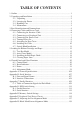
TABLE OF CONTENTS 1. Outline ............................................................................................................... 1 2. Unpacking and Installation ................................................................................ 2 2-1. Unpacking .............................................................................................. 2 2-2. Locating the Printer ...............................................................................3 2-3. Handling Care ..................
1. Outline ENGLISH The SP500 Series Serial Impact Dot Matrix Printer is designed for use with electronic instruments such as POS, banking equipment, computer peripheral equipment, etc. The major features of the SP500 series are as follows: 1. Bi-directional printing at approx. 4 lines/sec. 2. Serial interface or parallel interface. 3. The data buffer allows the unit to receive print data even during printing. 4. Peripheral unit drive circuit enables control of external devices such as cash drawers.
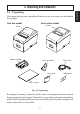
2-1. Unpacking After unpacking the unit, check that all the necessary accessories are included in the package. Tear bar model Auto cutter model Printer Printer H V H ON ER RO R ER RO ER R RO R FE ED PO WER F OF ON N O FE ED FE ED PO WER PO WER Ribbon cartridge V Roll paper guide Rear cover F OF FF O Power cord Switch blind User’s manual Fig. 2-1 Unpacking If anything is missing, contact the dealer where you bought the printer and ask them to supply the missing part.
2-2. Locating the Printer ENGLISH When you locate your printer, keep the following tips in mind: 1. Protect your printer from excessive heat such as direct sunlight or heaters, and keep it away from moisture and dust. 2. Place the printer on a firm, level surface which is fairly vibration-free. 3. A steady power supply that is not subject to power surges should be connected to the printer.
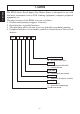
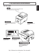
ENGLISH 3. Parts Identification and Nomenclature Tear bar model Cover Protects the printer from dust and reduces noise. Do not open the cover while printing. H ON ER RO R Control panel Features one control switch and two indicators to indicate printer status. Power connector For connection of the power cord. V FE ED F OF PO WER Power switch Turns printer power on and off. Interface connector Connects the printer with host computer.
Auto cutter model ENGLISH Cover Protects the printer from dust and reduces noise. Do not open the cover while printing. H V ON ER RO R FE ED Control panel Features one control switch and two indicators to indicate printer status. F OF PO WER Power switch Turns printer power on and off. OF F Power connector For connection of the power cord. Interface connector Connects the printer with host computer.
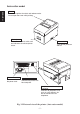
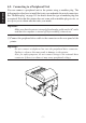
4-1. Connecting the Interface Cable Note: Before connecting/disconnecting the interface cable, make sure that power to the printer and all the devices connected to the printer is turned off. Also make sure the power cable plug is disconnected from the AC outlet. (1) Connect the interface cable to the connector on the rear panel of the printer. (2) In the case of a serial interface, tighten the connector screws. In the case of a parallel interface, fasten the connector clasps.
4-2. Connecting to a Peripheral Unit ENGLISH You can connect a peripheral unit to the printer using a modular plug. The following describes how to install the ferrite core and make the actual connection. See “Modular plug” on page 115 for details about the type of modular plug that is required. Note that this printer does not come with a modular plug or wire, so it is up to you to obtain one that suits your needs.
Note: Before connecting/disconnecting the power cord, make sure that power to the printer and all the devices connected to the printer is turned off. Also make sure the power cable plug is disconnected from the AC outlet. (1) Check the label on the back or bottom of the printer to make sure its voltage matches that of the AC outlet. Also make sure the plug on the power cord matches the AC outlet.
4-4. Turning Power On Make sure that the power cord has been connected as described in 4-3. ENGLISH (1) Set the power switch located on the right side of the printer to on. The POWER lamp on the control panel will light up. H V ON ER RO R FE ED F OF PO WER Power switch Important! We recommend that you unplug the printer from the power outlet whenever you do not plan to use it for long periods.
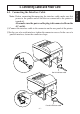
4-6. Installing the Cable ENGLISH Install the cable as shown in the diagram below.
4-7. Switch Blind Installation ENGLISH It is not necessary to install the switch blind. Only install it if it is necessary for you. By installing the switch blind, the following become possible. • Preventing the power switch from being operated by mistake. • Ensuring that other people can not easily operate the power switch. Install the switch blind as shown in the diagram below.
5-1. Tear Bar Model 5-1-1. Loading the Ribbon Cartridge 1 Turn off power to the printer. 2 Open the cover. Cover H Important! 1. Do not touch the print head immediately after printing as it can be extremely hot. 2. Do not touch the cutter blade. · There is a cutter inside the paper outlet slot. Not only should you not put your hand in the paper outlet slot while printing is in progress, never put your hand into the outlet even when printing is not in progress.
ENGLISH Note: When removing the ribbon cartridge, raise the A section and then remove it by holding the B section as shown in Fig. 5-3. B A H V ON ER RO R FE ED F OF PO WE R Fig. 5-3 Removing the ribbon cartridge 5-1-2. Loading the paper Cover H V ON ER RO R FE ED OFF PO WE 1 Open the cover. Important! 1. Do not touch the print head immediately after printing as it can be extremely hot. 2. Do not touch the cutter blade. · There is a cutter inside the paper outlet slot.
Roll paper H V Fig. 5-5 Setting the paper Roll paper Paper feeder H V 5 Insert the edge of the paper into the paper feeder (black plastic part). If inserted correctly, the edge of the paper will pass through the paper exit. 6 Insert the top edge of the paper into the tear bar slot, then mount the cover by reversing the procedure for opening the cover in step 1 above. Note: When the paper end mark appears on the paper, replace the roll paper before it runs out. Tear bar Paper exit Fig.
5-2. Auto Cutter Model 5-2-1. Loading the Ribbon Cartridge ENGLISH 1 Turn off power to the printer. 2 Open the cover. Cover H V ON ER RO R FE ED ON F OF PO WER F OF Power off Important! 1. Do not touch the print head immediately after printing as it can be extremely hot. 2. Do not touch the cutter blade. · There is a cutter inside the paper outlet slot.
Print head Auto cutter Ink ribbon Ribbon feed knob H Notched part Ribbon cartridge ER RO R FE ED V ON F OF PO WE R Fig. 5-10 Loading the ribbon cartridge Note: When removing the ribbon cartridge, raise the A section and then remove it by holding the B section as shown in Fig. 5-11. B A H ON ER RO R FE ED F OF PO WE R Fig. 5-11 Removing the ribbon cartridge – 16 – V ENGLISH 4 Place the ribbon cartridge in the direction shown in Fig. 5-10 and press it down to load it.
5-2-2. Loading the Paper Cover ENGLISH H Important! 1. Do not touch the print head immediately after printing as it can be extremely hot. 2. Do not touch the cutter blade. · There is a cutter inside the paper outlet slot. Not only should you not put your hand in the paper outlet slot while printing is in progress, never put your hand into the outlet even when printing is not in progress. V ON ER RO R FE ED OFF PO WE 1 Open the cover. R Fig.
Paper feeder H V Fig. 5-14 Loading the paper ON ER RO R FE ED F OF PO WE R 5-3. Installing the Roll Paper Guide When using a paper roll with an 58 mm width, install the attached roll paper guide in the groove in the printer. The setting for memory switch 2-A and 2-B must be changed to change the print width from 63 mm to 45 mm. For instructions on setting the memory switch, please refer to the separate Specification Manual. Roll paper guide H V ON ER RO R FE ED OFF PO WE R Fig.
5-4. Clearing Paper Jams ENGLISH 1 Turn the printer off and unplug the power cord from the AC outlet. H 2 Open the cover. Note: Do not touch the print head immediately after printing, as it can be extremely hot. In addition, do not touch the cutter blade on models equipped with the auto cutter. V Cut 3 For auto cutter models, lift up the auto cutter and put it in a vertical position as shown in Fig. 5-9. ON ER RO R FE ED PO WE R OFF Fig.
6-1. Control Panel 1 POWER lamp (Green LED) Lights when the power is ON 2 FEED button Press the FEED button to feed roll paper. 1 POWER lamp (Green LED) 2 FEED button 3 ERROR lamp (Red LED) Indicates various errors in combination with POWER lamp 3 ERROR lamp (Red LED) 6-2. Basic Indicators POWER lamp Power On/Off On/Off No Error On ERROR lamp — Off Buzzer — — – 20 – ENGLISH 6.
6-3. Errors 1) Recoverable error ENGLISH Error Description POWER lamp ERROR lamp Buzzer Recovery Conditions Paper end error On On 4 short beeps (0.13 sec.) repeated twice *1 Waiting for recovery of the printer to be able to print after loading the roll paper Flashes (On: 0.25 Off sec./Off: 0.25 sec.) None *2 Paper near end error (Option) On Flashes (On: 2 sec./ None Off: 2 sec.) *3 Head high temperature detection Flashes (On: 1 sec./Off: 1 sec.
*7 Turn the power OFF, clear the jammed paper or remedy another problem and then turn the power ON. Automatically the printer is recovered if the carriage returns to the home position after turning the power OFF and ON. Restoration is also possible with the n command when in the ESC/POS mode. When the error occurs: STAR Mode: Non recoverable error ESC/POS Mode: Recoverable error *8 For paper jam errors: Clear the jammed paper and change the paper roll if necessary.
6-4. Adjustment Mode ENGLISH There are the following four adjustment modes. The device will enter the adjustment mode if your turn it on while pressing the FEED switch. The Self Printing Mode is entered by releasing the FEED switch after the buzzer sounds once. (Holding down for 2 more seconds) ▼ Adjusting the Dot Alignment Mode is entered by releasing the FEED switch after the buzzer sounds twice. (Refer to Appendix G.
Self-printing will be performed according to the VER. NO., Memory switch settings, DIP switch settings and character order. When the FEED switch is held continuously or when the FEED switch is depressed at the time of the end of selfprinting, only the characters will be printed out repeatedly. – 24 – ENGLISH 6-4-1.
6-4-2. Hexadecimal Dump Mode ENGLISH Each of the signals sent from the computer to the printer will be printed out in hexadecimal code. This function allows you to check if a control code sent to the printer by the program being used is correct or not. The last line is not printed if its data is less than one full line. However, if the FEED switch is pressed, the last line will be printed. To turn off the mode, it is necessary to turn off the printer completely.
1. Introduction ..................................................................................................... 27 2. Déballage et inspection ....................................................................................28 2-1. Déballage ............................................................................................. 28 2-2. Emplacement de l’imprimante .............................................................29 2-3. Précautions de manipulation ...................................
1. Introduction FRANÇAIS L’imprimante série à impact et matrice de points est conçue pour une utilisation avec des instruments électroniques tels que des terminaux points de vente, du matériel bancaire, du matériel périphérique pour ordinateurs, etc. Les caractéristiques principales des modèles de la série SP500 sont les suivantes: 1. Impression bi-directionnelle à 4 lignes/sec. environ. 2. Interface série ou parallèle. 3.
2. Déballage et inspection 2-1. Déballage Modèle avec barre de découpage Modèle avec coupe-papier automatique Imprimante Imprimante H V H ON ER RO R ER RO ER R RO R FE ED PO WER F OF ON N O FE ED FE ED PO WER PO WER Guide du rouleau de papier Cartouche à ruban V Plaque arrière F OF FF O Câble d’alimentation Cache de l’interrupteur Mode d’emploi Fig.
2-2. Emplacement de l’imprimante FRANÇAIS Pour installer correctement l’imprimante, gardez à l’esprit les conseils suivants: 1. Mettez l’imprimante à l’abri de températures excessivement élevées comme en plein soleil ou à proximité d’un appareil de chauffage, et à l’abri de l’humidité et de la poussière. 2. Installez l’imprimante sur une surface stable et de niveau sur laquelle l’imprimante ne sera pas soumise à des vibrations. 3. Veillez à ce que l’imprimante soit branchée sur une source secteur stable.
3. Identification des pièces et nomenclature Modèle avec barre de découpage FRANÇAIS Capot Protège l’imprimante de la poussière et réduit le bruit. Ne pas ouvrir le capot pendant l’impression. H ON ER RO R Panneau de commande Comprend un commutateur de commande et trois témoins indiquant le statut de l’imprimante. Connecteur d’alimentation Pour la connexion du câble d’alimentation.
Modèle avec coupe-papier automatique Capot Protège l’imprimante de la poussière et réduit le bruit. Ne pas ouvrir le capot pendant l’impression. FRANÇAIS H ON ER RO R Panneau de commande Comprend un commutateur de commande et trois témoins indiquant le statut de l’imprimante. V FE ED PO WER F OF Interrupteur d’alimentation Cet interrupteur vous permet de mettre l’imprimante sous découpage et hors découpage. OF F Connecteur d’alimentation Pour la connexion du câble d’alimentation.
4. Câbles de connexion et câble d’alimentation Remarque:Avant de connecter ou déconnecter le câble d’interface, veillez à ce que l’imprimante et tous les appareils qui y sont connectés soient hors découpage. Veillez également à débrancher le câble d’alimentation de la prise secteur. (1) Connectez le câble d’interface à la borne figurant sur le panneau arrière de l’imprimante. (2) Dans le cas d’une interface série, resserrez les vis du connecteur.
4-2. Raccordement d’un appareil périphérique FRANÇAIS Vous pouvez raccorder un appareil périphérique à l’imprimante à l’aide d’une fiche modulaire. Nous expliquons ci-dessous comment installer le tore de ferrite et faire le raccordement proprement dit. Pour les détails sur le type de fiche modulaire à utiliser, reportez-vous à la page 115. Notez que le fil ou la fiche modulaires ne sont pas fournis avec l’imprimante. Vous devrez donc vous les procurer.
Remarque:Avant de connecter ou déconnecter câble d’alimentation, veillez à ce que l’imprimante et tous les appareils qui y sont connectés soient hors découpage. Veillez également à débrancher le câble d’alimentation de la prise secteur. (1) Vérifiez, sur l’étiquette apposée à l’arrière ou au bas de l’imprimante, que la découpage de l’appareil et de la prise secteur correspondent. Veillez également à ce que la fiche à l’extrémité du câble d’alimentation soit adaptée à la prise secteur.
4-4. Mise sous découpage de l’imprimante Assurez-vous d’avoir bien connecté le câble d’alimentation comme décrit à la section 4-3. FRANÇAIS (1) Placez l’interrupteur d’alimentation, situé sur le côté droit de l’imprimante, sur la position sous découpage. La DEL POWER s’allume au panneau des commandes.
4-6. Installation du câble FRANÇAIS Installez le câble, comme indiqué sur le schéma ci-dessous.
4-7. Installation du cache de l’interrupteur L’installation de ce cache n’est pas nécessaire. Ne l’installez que si vous souhaitez : • éviter que l’interrupteur d’alimentation ne soit actionné par erreur ; • vous assurer que personne ne peut l’actionner facilement. FRANÇAIS Installez le cache, comme indiqué sur le schéma ci-dessous. H V ON ON ER RO R FE ED PO WER F OF F OF L’interrupteur peut être activé ON (!) et désactivé OFF (O) en insérant un instrument étroit (stylo à bille, par ex.
5. Installation d’une cartouche à ruban et chargement du papier 5-1. Modèle avec barre de découpage 1 Mettez l’imprimante hors découpage. 2 Ouvrez le capot. Capot H Attention! 1. Ne touchez pas la tête d’impression immédiatement après une impression ; en effet, celle-ci peut être très chaude. 2. Ne pas toucher la lame du coupepapier. · Une lame se trouve dans la fente de sortie de papier.
Remarque: Pour enlever la cartouche à ruban, soulevez la partie A, puis enlevez la cartouche en la tenant par la partie B comme indiqué dans la figure 5-3. B A H V FRANÇAIS ON ER RO R FE ED F OF PO WE R Fig. 5-3 Dégagement de la cartouche du ruban 5-1-2. Chargement du papier Capot H V ON ER RO R FE ED OFF PO WE R Fig. 5-4 Dépose du capot 1 Ouvrez le capot. Attention! 1.
4 En faisant attention au sens du rouleau, mettez le rouleau de papier en place dans le creux, comme indiqué dans la figure 5-5. FRANÇAIS Rouleau de papier H V Fig. 5-5 Chargement du papier Rouleau de papier Fente de sortie de papier H V 5 Insérer le bord du papier dans le mécanisme d’avance de papier (partie en plastique noir). S’il est inséré correctement, le bord du papier ressortira par la fente de sortie de papier.
5-2. Modèle avec coupe-papier automatique 5-2-1. Installation d’une cartouche à ruban 1 Mettez l’imprimante hors découpage. 2 Ouvrez le capot. Capot FRANÇAIS H V ON ER RO R FE ED ON F OF PO WER F OF Hors tension Fig. 5-8 Ouvrez le capot Coupe-papier automatique Attention! 1. Ne touchez pas la tête d’impression immédiatement après une impression ; en effet, celle-ci peut être très chaude. 2. Ne pas toucher la lame du coupepapier. · Une lame se trouve dans la fente de sortie de papier.
Coupepapier automatiTête d’impression que Ruban encreur 4 Mettez la cartouche à ruban en place dans le sens indiqué dans la figure 5-10 et appuyez légèrement sur la cartouche afin qu’elle se mette en place. Si la mise en place de la cartouche n’est pas satisfaisante, appuyez sur la cartouche tout en faisant tourner le bouton d’alimentation du ruban de la cartouche dans le sens de la flèche. 5 Pour tendre le ruban, faites tourner le bouton d’alimentation du ruban de la cartouche dans le sens de la flèche.
5-2-2. Chargement du papier Capot FRANÇAIS H V ON ER RO R FE ED OFF PO WE R Fig. 5-12 Dépose du capot 1 Ouvrez le capot. Attention! 1. Ne touchez pas la tête d’impression immédiatement après une impression ; en effet, celle-ci peut être très chaude. 2. Ne pas toucher la lame du coupepapier. · Une lame se trouve dans la fente de sortie de papier.
Fente de sortie de papier H V Fig. 5-14 Chargement du papier ON ER 5 Insérez l’extrémité du papier dans le mécanisme d’avance de papier (partie en plastique noir). S’il est inséré correctement, le bord du papier passera par la fente coupe-papier automatique. Appuyez sur la touche FEED pour couper le papier. 6 Enlevez le morceau de papier coupé et refermez le capot. Remarque:Quand la marque de fin de papier apparaît sur le papier, remplacez le rouleau avant qu’il soit épuisé.
5-4. Dégagement des bourrages de papier 1 Mettez l’imprimante hors découpage et débranchez le câble d’alimentation de la prise secteur. FRANÇAIS H 2 Ouvrez le capot. Remarque:Ne touchez pas la tête d’impression immédiatement après une impression, car elle risque d’être très chaude. De même, ne touchez pas la lame du coupepapier automatique pour les modèles qui en sont équipés.
6. Panneau de commande et autres fonctions 1 Témoin POWER (DEL verte) S’allume quand l’appareil est sous découpage. 2 Témoin FEED Appuyez sur la touche FEED pour faire avancer le papier. 1 Témoin POWER (alimentation) 2 Témoin FEED (avance de papier) 3 Témoin ERROR (erreur) 3 Témoin ERROR (DEL rouge) Indique des erreurs variées en combinaison avec le témoin POWER. 6-2.
6-3.
*7 Mettez l’appareil hors découpage, dégagez le bourrage de papier ou remédiez à un autre problème, puis mettez l’appareil sous découpage. La récupération de l’imprimante est automatique si le chariot revient dans sa position d’origine une fois l’appareil mis hors puis sous découpage. La restauration est également possible avec la commande n en mode ESC/ POS.
6-4. Mode de réglage Quatre modes de réglage sont disponibles. L’appareil passe en mode de réglage si vous le mettez sous découpage tout en appuyant sur le commutateur FEED. FRANÇAIS Vous pouvez passer en mode Auto-impression en relâchant le commutateur FEED dès que l’avertisseur sonore retentit une fois. (maintenez-le enfoncé au moins 2 secondes) ▼ Passez en mode de réglage d’alignement des points en relâchant le commutateur FEED dès que l’avertisseur sonore retentit deux fois.
6-4-1. Mode Auto-impression FRANÇAIS Le test d’impression sera effectué conformément au réglage du numéro de vérification, du commutateur mémoire des commutateurs DIP et de l’ordre des caractères. Si vous maintenez la pression sur la touche FEED ou si vous appuyez sur la touche FEED à la fin du test d’impression, seuls les caractères seront imprimés à plusieurs reprises.
6-4-2. Vidage hexadécimal FRANÇAIS Chacun des signaux envoyés de l’ordinateur à l’imprimante sera imprimé en code hexadécimal. Cette fonction vous permet de vérifier si un code de contrôle envoyé à l’imprimante par le programme utilisé est correct ou non. La dernière ligne n’est pas imprimée si les données correspondantes ne remplissent pas une ligne complète. Néanmoins, si vous appuyez sur la touche FEED, la dernière ligne sera imprimée.
1. Kurzbeschreibung ............................................................................................ 53 2. Auspacken und Aufstellen ...............................................................................54 2-1. Überprüfen ...........................................................................................54 2-2. Wahl eines Aufstellungsorts für den Drucker ...................................... 55 2-3. Hinweise zum Umgang ............................................................
1. Kurzbeschreibung Der serielle Nadeldrucker der Serie SP500 ist zur Verwendung mit elektronischen Instrumenten wie POS, Bankgeräte, Computerzubehör, etc. gedacht. Die wichtigsten Merkmale der Serie SP500 sind: 1. Bidirektioneller Druck mit ca. 4 Zeilen/s 2. Serielle oder parallele Schnittstelle 3. Pufferspeicher erlaubt, Druckdaten auch während des Druckvorgangs zu empfangen. 4.
2. Auspacken und Aufstellen 2-1. Überprüfen Sie den Kartoninhalt, und vergewissern Sie sich, daß alle unten abgebildeten Teile vorhanden sind. Abreißkantenmodell Auto-Schneidwerkmodell H V H ON ER RO R ER RO ER R RO R FE ED PO WER F OF ON N O FE ED FE ED PO WER PO WER Farbbandkassette V Papierrollenführung Hintere Abdeckung F OF FF O Netzkabel Schalterabdeckung Bedienungsanleitung Abb.
2-2. Wahl eines Aufstellungsorts für den Drucker DEUTSCH Bevor Sie den Drucker auspacken, sollten Sie einige Minuten damit verbringen, einen geeigneten Aufstellungsort auszusuchen. Denken Sie dabei an die folgenden Punkte: 1. Den Drucker vor Hitzequellen wie direktem Sonnenlicht oder Heizkörpern schützen und von Feuchtigkeit und Staub fernhalten. 2. Den Drucker auf einem flachen, aber festen Untergrund aufstellen, wo keine Vibrationen vorhanden sind. 3.
3. Beschreibung und Bezeichnung der Geräteteile Abreißkantenmodell Abdeckung Schüzt den Drucker vor Staub, und reduziert das Betriebsgeräusch. Nicht die Frontabdeckung während des Druckens öffnen. Bedienfeld Hat einen Steuerschalter und zwei Anzeigen zur Anzeige des Druckerzustands. Netzanschluß Zum Anschließen des Netzkabels. V DEUTSCH H ON ER RO R FE ED F OF PO WER Netzschalter Zum Ein-und Ausschalten des Druckers. Schnittstellenbuchse Zum Anschluß des Druckers an den Hostcomputer.
Auto-Schneidwerkmodell Abdeckung Schüzt den Drucker vor Staub, und reduziert das Betriebsgeräusch. Nicht die Frontabdeckung während des Druckens öffnen. H DEUTSCH Bedienfeld Hat einen Steuerschalter und zwei Anzeigen zur Anzeige des Druckerzustands. Netzanschluß Zum Anschließen des Netzkabels. V ON ER RO R FE ED PO WER F OF Netzschalter Zum Ein-und Ausschalten des Druckers. Schnittstellenbuchse Zum Anschluß des Druckers an den Hostcomputer.
4. Anschlußkabel und Netzkabel 4-1. Anschließen des Schnittstellenkabels Hinweis: Vor dem Anschließen/Abtrennen des Schnittstellenkabels stellen Sie sicher, daß der Drucker und alle angeschlossenen Gerät ausgeschaltet sind. Außerdem sollte der Netzstecker abgezogen sein. (2) Bei einer seriellen Schnittstelle ziehen Sie die Steckerschrauben fest. Bei einer parallelen Schnittstelle befestigen Sie die Steckerklammern.
4-2. Anschluß an ein Peripheriegerät Es kann ein Peripheriegerät an den Drucker mit einem Modularstecker angeschlossen werden. Im folgenden wird beschrieben, wie der Ferritkern angebracht und die Verbindung hergestellt wird. Siehe “Modularstecker” auf Seite 115 für den Typ von Modularstecker, der dazu erforderlich ist. Beachten Sie, daß der Drucker nicht mit einem Modularstecker oder Kabel ausgestattet ist. Diese Teile müssen vom Anwender besorgt werden.
Hinweis: Vor dem Anschließen/Abtrennen des Netzkabels stellen Sie sicher, daß der Drucker und alle angeschlossenen Gerät ausgeschaltet sind. Außerdem sollte der Netzstecker abgezogen sein. (1) Durch Überprüfen des Typenschilds auf der Rück- oder Unterseite des Druckers sicherstellen, daß seine Betriebsspannung mit der Spannung der Steckdose übereinstimmt. Stellen Sie ebenfalls sicher, daß der Stecker am Netzkabel der Steckdose entspricht.
4-4. Einschalten Stellen Sie sicher, daß das Netzkabel angeschlossen ist, wie in 4-3 beschrieben. (1) Netzschalter auf der rechten Seite des Geräts auf Ein (ON) stellen. Das POWER-Lämpchen am Bedienfeld leuchtet auf. H V DEUTSCH ON ER RO R FE ED F OF PO WER Netzschalter Wichtig! Wir empfehlen, den Netzstecker aus der Steckdose zu ziehen, wenn der Drucker längere Zeit lang nicht benutzt werden soll.
4-6. Installieren der Kabel Installieren Sie die Kabel wie in den nachfolgenden Abbildungen dargestellt.
4-7. Einsetzen der Schalterabdeckung Es ist nicht notwendig, die Schalterabdeckung zu verwenden. Setzen Sie diese nur ein, wenn für Sie erforderlich ist, daß • der Netzschalter nicht versehentlich betätigt werden kann, • der Netzschalter nicht mehr so einfach von anderen Personen betätigt werden kann. Setzen Sie die Schalterabdeckung wie in den nachfolgenden Abbildungen dargestellt ein.
5. Einlegen von Farbbandkassette und Papier 5-1. Abreißkantenmodell 5-1-1. Einlegen der Farbbandkassette H Wichtig! 1. Nicht den Druckkopf sofort nach dem Drucken berühren, da er sehr heiß sein kann. 2. Nicht die Schneidwerkklinge berühren. · Im Papierauslaßschlitz befindet sich ein Schneidwerk. Niemals die Hände in den Auslaßschlitz stecken, nicht nur während des Druckbetriebs sondern auch wenn der Drucker nicht arbeitet. V ON ER RO R OR R FE ED ON F OF PO WER F OF Netzschalter aus Abb.
Hinweis: Beim Entfernen der Farbbandkassette den Teil A anheben und dann die Kassette an Teil B halten und Abziehen wie in Abbildung 5-3 gezeigt. B A H V DEUTSCH ON ER RO R FE ED F OF PO WE R Abb. 5-3 Farbbandkassette ausbauen 5-1-2. Einlegen von Papier Abdeckung H V ON ER RO R FE ED OFF PO WE 1 Druckerabdeckung öffnen. Wichtig! 1. Nicht den Druckkopf sofort nach dem Drukken berühren, da er sehr heiß sein kann. 2. Nicht die Schneidwerkklinge berühren.
Rollenpapier H V Abb. 5-5 Einlegen von Papier Rollenpapier Papierauslauf H Abreißschlitz Papiereinzug Abb. 5-6 Papier einlegen ER V 5 Die Kante des Papiers in den Papiereinzug (schwarzes Plastikteil) setzen. Wenn richtig eingesetzt, läuft die Kante des Papiers durch den Papierauslauf. 6 Führen Sie die Oberkante des Papiers in den Abreißkantenschlitz ein, und bringen dann die Abdeckung an, indem Sie die Prozedur zum Öffnen der Frontabdeckung (Schritt 1) oben in umgekehrter Reihenfolge ausführen.
5-2. Auto-Schneidwerkmodell 5-2-1. Einlegen der Farbbandkassette Frontabdeckung H V DEUTSCH ON ER RO R FE ED ON F OF PO WER F OF Netzschalter aus Abb. 5-8 Druckerabdeckung öffnen. Schneidwerk 1 Stellen Sie den Netzschalter am Drucker in Aus-Stellung. 2 Druckerabdeckung öffnen. Wichtig! 1. Nicht den Druckkopf sofort nach dem Drukken berühren, da er sehr heiß sein kann. 2. Nicht die Schneidwerkklinge berühren. · Im Papierauslaßschlitz befindet sich ein Schneidwerk.
Druckkopf 4 Die Farbbandkassette in der Richtung einsetzen wie in der Abbildung 5-10 gezeigt und eindrücken, bis sie hörbar einrastet. Wenn die Farbbandkassette nicht richtig sitzt, eingedrückt halten und gleichzeitig den Farbbandknopf in Pfeilrichtung drehen. 5 Um Schlaufen im Farbband aufzuwickeln, den Farbbandzuführknopf der Farbbandkassette in Pfeilrichtung drehen. 6 Das Schneidwerk schließen. 7 Druckerabdeckung schließen.
5-2-2. Einlegen von Papier Abdeckung H DEUTSCH Wichtig! 1. Nicht den Druckkopf sofort nach dem Drukken berühren, da er sehr heiß sein kann. 2. Nicht die Schneidwerkklinge berühren. · Im Papierauslaßschlitz befindet sich ein Schneidwerk. Niemals die Hände in den Auslaßschlitz stecken, nicht nur während des Druckbetriebs sondern auch wenn der Drucker nicht arbeitet. V ON ER RO R FE ED OFF PO WE 1 Druckerabdeckung öffnen. R Abb.
Papiereinzug H Abb. 5-14 Einlegen des Papiers ON ER RO R FE ED F OF PO WE R V 5 Die Papierkante in den Papiereinzug setzen (schwarzes Plastikteil). Wenn richtig eingesetzt, läuft die Papierkante durch den Schlitz des automatischen Papierabschneiders. Drücken Sie die FEED-Taste zum Abschneiden des Papiers. Entfernen Sie das abgeschnittene Stück Papier und schließen die Abdekkung. 6 Die Taste FEED drücken, um das Papier zu schneiden.
5-4. Beheben von Papierstaus 1 Stellen Sie den Netzschalter auf Aus und ziehen Sie den Netzstecker von der Steckdose ab. DEUTSCH H 2 Öffnen Sie die Abdeckung. Hinweis: Berühren Sie nicht den Druckkopf sofort nach dem Druck, da er sehr heiß sein kann. Außerdem darf nicht das Schneidmesser bei Modellen mit automatischer Schneidvorrichtung berührt werden. V Schneiden ON ER RO R FE ED PO WE R OFF Abb.
6. Bedienfeld und andere Funktionen 6-1. Bedienfeld 1 POWER-Lämpchen (grüne LED) Leuchtet in eingeschaltetem Zustand 1 POWERLämpchen (grüne LED) 2 FEED-Taste 3 ERROR-Lämpchen (rote LED) 3 ERROR-Lämpchen (rote LED) Zeigt in Kombination mit dem POWER-Lämpchen verschiedene Fehlerzustände an 6-2. Standardanzeigen POWER-Lämpchen Netz ein/aus Ein/Aus Kein Fehler Ein ERROR-Lämpchen — Aus Summer — — – 72 – DEUTSCH 2 FEED-Taste Die FEED-Taste drücken, um das Rollenpapier vorzutransportieren.
6-3.
*7 Drucker ausschalten, Papierstau oder anderen Fehler beheben und Drucker wieder einschalten. Der Fehler wird automatisch behoben wenn der Druckkopf nach dem Aus- und Wiedereinschalten in die Ausgangsstellung zurückkehrt. Die Wiederherstellung ist im ESC/POS-Modus auch mit dem Befehl n möglich. Wenn der Fehler auftritt, STAR-Modus: Nicht behebbarer Fehler ESC/POS-Modus: Behebbarer Fehler *8 Bei Papierstau: Gestautes Papier entfernen und die Papierrolle bei Bedarf ersetzen.
6-4. Einstellungsmodus Es stehen die folgenden vier Einstellungsmodi zur Verfügung. Durch Einschalten des Geräts bei gleichzeitigem Drücken der FEED-Taste wird der Einstellungsmodus aktiviert. Der Selbstdruckmodus wird durch Loslassen der FEED-Taste nach einmaligem Ertönen des Summers aufgerufen. DEUTSCH (Weiter länger als 2 Sekunden drücken) ▼ Der Punktausrichtungsmodus kann durch Loslassen der FEED-Taste nach zweimaligem Ertönen des Summers aufgerufen werden.
6-4-1. Selbstdruckmodus DEUTSCH Der Selbstdruck wird entsprechend der VER.NO., Memory-Switch- und DIPSchaltereinstellung sowie der Zeichenfolge ausgeführt. Wenn die Taste FEED kontinuierlich gedrückt gehalten wird oder wenn FEED am Ende des Selbstdrucks gedrückt wird, werden nur die Zeichen wiederholt ausgedruckt.
6-4-2. Sedezimale Datenausgabe Bei diesem Befehle werden alle Codes (Zeichencodes und Steuercodes), die vom Computer zum Drucker gesandt werden, in sedezimaler Form ausgedruckt. Der sedezimale Datenausdruck ist nützlich, um zu prüfen, ob vom Drucker ausgegebene Steuercodes richtig sind. Die letzte Zeile wird nicht ausgedruckt, wenn sie nicht vollständig mit Daten gefüllt ist. Wenn die Taste FEED gedrückt wird, wird die letzte Zeile aber gedruckt.
1. Descrizione ......................................................................................................79 2. Disimballaggio e installazione ........................................................................80 2-1. Disimballaggio .....................................................................................80 2-2. Collocazione della stampante .............................................................. 81 2-3. Precauzioni per l’uso.................................................
1. Descrizione La stampante seriale a matrice di impunti a impatto SP500 è stata progettata per l’uso con strumenti elettronici come POS, apparecchiature bancarie, periferiche computer, ecc. Le principali caratteristiche della serie SP500 sono come segue: 1. Stampa bidirezionale a circa 4 righe/sec. 2. Interfaccia seriale o interfaccia parallelo 3. Buffer dati per la ricezione di dati di stampa anche durante la stampa 4.
2. Disimballaggio e installazione 2-1. Disimballaggio Dopo aver disimballato l’unità, controllare che tutti gli accessori necessari siano inclusi nella confezione. Modello con barra di strappo Modello con taglierina automatica Stampante H V H ON ER RO R ER RO ER R RO R FE ED PO WER F OF ON N O FE ED FE ED PO WER PO WER Guida del rotolo di carta Cartuccia nastro V Cavo di alimentazione F OF FF O Coperchio posteriore Mascherina interruttore Manuale di istruzioni Fig.
2-2. Collocazione della stampante Quando si colloca la stampante, tenere presenti le seguenti considerazioni: 1. Proteggere la stampante da calore eccessivo come luce solare diretta o caloriferi e tenerla lontana da umidità e polvere. 2. Collocare la stampante su una superficie stabile e piana che non sia soggetta a vibrazioni. 3. Collegare alla stampante una fonte di alimentazione stabile che non sia soggetta a picchi.
3. Identificazione delle parti e nomenclatura Modello con barra di strappo Coperchio Protegge la stampante dalla polvere e riduce il rumore. Non aprire il coperchio durante la stampa. H ON ER RO R Connettore dell’alimentazione Per il collegamento del cavo di alimentazione FE ED F PO WER OF Interruttore di alimentazione Per accendere e spegnere la stampante. OF F Connettore interfaccia Per collegare la stampante al computer ospite.
Modello con taglierina automatica Coperchio Protegge la stampante dalla polvere e riduce il rumore. Non aprire il coperchio durante la stampa. H ON ER RO R ITALIANO Pannello comandi Dispone di un interruttore di comando e due indicatori dello stato della stampante. Connettore dell’alimentazione Per il collegamento del cavo di alimentazione V FE ED PO WER F OF Interruttore di alimentazione Per accendere e spegnere la stampante.
4. Cavi di collegamento e cavo di alimentazione 4-1. Collegamento del cavo interfaccia Nota: Prima di collegare/scollegare il cavo interfaccia, assicurarsi che la stampante e tutti i dispositivi collegati alla stampante siano spenti. Inoltre assicurarsi che la spina del cavo di alimentazione sia scollegata dalla presa di corrente. (1) Collegare il cavo interfaccia al connettore sul pannello posteriore della stampante. ITALIANO (2) Nel caso di un interfaccia seriale, serrare le viti del connettore.
4-2. Collegamento ad un’unità periferica Si può collegare un’unità periferica alla stampante usando una spina modulare. Di seguito descriviamo come installare l’anello di ferrite ed eseguire il collegamento. Vedere “Modulare necessario” a pagina 115 per dettagli sul tipo di spina modulare necessario. Notare che la stampante non è dotata di spina o filo modulare, che devono essere acquistati in base alle esigenze di impiego.
4-3. Collegamento del cavo di alimentazione opzionale ITALIANO Nota: Prima di collegare/scollegare il cavo di alimentazione, assicurarsi che la stampante e tutti i dispositivi collegati alla stampante siano spenti. Inoltre assicurarsi che la spina del cavo di alimentazione sia scollegata dalla presa di corrente. (1) Controllare l’etichetta sul retro o sotto alla stampante per accertarsi che la tensione corrisponde alla presa della corrente alternata.
4-4. Accensione Assicurarsi che il cavo di alimentazione sia stato collegato come indicato nella sezione 4-3. (1) Regolare su ON l’interruttore di alimentazione situato lato destro della stampante. La spia POWER sul pannello di controllo si illumina. H V ON ER RO R FE ED F OF PO WER ITALIANO Interruttore di alimentazione Importante! Consigliamo di scollegare la stampante dalla presa di corrente quando si prevede di non usarla per un lungo periodo.
4-6. Installazione del cavo Installare il cavo come mostrato nello schema sotto.
4-7. Installazione mascherina dell’interruttore Non è necessario installare la mascherina dell’interruttore. Installarla solo se lo si ritiene necessario. Una volta installata la mascherina dell’interruttore, è possibile quanto segue. • Impedire l’azionamento per errore dell’interruttore di alimentazione. • Impedire ad altre persone di azionare facilmente l’interruttore di alimentazione. Installare la mascherina dell’interruttore come mostrato nello schema sotto.
5. Inserimento della cartuccia nastro e della carta 5-1. Modello con barra di strappo 5-1-1. Inserimento della cartuccia nastro H Importante! 1. Non toccare la testina di stampa subito dopo la stampa perché può essere molto calda. 2. Non toccare la lama della taglierina. · All’interno della fessura di uscita carta si trova una taglierina. Non mettere mai la mano nella fessura di uscita della carta durante la stampa e non mettere mai la mano nella fessura anche quando la stampa non è in corso.
Nota: Quando si rimuove la cartuccia nastro, sollevare la parte A e quindi rimuovere la cartuccia tenendo la parte B come mostrato nella Fig. 5-3. B A H V ON ER RO R FE ED F OF PO WE R Fig. 5-3 Rimuovere la cartuccia del nastro ITALIANO 5-1-2. Inserimento della carta Coperchio H V ON ER RO R FE ED OFF PO WE R Fig. 5-4 Rimozione del coperchio 1 Aprire il coperchio. Importante! 1. Non toccare la testina di stampa subito dopo la stampa perché può essere molto calda. 2.
4 Osservando l’orientamento del rotolo, collocare il rotolo di carta nel vano come mostrato in Fig.5-5. Rotolo di carta V Fig. 5-5 Inserimento della carta Rotolo di carta Alimentatore della carta H V 5 Inserire il bordo della carta nell’alimentatore della carta (parte di plastica nera). Se è inserito correttamente, il bordo della carta passa attraverso l’uscita della carta.
5-2. Modello con taglierina automatica 5-2-1. Inserimento della cartuccia nastro 1 Spegnere la stampante. 2 Aprire il coperchio. Coperchio H V ON ER RO R FE ED ON F OF PO WER F OF ITALIANO Spegnere Fig. 5-8 Aprire il coperchio Taglierina automatica Importante! 1. Non toccare la testina di stampa subito dopo la stampa perché può essere molto calda. 2. Non toccare la lama della taglierina. · All’interno della fessura di uscita carta si trova una taglierina.
Separatore del nastro 4 Inserire la cartuccia nastro nella direzione mostrata nella Fig. 5-10 e premerla in basso per caricarla. Se il caricamento della cartuccia nastro non è soddisfacente, premere in basso la cartuccia nastro girando la manopola di avanzamento nastro in direzione della freccia. 5 Girare la manopola di avanzamento nastro della cartuccia nastro in direzione della freccia per eliminare l’allentamento del nastro. 6 Chiudere la taglierina automatica. 7 Chiudere il coperchio.
5-2-2. Inserimento della carta Coperchio H V ON ER RO R FE ED OFF PO WE R ITALIANO Fig. 5-12 Rimozione del coperchio 1 Aprire il coperchio. Importante! 1. Non toccare la testina di stampa subito dopo la stampa perché può essere molto calda. 2. Non toccare la lama della taglierina. · All’interno della fessura di uscita carta si trova una taglierina.
Rotolo di carta Alimentatore della carta H V 5 Inserire il bordo della carta nell’alimentatore carta (parte di plastica nera). Se è inserito correttamente, il bordo della carta passa attraverso la fessura carta della taglierina automatica. Premere il tasto FEED per tagliare la carta. 6 Rimuovere il pezzo di carta tagliato e chiudere il coperchio. Nota: Quando il segno di fine carta appare sulla carta, sostituire il rotolo prima che finisca. Fig.
5-4. Eliminazione degli inceppamenti della carta 1 Regolare l’interruttore di alimentazione sulla posizione di spegnimento e scollegare la spina del cavo di alimentazione dalla presa di corrente. H 2 Aprire il coperchio. Nota: Non toccare la testina di stampa subito dopo la stampa perché può essere molto calda. Inoltre non toccare la lama della taglierina sui modelli dotati di taglierina automatica. V Tagliare ON ER RO R FE ED PO WE R OFF ITALIANO Fig.
6. Pannello di controllo e altre funzioni 6-1. Pannello di controllo 1 Spia POWER (LED verde) Si illumina quando l’unità è accesa. 2 Tasto FEED Premere il tasto FEED per far avanzare la carta su rotolo. 1 Spia POWER (LED verde) 2 Tasto FEED 3 Spia ERROR (LED rosso) Indica vari errori in combinazione con la spia POWER. ITALIANO 3 Spia ERROR (LED rosso) 6-2.
6-3. Errori 1) Errore ripristinabile ITALIANO Descrizione errore Spia POWER Errore spia Cicalino Errore arresto carta On On Attesa recupero stampante per la stampa dopo l’inserimento del rotolo di carta Errore di carta quasi esaurita (opzione) Lampeggia (On: 0,25 sec./Off: 0,25 sec.) Off 4 bip brevi (0,13 sec.) ripetuti due volte Nessuno On Lampeggia (On: 2 sec./ Off: 2 sec.
*7 Spegnere l’alimentazione, rimuovere la carta inceppata o rimediare un altro problema e quindi riaccendere l’alimentazione. La stampante viene ripristinata automaticamente quando il carrello ritorna alla posizione di riposo una volta commutata l’alimentazione tra OFF e ON. Il ripristino è anche possibile con il comando n quando la stampante si trova nella modalità ESC/POS.
6-4. Modalità regolazione Sono disponibili le quattro modalità di regolazione seguenti. L’apparecchio entrerà nella modalità di regolazione se viene attivato premendo l’interruttore FEED. La modalità di Stampa automatica viene attivata rilasciando l’interruttore FEED dopo che il cicalino suona una volta. (tenere premuto per altri 2 secondi) ▼ La regolazione della modalità di Allineamento dei punti viene attivata rilasciando l’interruttore FEED dopo che il cicalino suona due volte.
6-4-1. Modalità stampa automatica ITALIANO La stampa automatica viene eseguita a seconda del N. VERSIONE, dell’impostazione relativa all’interruttore della memoria, dell’impostazione relativa all’interruttore DIP e all’ordine dei caratteri. Se l’interruttore FEED viene premuto continuamente o viene premuto alla fine della stampa automatica, verranno stampati ripetutamente solo i caratteri.
6-4-2. Modo di scaricamento esadecimale Ciascuno dei segnali inviati dal computer alla stampante viene stampato in codice esadecimale. Questa funzione permette di controllare se un codice di controllo inviato alla stampante dal programma usato è corretto o meno. L’ultima riga non viene stampata se i suoi dati non consistono di una riga completa. Tuttavia, se si preme l’interruttore FEED l’ultima riga viene stampata. Per disattivare questo modo, è necessario spegnere completamente la stampante.
Printing method: Print direction: Number of head pins: Number of print columns: Character set: Font configuration Printing width: Print speed: Line spacing: Paper feed method: Paper feed speed: Paper specifications Paper type: Paper width: Roll diameter: Core: Serial impact dot matrix Bi-directional 9 wires 42 columns ASCII 96 (characters) Extended graphics: 128 × 40 pages (Star mode) 128 × 9 pages (ESC/POS) International characters: 46 (Star mode) 37 (ESC/POS) 7 (Half dots) × 9 or 5 × 9 63 mm (210 dots)/
Tear Bar Model 163 mm 225 mm 140 mm 140 mm 163 mm 225 mm APPENDIX Auto Cutter Model Fig.
Interface Serial interface: Bidirectional parallel interface: Peripheral unit drive circuit: Ambient temperature/humidity Operating temperature: Operating humidity: Storage temperature: Storage humidity: Mechanical Life: Print head life: RS-232C IEEE1284 compatibility and nibble modes 2 circuits (24V, max.
Appendix B: Serial Interface B-1. Pins and Signal Names Pin No. Signal Name Direction Function 1 FG — 2 TXD OUT 3 RXD IN Receive data 4 RTS OUT Always space 5 N.C. 6 DSR 7 SG APPENDIX 8 -19 N.C. 20 DTR Frame ground Transmission data Not connected IN STAR Mode Status of this signal is not checked. ESC/POS Mode In DTR/DSR communication mode when Memory Switch4-5 = 0, indicates whether data receive from host is enabled or disabled.
Pin No. Signal Name Direction 20 DTR OUT 21 - 25 N.C. Function X-On/X-Off Communication Mode Always space, except during following conditions: • Period between reset and communication enabled • During self printing and dot alignment adjustment Not connected 13 1 25 14 B-2. Interface Connections Refer to the interface specifications of the host for details on connecting to its interface connector. The following illustration shows a typical connection configuration.
Appendix C: Parallel Interface The two-way parallel interface is compatible with the IEEE1284 compatibility mode and nibble mode. C-1. Table of Connection Signals for Each Mode APPENDIX Pin No.
Direction 31 In 32 Out 33 Compatibility Mode Signal Name nInit Nibble Mode Signal Name nInit nFault nDataAvail/Data0,4 EXT GND — — 34 Out Compulsion Status 35 Out Logic High — 36 In nSelectIn 1284Active Note: 1. The prefix “n” on the signal name refers to low active signals. If the host does not have any one of the signal lines listed above, two-way communication fails. 2.
Appendix D: DIP Switch Setting D-1. Parallel Interface A DIP switch unit is provided at the bottom of the printer, and can be set as given in the table below. Be sure to set the power switch to off before changing the settings. It is recommended to use a pointed item like a pen or flat-blade driver screw to change the settings. The settings will become effective when the power switch is set to on again. The following is the procedure for changing the settings on DIP switches. 1.
D-2. Serial Interface A DIP switch unit is provided at the bottom of the printer, and can be set as given in the table below. Be sure to set the power switch to off before changing the settings. It is recommended to use a pointed item like a pen or flat-blade driver screw to change the settings. The settings will become effective when the power switch is set to on again. The following is the procedure for changing the settings on DIP switches. 1. Turn the printer off and unplug the power cord. 2.
■ DIP switch Factory presetting: All ON*1 SW No. 1 2 Always ON Auto Cutter Function ON OFF Should be set on Invalid Valid 3 Always ON Should be set on 4 5 6 Command emulation 7 Data Length 8 bits 7 bits 8 9 Parity Check Parity Disabled Odd Enabled Even 10 Handshake DTR/DSR XON/XOFF Star Baud Rate ESC/POS See table below *1 The factory settings for enabling/disabling the auto cutter are as follows.
Appendix E: Memory Switch Settings Memory Switch 0 Hexadecimal Code 0000 1 0000 2 3 0000 0000 4 0000 5 6 0000 0000 7 0000 8 0000 Warning! Changing the memory switch settings can cause the printer to fail to operate correctly. – 114 – APPENDIX Each memory switch is a 16-bit word store in EEPROM. For details on the functions and settings of memory switches, see the separate Specification Manual. The table below shows the factory settings for the memory switches.
Appendix F: Peripheral Unit Driver Circuit This printer is equipped with a circuit for driving peripheral units, such as cash drawers. A 6-pin modular connector for connection of the peripheral unit is located on the back of the printer. To connect to the drive circuit, connect the peripheral unit to the modular connector using a cable supplied by you like that one shown in the figure below. Important! Never connect any other type of plug to the peripheral unit connector.
Drive circuit The recommended drive unit is shown below. 1 F.G With shield 2 TR1 D1 Peripheral unit 1 3 7824 +24V M-GND L1 4 D2 TR2 L2 R3 4.7kΩ 1/4W 5 M-GND Peripheral unit 2 +5V R1 Compulsion switch 6 TR3 R2 Frame ground User side Notes • Peripheral Units 1 and 2 cannot be driven simultaneously. • For continuous driving, do not use drive duty greater than 20%. • The status of the compulsion switch can be known from the following.
Appendix G: Adjusting the Dot Alignment Mode You may never have to use the procedure described in this section, but after you have been using your printer for some time you may find that the dots of some graphics do not align correctly. For example, what should look like: may come out looking like one of the following: or like this This is caused when mechanical parts of the printer get out of alignment. This happens only rarely and you may never experience it at all throughout the life of the printer.
Fig. 6-3 Dot Alignment Adjustment Sample 2 • The long buzzer sounds once more and the setting value is automatically set. The adjusting the dot alignment mode is complete. – 118 – APPENDIX • To adjust, use the FEED switch to select the adjustment pattern from the printout with the smallest gap between the first printing pass and the return printing pass.
Appendix H: Black Mark Sensor Alignment Mode 1. Turn the printer off and unplug the power cord. 2. Remove the screws. Then, remove the DIP switch cover on the bottom of the printer. Power off VR22 1 4 Parallel interface VR22 1 10 APPENDIX Serial interface 3. Since it is adjusted by rotating the volume VR22, check the position of the volume. Prepare a small slotted screwdriver that will fit in the hole. 4. Set the roll paper not for black mark. 5.
ELECTRONIC PRODUCTS DIVISION STAR MICRONICS CO., LTD. OVERSEAS SUBSIDIARY COMPANIES STAR MICRONICS AMERICA, INC. 536 Shimizunanatsusinnya, Shizuoka, 424-0066 Japan Tel: 0543-47-0112, Fax: 0543-48-5013 1150 King Georges Post Road, Edison, NJ 08837-3729 U.S.A. Tel: 732-623-5555, Fax: 732-623-5590 http://www.starmicronics.com Please access the following URL http://www.star-micronics.co.jp/service/frame_sp_spr_e.htm for the lastest revision of the manual. STAR MICRONICS U.K. LTD.