
DOT MATRIX PRINTER USERS MANUAL DP8340
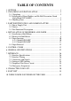

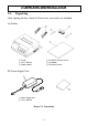
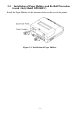
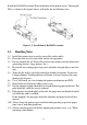
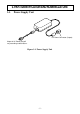
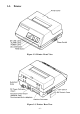
TABLE OF CONTENTS
1. OUTLINE ..............................................................................................1
2. UNPACKING AND INSTALLATION ................................................2
2-1. Unpacking .................................................................................... 2
2-2. Installation of Paper Holders and Re-Roll Prevention Guard
(Only Model DP-8340FC) ...........................................................3
2-3. Handling Notes.............................................................................4
3. PART IDENTIFICATION AND NOMENCLATURE ........................5
3-1. Power Supply Unit .......................................................................5
3-2. Printer ........................................................................................... 6
3-3. Part Functional Description..........................................................7
4. INSTALLATION OF INK RIBBON AND PAPER.............................8
4-1. Installation of Ink Ribbon ............................................................8
4-2. Removal of Ink Ribbon ................................................................ 9
4-3. Paper Insertion ...........................................................................10
4-3-1. Model DP8340FC ...........................................................10
4-3-2. Model DP8340SC ...........................................................11
4-4. Paper Removal ........................................................................... 12
5. CONTROL CODES ............................................................................13
6. GENERAL SPECIFICATIONS..........................................................22
7. INTERFACE .......................................................................................26
7-1. Interface Specifications .............................................................. 26
7-2. Interface Timing ......................................................................... 26
7-3. Connectors and Signals ..............................................................27
7-4. Setting of DIP Switches .............................................................28
7-5. Peripheral Unit Drive Circuit .....................................................29
7-6. Emergency Suspension ..............................................................29
8. CHARACTER CODE LIST................................................................30
9. FONT LIST .........................................................................................39
10. WHEN POWER IS SUPPLIED BY THE USER ............................. 52