TCP300II Series Product Specifications Manual Commands First Release: October 21, 2005 Star Micronics Co., Ltd.
Table of Contents 1. APPLICATION 1 2. PRECAUTIONS FOR PROGRAMMING AND FOR HANDLING 1 3. COMMUNICATION SPECIFICATIONS 2 4. 5. 3-1. Communication Procedures -------------------------------------------------------------------------2 3-2. Transmission Control Matrix-------------------------------------------------------------------------4 3-3. Transmission Control Matrix (Reader Type)----------------------------------------------------5 3-4.
1. APPLICATION This manual describes the commands relating to the TCP300II series printers. 2. PRECAUTIONS FOR PROGRAMMING AND FOR HANDLING • • • • • • • • • • • • The volatile memory writing life is approximately one million times. The expect ed life will be reached by frequent use, which can cause problems in the operation of the printer. Therefore, only use the model set command (91h) and the cleanin g yes/no command (5Bh) when starting up the system.
3. COMMUNICATION SPECIFICATIONS 3-1. Communication Procedures This device communicates with its host using block transmissions of resend requests. When communications are started from the host, the host will transmit a command block to the reader/writer. When the reader/writer receives the command block, it will respond with either of the characters of ACK (normal), NAK (resend request) or DLE (reject).
DLE Sequence Host Command sent → DLE received ← Reader/writer Command received DLE sent See section 2-5. Transmission Control Characters for details regarding ACK, NAK and DLE character codes.
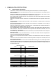
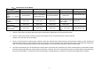
3-2. Transmission Control Matrix Event ACK received NAK received Host status Idling Read and discarded Read and discarded After command is Resend command sent block or process as ACK received waiting to receive communication error ACK After ACK received waiting to receive Reset TCP Reset TCP response After response Reset TCP Reset TCP received ACK After response received NAK Notes: 1.
3-3.
3-4. Command and Response Transfer Formats Command Transfer Formats STX Commands Data String Response Transfer Formats Commands STX Status ETX Data String BCC ETX BCC Data string must be within 1024 bytes. BCC is an exclusive logic sum from the command to ETX. 3-5. Transfer Control Characters The following shows the transmission control character codes and functions.
3-6. Cards for Processing The cards that can be processed are called readable and writable cards. When the card is inserted into the inlet, it is a process targeted card. When the process is completed, the card idles in the machine, and is a process targeted card. When idling in the device, the idling card is a process targeted card regardless of whether there is a card at the inlet. Cards discharged from the device are removal waiting cards and are no longer process target cards.
3-8. Reading the Buffer It is possible to read the buffer when a card that has been read/written is idling. The buffer read commands (29h, 2Ah, 2Bh) obtains the read data stored in the read buffer on the visual card reader/writer. It is possible to get the read data on the track by using the buffer read commands (29h, 2Ah, 2Bh) without transporting a card. The result is high speed reading of the card.
3-9.
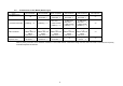
Code Content of Command Class 59h Status Request Command 58h ROM version request command Information 5Ah LED, buzzer control command display 95h Card transport count request command commands 96h Print count request command 5Bh Cleaning button enable/disable command Cleaning 52h Cleaning command commands 5Fh Reset command 90h Communication setting command 91h Model setting command Other commands Model Details 300: 1 Track magnetic head model (TCP300**) 310: 3 Track magnetic head
(2) Status List The following shows the content of status. When there is the status code 20h there is no error. Anything other than 20h, it is recommended to branch the error and processing. Error notification codes may change or be added to without prior notice. Undefined statuses are reserved for the system.
4. COMMAND DETAILS 4-1. (1) Magnetic Stripe Commands Third track read command (Model: 310) General Description This command idles the first track read of a magnetic strip encoded in the following formats.
(2) Second track read command (Models: TCP300/310) General Description This command waits for the second track read of a magnetic strip encoded in the following formats. • 7-bit format conforming to JISX6302* • Reverse 7-bit + 1 parity Reverse direction writing format of the format above* • 6-bit format conforming to ISO 7811/2 first track • 4-bit format conforming to ISO 7811/2 second and third tracks However, the second track is in 70 bpi format.
(4) First track read (status with no card) command (Model: 310) General Description This command idles the first track read of a magnetic strip encoded in the following formats. • 7-bit format conforming to JISX6302* • Reverse 7-bit format Reverse direction writing format of the format above* • 6-bit format conforming to ISO 7811/2 first track • 4-bit format conforming to ISO 7811/2 second and third tracks However, the second track is in 70 bpi format.
(5) Second track read (status with no card) command (Models: 300/310) General Description This command waits for the second track read of a magnetic strip encoded in the following formats. • 7-bit format conforming to JISX6302* • Reverse 7-bit format Reverse direction writing format of the format above* • 6-bit format conforming to ISO 7811/2 first track • 4-bit format conforming to ISO 7811/2 second and third tracks However, the second track is in 70 bpi format.
(7) First track buffer read command (Model: 310) This command acquires the first track buffer data of the following formats. • 7-bit format conforming to JISX6302* • Reverse 7-bit format Reverse direction writing format of the format above* • 6-bit format conforming to ISO 7811/2 first track • 4-bit format conforming to ISO 7811/2 second and third tracks However, the second track is in 70 bpi format. See the first track read command for details.
(9) Third track buffer read command (Model: 310) This command acquires the third track buffer data of the following formats. • 7-bit format conforming to JISX6302* • Reverse 7-bit format Reverse direction writing format of the format above* • 6-bit format conforming to ISO 7811/2 first track • 4-bit format conforming to ISO 7811/2 second and third tracks However, the second track is in 70 bpi format. See the third track read command for details.
(11) Reverse 7 bit format second track data setting command (Models: 300/310) This command sets the write data to the second track with a reverse 7-bit format. Excluding 02h (STX) and 03h (ETX), the write data string must be data from 01h to 7Eh in 0 to 69 bytes. The starting and ending symbols, LRC and parity bit on the magnetic stripe are all automatically applied. A reject response is issued when an error is detected in the write data.
(12) Reverse 7 bit format third track data setting command (Model: 310) This command sets the write data to the third track with a reverse 7-bit format. Excluding 02h (STX) and 03h (ETX), the write data string must be data from 01h to 7Eh in 0 to 69 bytes. The starting and ending symbols, LRC and parity bit on the magnetic stripe are all automatically applied. A reject response is issued when an error is detected in the write data.
(15) 7 bit format third track data setting command (Model: 310) This command sets the write data to the third track with a 7-bit format. Excluding 02h (STX) and 03h (ETX), the write data string must be data from 01h to 7Eh in 0 to 69 bytes. The starting and ending symbols, LRC and parity bit on the magnetic stripe are all automatically applied. A reject response is issued when an error is detected in the write data. Note that this command cannot be used with on models with one magnetic stripe (TCP300).
(17) Second track data setting command (Models: 300/310) This command sets the second track write data. The magnetic format of the write data corresponds to the following formats, but the format that is set abides by the content of the preset memory switches. See Model Setting Commands (91h) for details.
(19) Magnetic stripe write → idle command (Models: 300/310) General Description This command writes magnetic data set by the data setting command. Details of Operation This writing operation starts only when normal write data is set for all specified write tracks. If there is no targeted card, it will wait until one is inserted into the device, then begin to write to the card.
(20) Magnetic stripe write → idle (status with no card) command (Models: 300/310) General Description This command writes magnetic data set by the data setting command. This writes to the magnetic stripe of the targeted card, if one is inserted in the reader/writer. If no target card is inserted in the device, this sets the no card status (22h) to the response block status field and quits the command.
4-2. Print and Erase Commands The speed to write and erase switches according to the ambient environment and card media. To perform a timeout, set the timeout value according to the environment of use. (1) Print expansion buffer clear command This command clears the print expansion buffer only. Image data is expanded in the print expansion buffer by the character (including external characters) by the print character data setting command (41h), and the internal image data expansion command (42h).
(3) Print character data setting command This command expands character data to be printed (including external fonts) in the print expansion buffer. The print data string is composed of the print control header string and the print text data string. The print control header string is composed of the card arrangement direction parameter, the X coordinate specification parameter string, the Y coordinate specification parameter string, and a comma for separating each parameter.
Parameter Explanation Print control header string The print control header string is composed of the card arrangement direction parameter, the X coordinate specification parameter string, the Y coordinate specification parameter string, and a comma for separating each parameter. The print control header string can be omitted altogether. If omitted, the device expands the memory from the next character position after the previous electronic statement.
Notes: The Y coordinate specification parameter indicates the bottom left edge of the text data to expand, so when the set font is 24 dots, the minimum value of the Y coordinate specification value is 23. If the set font is 16 dots, the minimum value of the Y coordinate specification value is 15. JP, GP2312 or GB18030, BIG5 and KR models do not use 16 dot fonts.
• ESC I This expands a specified 16 dot 2-byte external characters FONT in the print expansion buffer memory. ESC ‘I’ next parameter range: ‘0’ to ‘F’ 1 digit configuration ESC “I0” ESC “I1” : : ESC “I9” ESC “IA” : ESC “IE” ESC “IF” • ESC g This expands a specified 24 dot 1-byte external characters FONT in the print expansion buffer memory.
• ESC d Sets the dot space for gaps in single-byte characters. Dot spaces are applied to the right side of characters. ESC ‘d’ next parameter range: ‘0’ to ‘F’ 1 digit configuration • ESC W/w Sets the width size of characters to expand. ESC ‘W’/’w’ next parameter range: ‘1’ to ‘2’ ESC “W1” Specifies normal width fonts. ESC “W2” Specifies double width fonts. 1 digit configuration • ESC V/v Sets the vertical size of characters to expand.
Command Transfer Formats STX 42h Data arrangement specification Response Transfer Formats STX 42h Status ‘,’ Data arrangement X coordinate ETX ‘,’ Data arrangement Y coordinate ‘,’ Expansion image specification number ETX BCC BCC Parameter Explanation • Data arrangement specification parameter To specify whether to use the internal vertically or horizontally, select ‘0’ to ‘3.
(5) External image data expand command This command sets the image data to the rasterized image register buffer (volatile memory). Assuming that the card is horizontally oriented, this registers a maximum of 320 vertical dot image expansion data to the position specified with the X coordinate on the buffer for one page. Turns the image data on the host to text formats, and expands the 320 dot image data as 80 character text format.
(6) External image data expand command This command sets the image data to the rasterized image register buffer (volatile memory). Image data is expanded from the expansion starting X coordinate and the expansion starting Y coordinate (byte: 8 dot units) with the range specified by the image data length. If image data with a number larger than the data specified in the image data length, this automatically increments the X coordinate and expands to the next dot string.
• Expansion starting Y address parameter Specifies whether to expand the registered image Y address to the rasterized image register buffer. Becomes 0 when omitted. Specify in bytes (8 dot units). When making minute adjustments to the image print position in the Y direction, adjust the top and bottom margins on the image data. ‘0’ to “39” • Expansion image data parameter Expresses each 8 dots using two characters of text. LSB specifies the upper side bits; MSB specifies the lower side bits.
(7) Two-byte external character font register command This command registers 24 dot or 16 dot two-byte fonts to the external character buffer (the volatile memory) as external fonts. Along with sizes, 16 fonts can be registered. Reregistering set fonts overwrites the existing ones.
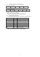
Example Setting A B C D E F G H I J K L M N O P Q R S T U V W X 1 2 ● 3 ● 4 ● ● 5 ● ● 6 ● 7 ● ● ● ● 8 ● ● ● ● ● ● ● 9 ● ● ● ● ● ● ● ● 10 ● ● ● ● ● ● ● ● ● 11 ● ● ● ● ● ● ● ● ● 12 ● ● ● ● ● ● ● ● ● ● 13 ● ● ● ● ● ● ● ● ● ● ● ● ● ● 14 ● ● ● ● ● ● ● ● ● ● 15 ● ● ● ● ● ● ● ● ● 16 ● ● ● ● ● ● ● ● ● 17 ● ● ● ● ● ● ● ● 18 ● ● ● ● ● ● ● 19 ● ● ● ● 20 ● 21 ● ● 22 ● ● 23 ● 24 ● Data: “0 ” “001000001000081020101010” “20000840380400FE0000FF01” “80FF0380FF03C0FF07DEFFF7” “C0FF0780FF0380FF0300FF01” “00FE00003100400004201
(8) Single-byte external character font register command This command registers 24 dot or 16 dot single-byte fonts to the external character buffer to the (volatile memory) as external fonts. Along with sizes, 16 fonts can be registered.
(9) Erase + print → discharge command This command performs the operations specifying the control methods for deleting, printing and discharging. If there is a card idling in the device, it operates immediately. If there is no targeted card, the system will wait until one is inserted into the device, then perform the operation after a card is inserted. After the operation is completed, the print expansion buffer and rasterized image register buffer are not cleared.
Cards after discharged to the front after erasing/printing in the same way as parameter specification 1. This parameter specification method (specifying only the discharge control method) is completely compatible with the conventional erase + discharge command (46h). • Parameter specification example 3 STX 46h 31h , 30h ETX BCC After printing, the card is discharged to front. For example, this applies to one-time media.
(11) Erase → discharge command This command erases the print surface. If there is a card idling in the device, it erases to the card. If there is no targeted card, it will wait until one is inserted into the device, then starts erasing. After erasing, the device will either discharge the card according to the discharge method specification parameter or it will stop while idling and hold the card. Discharged cards wait to be pulled out and are no longer process target cards.
(12) Bar Code Data Setting Commands These commands expand bar code strip patterns and subscript to the print expansion buffer. The print data string is composed of the bar code control header string and the bar code data string.
• ‘,' (Commas) Required to separate parameters. • Bar code status stop code parameter This is necessary only when the bar code type parameters are ‘0,’ ‘1,’ ‘6’ and ‘7.’ When the bar code type parameters are ‘0,’ ‘1’ ‘A’: Sets CODE 128 bar code to code set A. ‘B’: Sets CODE 128 bar code to code set B. ‘C’: Sets CODE 128 bar code to code set C. When the bar code type parameters are ‘6,’ ‘7’ ‘AA’, ‘AB’, ‘AC’, ‘AD’, ‘BA’, ‘BB’, ‘CA’, ‘CB’, ‘CC’, ‘CD’, ‘DA’, ‘DB’, ‘BC’, ‘DC’, ‘BD’ ‘DD' Ex.
Bar Code Data chr(&H10) chr(&H11) chr(&H12) chr(&H13) chr(&H14) chr(&H15) chr(&H16) chr(&H17) chr(&H18) chr(&H19) chr(&H1A) chr(&H1B) chr(&H1C) chr(&H1D) chr(&H1E) chr(&H1F) chr(&H20) chr(&H21) chr(&H22) chr(&H23) chr(&H24) chr(&H25) chr(&H26) chr(&H27) chr(&H28) chr(&H29) chr(&H2A) chr(&H2B) chr(&H2C) chr(&H2D) chr(&H2E) chr(&H2F) chr(&H30) chr(&H31) chr(&H32) chr(&H33) chr(&H34) chr(&H35) chr(&H36) chr(&H37) chr(&H38) chr(&H39) chr(&H3A) chr(&H3B) chr(&H3C) chr(&H3D) chr(&H3E) chr(&H3F) Bar Code Data Str
Bar Code Data Bar Code Data String Suffixes by Code Set CODESET A CODESET B CODESET C chr(&H40) "4 0" → (NUL) ’ 64 chr(&H41) "4 1" → (SOH) a 65 chr(&H42) "4 2" → (STX) b 66 chr(&H43) "4 3" → (EXT) c 67 chr(&H44) "4 4" → (EOT) d 68 chr(&H45) "4 5" → (ENQ) e 69 chr(&H46) "4 6" → (ACK) f 70 chr(&H47) "4 7" → (BEL) g 71 chr(&H48) "4 8" → (BS) h 72 chr(&H49) "4 9" → (HT) i 73 chr(&H4A) "4 A" → (LF) j 74 chr(&H4B) "4 B" → (VT)
• When the bar code type parameters are ‘4’, ‘5’ (ITF) Expresses “0” to “9” numbers with the bar code ITF. With the bar code of this mode, it is possible to expand bar code fonts by transmitting the character to use as an ASCII character. A start and stop code is automatically applied. It is possible to expand bar codes for a maximum of 20 characters with one electronic statement. Ex. For VisualCard1.
4-3. (1) Card Commands Card discharge command This command discharges a card. If there is a card in the device, this will discharge that card. The card follows the discharge method specification parameter and is either discharged to a position where it can be reused, or completely discharged. Cards that are discharged to the reuse position and cards completely discharged are both set to await being removed, and are not process targeted cards.
(3) Card rear side idle command This command transports and idles cards to the idling position on the rear side. Regardless of whether the card in the device is waiting to be removed or is a process targeted card, it is transported to the idling position on the rear side of the device and is idled there. If there is no card in the device, the device waits until a card is inserted, then transports it to the rear side where it is idled. Idled cards are process targeted card.
(5) Card removal wait status cancel command This command makes a card in the device that is waiting removal a process targeted card. A card that is executing the erase + print command, the erase command or the discharge command becomes a card waiting removal by the user. To reread the magnetic stripe data or to print again, either execute this command, or execute the card rear side idle command or the card front side idle command to make it a process targeted card.
4-4. (1) Information Display Commands Status request command This command gets the status of the four card sensors in the device and the cover open sensor. The following shows the sensor status string for each character composed of six characters. Command Transfer Formats STX 59h ETX 5Ah Response Transfer Formats STX 59h Status Sensor status data string ETX The following shows the response block sensor status data string.
(2) ROM version request command This command acquires the ROM version information (model name and version) of the reader/writer. Command Transfer Formats STX 58h ETX 5Bh Response Transfer Formats STX 58h Status ROM information ETX BCC The following shows the response block ROM information data string. V 1.
Use the following codes for the LED color setting data. Code Function Either of 47h (‘G’)/67h (‘g’)/31h (‘1’) Sets to green. Either of 4Fh (‘O’)/6Fh (‘o’)/33h (‘3’) Sets to orange. Either of 52h (‘R’)/72h (‘r’)/32h (‘2’) Sets to red. Use the following codes for LED operation and buzzer setting data.
(5) Print count request command This command requests the number printings, as a reference. The print count data string is 10 digits long. When the power is cut, the transport count less than 10 times is rounded down.
4-5. (1) Cleaning Command Cleaning button enable/disable command This command enables and disables the cleaning button on the front panel. The setting is saved in the non-volatile memory. Command Transfer Formats STX 5Bh Enable/disable parameter Response Transfer Formats STX 5Bh Status ETX ETX BCC BCC Parameter Explanation • Enable/disable parameter ‘0’: Disables the panel cleaning button. Device will not enter cleaning mode even when the button is pressed. ‘1’: Enables the panel cleaning button.
4-6. (1) Other Commands Reset command This command resets the device. The reset command is a priority command that resets the device even when another command is being executed. When the reset command is received while executing another command, the device quits the execution of that command. Command Transfer Formats STX 5Fh ETX 5Ch Response Transfer Formats STX 5Fh Status ETX BCC Resetting the device clears the print buffer area, and the magnetic read/write buffer and initializes the mechanism.
Specifying USB Serial Number This command sets the terminal individual number when using a USB interface. If the serial number is a value between 0 and 9, the host COM number can be value unique to that terminal. The COM port varies with the port to use when the serial number is 0. STX, 90h, ‘U’/‘u’, to 1 digit parameters, ETX, BCC Parameters are described in three digit decimal values. The default serial number is ‘1’. (3) Various setting commands This command sets each of the default settings.
Setting Type and Parameter List (Types are set alphabetic characters and parameter are set by numerical values) Contents Type Parameters Functions Initial Value ANK fonts sizes ‘0’ Two-byte font specification ‘J’/‘j’ ‘1’ ‘1’ Single-byte font specification 24/16 dot font types ‘0’ 24 dot font specification ‘F’/‘f’ ‘0’ ‘1’ 16 dot font specification ANK character ‘0’ Narrow gothic specification ‘B’/‘b’ ‘0’ thickness ‘1’ Enhanced gothic specification Enable magnetic See explanation ‘C’/‘c’ ‘0’ to ‘7’ ‘2’ writin
• 24/16 dot font type specification (US/EU) This command sets the US, and EU destined 24/16 dot fonts for AN characters. Settings using the ESC sequence (ESC, F/f) in the print text data string are enabled only in one electronic statement, but settings using this command function as default settings in the print character data setting command 41h.
• Card arrangement direction setting This command sets the direction for card arrangement. In the print character data setting command (41h), the settings made using this command are enabled for the card arrangement direction if not setting the card arrangement direction and data arrangement coordinate printing control header string.
• Magnetic stripe write retry count setting This command sets the number of times the device will retry to write to the magnetic stripe. Settings using this command function as default settings in the magnetic stripe write → idle command 31h and magnetic stripe write → idle (status with no card) command 32h.
• Two-byte characters gap dot space setting (JP/GP2312 or GB18030, BIG5, KR) This command sets the two-byte characters gap dot space. Settings using the ESC sequence (ESC, D) in the print text data string are enabled only in one electronic statement, but settings using this command function as default settings in the print character data setting command 41h.
• Line gap dot space setting This command sets the line gap dot space. Settings using the ESC sequence (ESC, M/m) in the print text data string are enabled only in one electronic statement, but settings using this command function as default settings in the print character data setting command 41h. STX, 91h, ‘M’/‘m’, line gap dot space setting, ETX, BCC Line gap dot space setting parameters ‘0’: ‘1’: : : ‘9’: ‘A’: ‘B’: ‘C’: ‘D’: ‘E’: ‘F’: Sets the line gap dot space setting to 0 dots.
• Magnetic format reading direction conforming to JISX6302 This command sets the magnetic format reading direction conforming to JISX6302 Settings using this command function as default settings in the first, second, and third track read commands 21h, 22h, 23h, the first, second and third track read (status with no card) commands 25h, 26h, 27h, and the first, second, and third track buffer read commands 29h, 2Ah and 2Bh.
5. MATERIALS 5-1. Switching Firmware Use the following steps to switch the firmware of the device. 1. 2. 3. Install the flash memory loading program into your PC. Copy the firmware to any folder. Turn off the power to the device, then mount either of the applicable interfaces of serial, USB, or LAN. 4. Turn the device’s DIP switch #1 to OFF (right side). The #1 DIP switch is on the side of the me on the insertion side, when looking from the top fo the device. 5.
5-2. Error Display A self-diagnosis test is performed when the LED light sequentially at power on. A self-diagnosis test is performed only, without lighting the LED when recovering from a transport path open state, when the reset command is executed. The result of the test is displayed by the LED and buzzer. Test Results Display Remarks Normal STATUS and buzzer flash one time SRAM error STATUS and buzzer flash two times while CLEANING lights.
5-5.
ELECTRONIC PRODUCTS DIVISION STAR MICRONICS CO., LTD. 536 Nanatsushinya, Shimizu-ku, Shizuoka, 424-0066 Japan Tel : 0543-47-0122 Fax: 0543-48-5013 OVERSEAS SUBSIDIARY COMPANIES STAR MICRONICS AMERICA, INC. 1150 King Georges Post Road, Edison, NJ 08837-3729 U.S.A. Tel : 732-623-5555 Fax: 732-623-5590 http://www.starmicronics.com STAR MICRONICS U.K. LTD. Star House, Peregrine Business Park, Gomm Road, High Wycombe, Bucks, HP13 7DL, U.K. Tel : 01494-471111 Fax: 01494-473333 http://www.starmicronics.co.