TSP1000 SERIES THERMAL PRINTER TSP1000 SERIES USER’S MANUAL MODE D’EMPLOI BEDIENUNGSANLEITUNG MANUALE DI ISTRUZIONI ELECTRONIC PRODUCTS DIVISION STAR MICRONICS CO., LTD. OVERSEAS SUBSIDIARY COMPANIES STAR MICRONICS AMERICA, INC. 536 Shimizunanatsushinya, Shizuoka, 424-0066 Japan Tel: 0543-47-0112, Fax: 0543-48-5013 1150 King Georges Post Road, Edison, NJ 08837-3729 U.S.A. Tel: 732-623-5555, Fax: 732-623-5590 STAR MICRONICS U.K. LTD. Please access the following URL http://www.star-m.jp/eng/dl/dl02.
Federal Communications Commission Radio Frequency Interference Statement This equipment has been tested and found to comply with the limits for a Class A digital device, pursuant to Part 15 of the FCC Rules. These limits are designed to provide reasonable protection against harmful interference when the equipment is operated in a commercial environment.
1. Unpacking and Installation .......................................................................................... 1 1-1. Unpacking .......................................................................................................................... 1 2. Parts Identification and Nomenclature ....................................................................... 2 3. Consumable Parts and AC Adapter ............................................................................ 4 4.
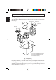
1. Unpacking and Installation ENGLISH 1-1. Unpacking After unpacking the unit, check that all the necessary accessories are included in the package. Paper stopper Switch blind Ferrite core *1 Installation sheet Fastener *2 User’s manual Roll paper holders *3 Roll paper shaft *3 Printer *1: Not included with RS-232C model *2: Not included with RS-232C and USB models *3: TSP1043 model only Fig.
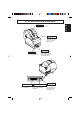
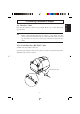
Printer cover Open this cover to load or replace paper. Cover open lever Push this lever in the direction of the arrow to open the printer cover. Control panel Power switch Used to turn on/off power to the printer. Features LED indicators to indicate printer status and switches to operate the printer. Power connector Interface connector For connection to a host computer. Buzzer drive connector Connects to buzzer. Do not connect this to a telephone. –2– For connection of the AC adapter.
Choosing a place for the printer ENGLISH Before actually unpacking the printer, you should take a few minutes to think about where you plan to use it. Remember the following points when doing this. ✓ Choose a firm, level surface where the printer will not be exposed to vibration. ✓ The power outlet you plan to connect to for power should be nearby and unobstructed. ✓ Make sure that the printer is close enough to your host computer for you to connect the two.
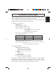
When consumable parts have run out, use those specified in the table below. Make sure that the AC adapter specified in the table is used. Use of consumable parts or an AC adapter which are not specified in the table may result in damage to the printer, fire or electric shock. (1) Roll paper specifications Thermal paper Thickness: 65 to 150 µm Width: 44.5±0.5 to 82.5±0.5 mm Outer roll diameter: Max. ø180 mm (When using drop-in paper loading) Max. ø170 mm (When using roll paper shaft) +0.
ENGLISH (3) AC adapter (option) Model name: PS60 Input: 100 to 240 V AC, 50/60 Hz Output: DC24±5%, 2.0 A (5.0 A Load 10 sec. Max.) CAUTION Access the following URL for the information of the recommended paper. http://www.star-m.jp/eng/dl/dl02.
4-1. Interface Cable Note that the interface cable is not provided. Please use a cable that meets specifications. CAUTION Before connecting/disconnecting the interface cable, make sure that power to the printer and all the devices connected to the printer is turned off. Also make sure the power cable plug is disconnected from the AC outlet. 4-1-1. Serial Interface (RS-232C) Cable (1) Make sure the printer is turn off. (2) Connect the interface cable to the connector on the rear panel of the printer.
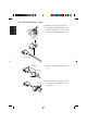
4-1-2. Parallel Interface Cable (1) Make sure the printer is turn off. ENGLISH (2) For only the parallel interface model, affix the ferrite core onto the cable as shown in the illustration below. Ferrite core Interface cable 5 cm maximum (3) Pass the fastener through the ferrite core. Fastener Pull and cut (4) Loop the fastener around the cable and lock it. Use scissors to cut off any excess.
(5) Connect the interface cable to the connector on the rear panel of the printer. ENGLISH (6) Fasten the connector clasps. Parallel interface cable 4-1-3. Connecting USB Cable (1) Make sure the printer is turn off. (2) Affix the ferrite core onto the USB cable as shown in the illustration below and make sure to pass the cable through the cable support as shown in the illustration.
4-1-4. Connecting Ethernet Cable ENGLISH (1) Make sure the printer is turned off. (2) Affix the ferrite core onto the ethernet cable as shown in the illustration below. Ethernet cable Ferrite core 10cm (Maximum) (3) Pass the fastener through the ferrite core. Fastener (4) Loop the fastener around the cable and lock it. Use scissors to cut off any excess. (5) Connect the ethernet cable to the connector on the interface board. Then, connect the other end of the cable to your computer.
You can connect a buzzer drive to the printer using a modular plug. The following describes how to make the actual connection. See “Modular plug” on page 149 for details about the type of modular plug that is required. Note that this printer does not come with a modular plug or wire, so it is up to you to obtain one that suits your needs. CAUTION Make sure that the printer is turned off and unplugged from the AC outlet and that the computer is turned off before making connections.
4-3. Connecting the Optional AC Adapter ENGLISH Note: Before connecting/disconnecting the AC adapter, make sure that power to the printer and all the devices connected to the printer is turned off. Also make sure the power cable plug is disconnected from the AC outlet. (1) Connect the AC adapter to the power cable. Note: Use only the standard AC adapter and power cable. (2) Connect AC adapter to the connector on the printer. (3) Insert the power cable plug into an AC outlet.
4-4. Turning Power On (1) Set the power switch located on the front of the printer to on. The POWER lamp on the control panel will light up. Power switch CAUTION We recommend that you unplug the printer from the power outlet whenever you do not plan to use it for long periods. Because of this, you should locate the printer so that the power outlet it is plugged into is nearby and easy to access. – 12 – ENGLISH Make sure that the AC adapter has been connected as described in 4-3.
4-5. Installing the Cable Install the cable as shown in the diagram below.
It is not necessary to install the switch blind. Only install it if it is necessary for you. By installing the switch blind, the following become possible. • Preventing the power switch from being operated by mistake. • Ensuring that other people can not easily operate the power switch. Install the switch blind as shown in the diagram below. The power switch can be turned ON (!) and OFF (O) by inserting a narrow instrument (ball pen etc.) in the holes in the switch blind.
5. Control Panel and Other Functions ENGLISH 5-1. Control Panel 2 FEED button 1 POWER lamp (Green LED) Lights when the power is ON 2 FEED button Press the FEED button to feed roll paper. 3 ERROR lamp (Red LED) Indicates various errors in combination with POWER lamp 3 ERROR lamp (Red LED) 1 POWER lamp (Green LED) 5-2. Errors (1) Automatically recoverable error POWER lamp ERROR lamp Recovery Conditions Head high temperature detection Flashes at 0.
Error Description POWER lamp ERROR lamp Recovery Conditions RAM error Off Flashes at 1.0 second intervals This is not a recoverable error. Consult dealer for repairs. EERROM error Off Flashes at 0.75 second intervals This is not a recoverable error. Consult dealer for repairs. Flash ROM error Off Flashes at 0.5 second intervals This is not a recoverable error. Consult dealer for repairs. Thermistor error Off Flashes at 1.5 second intervals This is not a recoverable error.
5-3. Self Printing ENGLISH (1) Test Printing Turn the power on while holding the FEED button depressed. Test printing will be performed according to the Ver. No., DIP switch settings and memory switch settings. (2) Hexadecimal Dump Mode Open the printer cover, then turn the power on while holding the FEED button. When the cover is closed, “*** HEX DUMP PRINTING ***” is printed, and the printer enters the Hexadecimal Dump Mode.
6-1. Loading the Roll Paper Loading the roll paper in this printer differs according to the type of paper (dropin roll paper or roll paper that requires the shaft). Load the roll paper according to the procedures on the section 6-2. (1) Push the Cover open lever, and open the printer cover. (2) While observing the direction of the roll, set the roll paper into the hollow, and pull the leading edge of the paper toward you.
ENGLISH (3) Pull on the edge of the paper to remove any slack and then push down both sides of the printer cover to close it. Note: Make sure that the printer cover is securely closed. (4) If the printer cover is closed after turning on the power, the cutter operates automatically and the front end of the paper is cut. Note: If the cutter does not operate after the printer cover is closed, open the cover and close it again securely. (5) If necessary, attach the paper stopper to the paper cover as shown.
CAUTION • Do not operate the cover open lever while pressing on the printer cover with your hand. • Do not pull out paper while the printer cover is closed. • The heating element and the driver IC of the thermal head are easily damaged. Do not touch them with metal objects, sandpaper, etc. • Printing quality may suffer if the thermal head heating element becomes soiled by being touched with your hands. Do not touch the thermal head heating element.
6-2. Paper Loading Methods ENGLISH This printer has two paper loading methods: one when using the roll paper shaft, and one when not using the shaft. The roll paper shaft is not used for drop-in paper loading. Select the paper loading method from the following table according to the type of paper used. Paper width (mm) 44.5 Paper thickness (µm) 65 80 Thickness < 80 Width < 79.5 79.5 Width 82.
There are two different sized roll paper holders: roll paper holders 1 for paper that has a one-inch inner core diameter, and roll paper holders 2 for paper that has a two-inch inner core diameter. Select the roll paper holders according to the size of roll paper used. (1) Install the roll paper holders onto both ends of the roll paper shaft. (2) Adjust the positions of the roll paper holders according to the width of the roll paper used. (3) Insert the roll paper holders and shaft into the roll paper.
6-4. Paper Guide Adjustment ENGLISH When the printer is shipped from the factory, the paper guides and upper guides are adjusted for roll paper with the following width. Paper width: 79.5 ± 0.5 mm (TSP1043) Paper width: 82.5 ± 0.5 mm (TSP1045) When using roll paper with a width other than listed above, perform the following procedure to adjust the paper guides. To adjust the upper guides, refer to “6-5 Upper Guide Adjustment”. (1) Loosen the four screws.
When the printer is shipped from the factory, the upper guides are adjusted for roll paper with a 79.5–82.5 mm width. When using roll paper with a different width, perform the following procedure to adjust the upper guides. (1) Loosen the two screws for the left and right upper guides. (2) Adjust the left and right upper guides according to the width of the roll paper, making sure that each guide is approximately 2 mm to the inside of the edge of the paper.
7. Adjusting the Near-end Sensor ENGLISH Use the following procedure to adjust the near-end sensor so it is compatible with the size of roll paper you are using. 1 Open the printer cover. 2 Determine the correct position of the adjuster from the following three positions according to the paper loading method and the inner core diameter of the roll paper. Position 1: Using drop-in paper loading Position 2: Using roll paper holder 2 (ø50.8 mm inner core) Position 3: Using roll paper holder 1 (ø25.
Paper thickness (µm) When using roll paper with an inside core diameter (A): ø25.4 and outside core diameter (B): ø40 Detected diameter (C) Remaining paper length (Approx. mm) (Approx. m) Level 1 Level 2 Level 3 Level 1 65 Level 2 Level 3 5.6 80 — ø45 — — 105 4.4 — 3.2 (3) Position 3 Paper thickness (µm) When using roll paper with an inside core diameter (A): ø 50.8 and outside core diameter (B): ø58 Detected diameter (C) Remaining paper length (Approx. mm) (Approx.
8. Preventing and Clearing Paper Jams ENGLISH 8-1. Preventing Paper Jams The paper should not be touched during ejection and before it is cut. Pressing or pulling the paper during ejection may cause a paper jam, paper cutting failure or line feed failure. 8-2. Removing Paper Jam If a paper jam occurs, clear it as described below. (1) Set the power switch to off to turn off power to the printer. (2) Push the cover open lever, and open the printer cover.
8-3. Releasing a Locked Cutter WARNING Since working on the cutter may be dangerous, be sure to turn off the printer first. (1) Set the power switch to OFF to turn off the printer. (2) Slide off the front cover to reveal the auto cutter. (3) Remove any jammed paper. CAUTION Be careful not to damage the printer while removing any jammed paper. Since the thermal print head is particularly sensitive, be sure not to touch it.
ENGLISH (4) If the cutter’s moving blade is protruding, rotate the knob in the direction of an arrow to return the moving blade to its home position. When the check window is completely white, the moving blade is at its home position. CAUTION 1) Do not apply extreme pressure to the moving blade. 2) If the moving blade is protruding too much, the printer cover cannot be opened. Trying to open the printer cover may damage the cutter.
Printed characters may become partially unclear due to accumulated paper dust and dirt. To prevent such a problem, paper dust collected in the paper holder and paper transport section and on the surface of the thermal head must be removed periodically. Such cleaning is recommended to be carried out once six month or one million lines. 9-1. Cleaning the Thermal Head To remove blackish dust collected on the surface of the thermal head, wipe it with Isopropyl alcohol (IPA).
ENGLISH – 31 –
1. Déballage et inspection .................................................................................. 33 1-1. Déballage ............................................................................................. 33 2. Identification des pièces et nomenclature .................................................... 34 3. Consommables et adaptateur secteur .......................................................... 36 4. Câbles de connexion et adaptateur secteur .........................................
1. Déballage et inspection 1-1. Déballage Après avoir déballé l’appareil, vérifiez si tous les accessoires nécessaires se trouvent dans la boîte. FRANÇAIS Feuille d’installation Supports de rouleau de Axe de rouleau de papier *3 papier *3 Butée du papier Cache de l’interrupteur Tore de ferrite *1 Attache *2 Mode d’emploi Imprimante *1: Non livré avec le modèle RS-232C *2: Non livré avec les modèles RS-232C et USB *3: Uniquement sur le modèle TSP1043 Fig.
2. Identification des pièces et nomenclature Capot de l’imprimante Levier d’ouverture du capot Poussez ce levier dans le sens de la flèche pour ouvrir le capot de l’imprimante. Panneau des commandes Interrupteur d’alimentation Permet la mise sous et hors tension de l’appareil. Le panneau est équipé de commutateurs permettant la commande de l’imprimante et de DELs indiquant les statuts.
Emplacement de l’imprimante Avant de déballer l’imprimante, déterminez l’emplacement où vous souhaitez l’installer. Veuillez observer les points ci-dessous lors de votre choix. FRANÇAIS ✓ Choisissez une surface stable et de niveau sur laquelle l’imprimante ne sera exposée à aucune vibration. ✓ Assurez-vous que l’emplacement dispose d’une prise secteur proche et d’accès aisé. ✓ Assurez-vous que la distance entre l’imprimante et l’ordinateur-hôte vous permet de les raccorder aisément.
3. Consommables et adaptateur secteur (1) Rouleau de papier, caractéristiques Papier thermique Épaisseur: 65 à 150 µm Largeur: 44,5±0,5 à 82,5±0,5 mm Diamètre extérieur du rouleau : Max. ø180 mm (Lors de l’utilisation du chargement du papier par simple dépôt du rouleau dans l’imprimante) : Max.
(3) Adaptateur secteur (option) Nom du modèle: PS60 Entrée: CA100 à 240 V, 50/60 Hz Sortie: CC24±5%, 2,0 A (charge de 10 sec. à 5,0 A max.) FRANÇAIS ATTENTION Pour obtenir des informations concernant le papier recommandé, consultez l’adresse URL suivante : http://www.star-m.jp/eng/dl/dl02.
4. Câbles de connexion et adaptateur secteur 4-1. Câble d’interface ATTENTION Avant de connecter ou déconnecter le câble d’interface, veillez à ce que l’imprimante et tous les appareils qui y sont connectés soient hors tension. Veillez également à débrancher le câble d’alimentation de la prise secteur. 4-1-1. Câble d’interface série (RS-232C) (1) Assurez-vous que l’imprimante est hors tension. (2) Connectez le câble d’interface à la borne figurant sur le panneau arrière de l’imprimante.
4-1-2. Interface parallèle (1) Assurez-vous que l’imprimante est hors tension. (2) Modèle avec interface parallèle seulement: fixez la grande gaine en ferrite sur le câble comme illustré. FRANÇAIS Tore de ferrite Interface câble (3) Passez l’attache dans le tore de ferrite. 5 cm maximum Attache Tirez et coupez (4) Passez l’attache autour du tore de ferrite et serrez-la. Coupez l’extrémité de l’attache à l’aide de ciseaux.
(5) Connectez le câble d’interface à la borne figurant sur le panneau arrière de l’imprimante. FRANÇAIS (6) Attachez les fermoirs du connecteur. Câble d’interface parallèle 4-1-3. Branchement d’un câble USB (1) Assurez-vous que l’imprimante est hors tension. (2)Attachez le tore de ferrite au câble USB conformément à l’illustration cidessous, et veiller à passer le câble par le support de câble illustré.
4-1-4. Branchement d’un câble ethernet (1) Assurez-vous que l’imprimante est hors tension. FRANÇAIS (2) Attachez le tore de ferrite au câble ethernet conformément à l’illustration. Câble ethernet Tore de ferrite 10 cm (maximum) (3) Passez le collier de serrage par le tore de ferrite. Collier de serrage (4) Passez le collier de serrage autour du câble et immobilisez ce dernier. Coupez l’extrémité excédentaire du collier à l’aide d’une paire de ciseaux.
4-2. Raccordement d’une sonnerie ATTENTION Assurez-vous que l’imprimante est hors tension, qu’elle est débranchée de la prise secteur et que l’ordinateur est hors tension avant d’effectuer les connexions. Connectez le câble de la sonnerie à la borne figurant sur le panneau arrière de l’imprimante. ATTENTION Ne connectez pas une ligne de téléphone à la borne de la sonnerie, sous peine de risquer d’endommager l’imprimante.
4-3. Connexion de l’adaptateur secteur optionnel Remarque:Avant de connecter ou déconnecter l’adaptateur secteur, veillez à ce que l’imprimante et tous les appareils qui y sont connectés soient hors tension. Veillez également à débrancher le câble d’alimentation de la prise secteur. FRANÇAIS (1) Connectez l’adaptateur secteur au câble d’alimentation. Remarque:Utilisez exclusivement l’adaptateur secteur et le câble d’alimentation destinés à l’imprimante.
4-4. Mise sous tension de l’imprimante (1) Placez l’interrupteur d’alimentation, situé à l’avant de l’imprimante, sur la position sous tension. La DEL POWER s’allume au panneau des commandes. Interrupteur d’alimentation ATTENTION Nous vous recommandons de débrancher l’imprimarte du secteur lorsque vous ne comptez pas l’utiliser pendant une période prolongée. Par ailleurs, veillez lors de l’installation à ce que la prise secteur alimentant l’imprimante soit proche et d’accès facile.
4-5. Installation du câble Installez le câble, comme indiqué sur le schéma ci-dessous.
4-6. Installation du cache de l’interrupteur Installez le cache, comme indiqué sur le schéma ci-dessous. L’interrupteur peut être activé ON (!) et désactivé OFF (O) en insérant un instrument étroit (stylo à bille, par ex.) dans les orifices du cache de l’interrupteur. ATTENTION Nous vous recommandons de débrancher l’imprimante du secteur lorsque vous ne comptez pas l’utiliser pendant une période prolongée.
5. Panneau de commande et autres fonctions 5-1. Panneau de commande 1 Témoin POWER (DEL verte) S’allume quand l’appareil est sous tension. 2 Témoin FEED (avance de papier) FRANÇAIS 2 Témoin FEED Appuyez sur la touche FEED pour faire avancer le papier. 3 Témoin ERROR (DEL rouge) Indique des erreurs variées en combinaison avec le témoin POWER. 3 Témoin ERROR (erreur) 1 Témoin POWER (alimentation) 5-2.
Description de l’erreur Témoin POWER Témoin ERROR Conditions de récupération Erreur de mémoire vive Hors tension Clignote à 1,0 seconde d’intervalle Ce n’est pas une erreur récupérable. Consultez votre revendeur pour des réparations. Erreur de mémoire EERROM Hors tension Clignote à 0,75 seconde d’intervalle Ce n’est pas une erreur récupérable. Consultez votre revendeur pour des réparations.
5-3. Auto-impression (1) Essai d’impression Mettez l’appareil sous tension tout en maintenant la touche FEED enfoncée. L’essai d’impression sera effectué en fonction du numéro de version, des réglages du commutateur DIP et des réglages de commutateur de carte d’extension de mémoire. FRANÇAIS (2) Mode de vidage hexadécimal Ouvrez le capot de l’imprimante, puis mettez l’appareil sous tension tout en maintenant la touche FEED enfoncée.
6. Chargement du rouleau de papier Le chargement du rouleau de papier dans cette imprimante est différent selon le type de papier utilisé (rouleau de papier à chargement par simple dépôt ou rouleau de papier nécessitant l’utilisation de l’axe). Chargez le rouleau de papier en suivant les procédures figurant à la section 6-2. (1) Poussez le levier d’ouverture du capot et ouvrez le capot de l’imprimante.
(3) Tirez sur le papier afin de bien le tendre, puis appuyez de part et d’autre du capot de l’imprimante pour le fermer. Remarque: Assurez-vous que le capot de l’imprimante est bien fermé. FRANÇAIS (4) Si le couvercle de l’imprimante est fermé après la mise sous tension, le coupe-papier coupe automatiquement la partie avant du papier. Remarque: Si le papier n’est pas automatiquement coupé après la fermeture du capot, ouvrez à nouveau le capot, puis refermez-le avec soin.
ATTENTION • Ne pas faire fonctionner le levier d’ouverture du capot tout en appuyant sur le capot de l’imprimante avec la main. • Ne pas tirer sur le papier pour le faire sortir quand le capot de l’imprimante est fermé. • L’élément de chauffage et le circuit imprimé de la tête d’impression thermique sont facilement endommagés. Ne pas les toucher avec des objets métalliques, du papier de verre, etc.
6-2. Méthodes de chargement du papier Cette imprimante permet d’utiliser deux méthodes de chargement : en utilisant l’axe de rouleau de papier ou non. L’axe de rouleau de papier n’est pas utilisé pour le chargement du papier par simple dépôt du rouleau. Sélectionnez la méthode de chargement de papier en vous aidant du tableau suivant, selon le type de papier utilisé.
6-3. Réglage du support de rouleau de papier (1) Installez les supports de rouleau de chaque côté de l’axe de rouleau de papier. (2) Réglez les positions sur les supports de rouleau en fonction de la largeur du rouleau de papier utilisé. (3) Insérez les supports et l’axe de rouleau dans le rouleau de papier.
6-4. Réglage des guides papier Lorsque l’imprimante sort de l’usine, les guides papier et les guides supérieurs sont réglés pour des rouleaux de la largeur suivante. Largeur du papier : 79,5 ± 0,5 mm (TSP1043) Largeur du papier : 82,5 ± 0,5 mm (TSP1045) FRANÇAIS Lorsque vous utilisez un rouleau de papier d’une largeur différente de celles figurant dans la liste ci-dessus, effectuez la procédure suivante pour régler les guides papier.
6-5. Réglage des guides supérieurs (1) Dévissez les deux vis des guides supérieurs gauche et droit. (2) Réglez les guides supérieurs gauche et droit selon la largeur du rouleau de papier, en veillant à ce que chaque guide soit environ 2 mm à l’intérieur du bord du papier. Les graduations de la plaque métallique sur le capot sont divisées en segments de 1 mm.
7. Réglage du capteur de fin de rouleau FRANÇAIS Utilisez la procédure suivante pour régler le capteur de fin de rouleau conformément à la taille du rouleau de papier utilisé. 1 Ouvrez le capot de l’imprimante. 2 Déterminez la position correcte du système de réglage à partir des trois positions suivantes, en fonction de la méthode de chargement du papier et du diamètre du rouleau intérieur du rouleau de papier.
(2) Position 2 Quand vous utilisez un rouleau de papier dont le diamètre intérieur du support est de (A) : ø25,4 et le diamètre extérieur de (B) : ø40 Épaisseur du Diamètre détecté (C) Longueur de papier restante papier (µm) (Env. mm) (Env.
8. Prévention et correction de bourrages de papier 8-1. Prévention des bourrages de papier FRANÇAIS Il convient de ne jamais toucher le papier pendant son éjection et avant qu’il soit coupé. Appuyer ou tirer sur le papier pendant son éjection risque de provoquer un bourrage, des problèmes de coupure ou d’avance de ligne. 8-2. Correction de bourrages de papier En cas de bourrage de papier, procédez comme suit afin d’y remédier : (1) Mettez l’appareil hors tension.
8-3. Libération d’une unité de découpage bloquée AVERTISSEMENT Le travail sur l’unité de découpage étant dangereux, n’oubliez pas de mettre avant tout l’imprimante hors tension. (1) Réglez l’interrupteur d’alimentation sur la position hors tension OFF pour mettre l’imprimante hors tension. (2) Faites glisser le couvercle avant pour dégager l’unité de découpage automatique. (3) Enlevez le papier coincé. ATTENTION Faites attention à ne pas endommager l’imprimante pendant que vous enlevez le papier coincé.
(4) Si la lame mobile du coupe-papier dépasse, tournez le bouton dans le sens de la flèche afin de ramener la lame à sa position d’origine. Quand la fenêtre de contrôle est complètement blanche, la lame mobile est dans sa position d’origine. FRANÇAIS ATTENTION 1) N’appliquez pas de pression excessive sur la lame mobile. 2) Si la lame mobile dépasse trop, le capot de l’imprimante ne pourra pas être ouvert.
Les caractères imprimés pourraient devenir partiellement illisibles en raison de l’accumulation de la poussière de papier et de crasse. Afin de prévenir ce genre de problème, il convient de nettoyer régulièrement la poussière qui s’accumule sur le support de papier, les passages du papier et la surface de la tête d’impression. Il est recommandé d’effectuer un tel nettoyage une fois tous les six mois ou après l’impression d’un million de lignes. 9-1.
FRANÇAIS – 63 –
1. Auspacken und Aufstellen ............................................................................ 65 1-1. Überprüfen ...........................................................................................65 2. Beschreibung und Bezeichnung der Geräteteile .........................................66 3. Verbrauchsteile und Netzteil ........................................................................68 4. Anschlußkabel und Netzteil .................................................................
1. Auspacken und Aufstellen 1-1. Überprüfen Sie den Kartoninhalt, und vergewissern Sie sich, daß alle unten abgebildeten Teile vorhanden sind. Papieranschlag Installationsblatt Schalterabdeckung Ferritkern *1 Befestigungsband *2 Bedienungsanleitung DEUTSCH RollenpapierRollenpapierhalter *3 welle *3 Drucker *1: Nicht mit RS-232C mitgeliefert *2: Nicht mit RS-232C- und USB Modellen mitgeliefert *3: Nur Modell TSP1043 Abb.
2. Beschreibung und Bezeichnung der Geräteteile Abdeckung Diese Abdeckung öffnen, um Papier einzusetzen oder zu entnehmen. Bedienfeld Nur Parallel-Schnittschnelle-Modell Zum Ein- oder Ausschalten des Druckers. Mit LED-Anzeigen zur Anzeige des Druckerstatus und Schalter zur Druckerbedienung. Betriebsstromanschluß Schnittstellenbuchse Zum Anschließen an den Hostcomputer. SignaltongebereinheitAnschluß Zum Anschließen des Betriebsstromkabels vom Netzteil.
Wahl eines Aufstellungsorts für den Drucker DEUTSCH Bevor Sie den Drucker auspacken, sollten Sie einige Minuten damit verbringen, einen geeigneten Aufstellungsort auszusuchen. Denken Sie dabei an die folgenden Punkte: ✓ Den Drucker auf einem flachen, aber festen Untergrund aufstellen, wo keine Vibrationen vorhanden sind. ✓ Die verwendete Steckdose soll in der Nähe und frei zugänglich sein. ✓ Sicherstellen, daß der Drucker nahe genug am Computer ist, um die Geräte mit dem Druckerkabel verbinden zu können.
Wenn die Verbrauchsteile verbraucht sind, besorgen Sie Ersatz entsprechend der unten gezeigten Tabelle. Verwendung von Verbrauchsteilen oder Netzteilen, die nicht den unten aufgeführten Beschreibungen entsprechend, kann zu Schäden am Drucker, Bränden oder elektrischen Schlägen führen. (1) Rollenpapierbeschreibung Thermopapier Dicke: 65 bis 150 µm Breite: 44,5±0,5 bis 82,5±0,5 mm Rollen-Außendurchmesser : Max. ø180 mm (Bei Gebrauch von Drop-In-Rollenpapierwechsel) : Max.
(3) Netzteil (Option) Modelbezeichnung: PS60 Eingang: 100 bis 240 V WS, 50/60 Hz 24 V GS±5%, max. 2,0 A (max. 10 s bei 5,0 A Last) Ausgang: ACHTUNG Empfehlungen zu den zu verwendenden Papiersorten sind im Internet bei der folgenden URL erhältlich: http://www.star-m.jp/eng/dl/dl02.
4. Anschlußkabel und Netzteil 4-1. Schnittstellenkabel Beachten Sie, daß das Schnittstellenkabel nicht mitgeliefert ist. Bitte verwenden Sie ein Kabel, das den Spezifikationen entspricht. 4-1-1. Serielles Schnittstellenkabel (RS-232C) (1) Stellen Sie sicher, daß der Drucker ausgeschaltet ist. (2) Schließen Sie das Schnittstellenkabel an die Buchse an der Rückseite des Druckers an. (3) Befestigen Sie die Steckerk-Schrauben.
4-1-2. Parallele Schnittstelle (1) Stellen Sie sicher, daß der Drucker ausgeschaltet ist. (2) Nur beim Parallel-SchnittschnelleModell, Befestigen Sie den großen Ferritkern am Kabel, wie das in der folgenden Abbildung gezeigt wird. Ferritkern DEUTSCH Kable (3) Führen Sie den Kabelbinder durch den Ferritkern. Maximum 5 cm Kabelbinder Ziehen und abschneiden (4) Führen Sie den Kabelbinder um das Kabel und sperren Sie ihn. Schneiden Sie überschüssiges Band mit einer Schere ab.
(5) Schließen Sie das Schnittstellenkabel an die Buchse an der Rückseite des Druckers an. Paralleles Schnittstellenkabel 4-1-3. Anschließen des USB-Kabels (1) Stellen Sie sicher, daß der Drucker ausgeschaltet ist. (2) Bringen Sie den Ferritkern am USB-Kabel an, wie in der Abbildung unten gezeigt und stellen Sie sicher, das Kabel durch die Kabelhalterung zu führen, wie in der Abbildung gezeigt. – 72 – DEUTSCH (6) Befestigen Sie die Steckerklammern.
4-1-4. Anschließen des Ethernet-Kabels (1) Stellen Sie sicher, daß der Drucker ausgeschaltet ist. (2) Bringen Sie den Ferritkern auf dem Ethernet-Kabel an, wie in der Abbildung unten gezeigt. Ethernet-Kabel Ferritkern DEUTSCH (3) Führen Sie die Befestigung durch den Ferritkern. 10 cm (Maximum) Befestigungsteil (4) Führen Sie das Befestigungsteil um das Kabel und sperren es. Schneiden Sie überstehende Teile ab. (5) Schließen Sie das Ethernet-Kabel am Stecker an der Schnittstellenkarte an.
4-2. Anschließen an eine Signaltongebereinheit Sie können eine Signaltongebereinheit mit einem Modularstecker an den Drukker anschließen. Im folgenden wird die Herstellung der Verbindung beschrieben. Siehe “Modularstecker” auf Seite 149 für den Typ von Modularstecker, der dazu erforderlich ist. Beachten Sie, daß der Drucker nicht mit einem Modularstecker oder Kabel ausgestattet ist. Diese Teile müssen vom Anwender besorgt werden.
4-3. Anschließen des optionalen Netzteils Hinweis:Vor dem Anschließen/Abtrennen des Netzteils stellen Sie sicher, daß der Drucker und alle angeschlossenen Gerät ausgeschaltet sind. Außerdem sollte der Netzstecker abgezogen sein. (1) Schließen Sie das Netzteil an das Netzkabel an. Hinweis:Verwenden Sie nur das vorgesehene Netzteil und Netzkabel. (2) Das Netzteil am Stecker des Druckers anschließen. (3) Stecken Sie den Netzstecker des Netzteils in eine Steckdose ein.
4-4. Einschalten Stellen Sie sicher, daß das Netzteil angeschlossen ist, wie in 4-3 beschrieben. DEUTSCH (1) Den Netzschalter vorne am Gerät auf Ein (ON) stellen. Das POWERLämpchen am Bedienfeld leuchtet auf. Netzschalter ACHTUNG Wir empfehlen, den Netzstecker aus der Steckdose zu ziehen, wenn der Drucker längere Zeit lang nicht benutzt werden soll. Der Drucker sollte vorzugsweise an einem Platz aufgestellt werden, der leichten Zugang zur Netzsteckdose gewährt.
4-5. Installieren der Kabel Installieren Sie die Kabel wie in den nachfolgenden Abbildungen dargestellt.
4-6. Einsetzen der Schalterabdeckung Es ist nicht notwendig, die Schalterabdeckung zu verwenden. Setzen Sie diese nur ein, wenn für Sie erforderlich ist, daß • der Netzschalter nicht versehentlich betätigt werden kann, • der Netzschalter nicht mehr so einfach von anderen Personen betätigt werden kann. DEUTSCH Setzen Sie die Schalterabdeckung wie in den nachfolgenden Abbildungen dargestellt ein. Der Netzschalter kann durch Einführen eines spitzigen Gegenstandes (Kugelschreiber usw.
5. Bedienfeld und andere Funktionen 5-1. Bedienfeld 1 POWER-Lämpchen (grüne LED) Leuchtet in eingeschaltetem Zustand 2 FEED-Taste 2 FEED-Taste Die FEED-Taste drücken, um das Rollenpapier vorzutransportieren. DEUTSCH 3 ERROR-Lämpchen (rote LED) 3 ERROR-Lämpchen (rote LED) Zeigt in Kombination mit dem POWER-Lämpchen verschiedene Fehlerzustände an. 1 POWER-Lämpchen (grüne LED) 5-2.
Fehlerbeschreibung POWER-Lämpchen ERROR-Lämpchen Behebungsbedingungen Papierschnitt-Fehler Aus Blinkt im Abstand von 1,0 s Dies ist ein nicht behebbarer Fehler. Der Kundendienst muß bezüglich Reparatur kontaktiert werden. EERROM-Fehler Aus Blinkt im Abstand von 0,75 s Dies ist ein nicht behebbarer Fehler. Der Kundendienst muß bezüglich Reparatur kontaktiert werden. Flash-ROMFehler Aus Blinkt im Abstand von 0,5 s Dies ist ein nicht behebbarer Fehler.
5-3. Selbstdruck (1) Testdruck Das Gerät einschalten, während die FEED-Taste gedrückt gehalten wird. Der Testdruck wird entsprechend der Ver. Nr., den DIP-Schalter-Einstellungen und den Speicherschalter-Einstellungen ausgeführt. DEUTSCH (2) Sedezimaler Datenausdruck Die Druckerabdeckung öffnen, und dann einschalten, während die FEEDTaste gedrückt gehalten wird.
6. Einlegen der Papierrolle 6-1. Einlegen des Rollenpapiers (1) Den Abdeckung-Öffnen-Hebel drücken, und die Druckerabdeckung öffnen. (2) Unter Beachtung der richtigen Einsetzrichtung der Rolle die Papierrolle in die Vertiefung legen und die Vorderkante des Papiers nach vorne ziehen.
(3) Ziehen Sie an der Papierkante, um Durchhang zu beseitign und drükken Sie dann beide Seiten der Druckerabdeckung zum Schließen nach unten. Hinweis: Sicherstellen, daß die Druckerabdeckung fest geschlossen ist. DEUTSCH (4)Wenn die Druckerabdeckung nach dem Einschalten geschlossen wird, arbeitet das Schneidwerk automatisch, und das vordere Papierende wird abgeschnitten. Hinweis: Wenn das Schneidwerk nach dem Schließen der Druckerabdeckung nicht arbeitet, öffnen Sie die Abdeckung und schließen sie wieder.
ACHTUNG • Nicht den Lösehebel der Abdeckung betätigen, während mit der Hand auf die Druckerabdeckung gedrückt wird. • Nicht das Papier bei geschlossener Druckerabdeckung herausziehen. • Das Heizelement und der Treiber-Chip des Thermalkopfes werden leicht beschädigt. Diese Teile nicht mit Metallgegenständen, Sandpapier usw. berühren. • Die Druckqualität kann nachlassen, wenn das ThermalkopfHeizelement durch Berührung mit der Hand verschmutzt wird. Nicht das Thermalkopf-Heizelement berühren.
6-2. Verfahren zum Papiereinlegen Bei diesem Drucker gibt es zwei Verfahren zum Papiereinlegen: eins mit Rollenpapierwelle und eins ohne Welle. Die Rollenpapierwelle wird bei DropIn-Papierwechsel nicht benutzt. Wählen Sie das Papiereinlegeverfahren aus folgender Tabelle je nach benutztem Papier.
6-3. Einstellen des Rollenpapierhalters Es gibt Rollenpapierhalter in zwei unterschiedlichen Größen: Rollenpapierhalter 1 für Papier mit einem Kern-Innendurchmesser von 1 Zoll und Rollenpapierhalter 2 für Papier mit einem Kern-Innendurchmesser von 2 Zoll. Wählen Sie die Papierhalter je nach Größe der verwendeten Papierrolle. Rollenpapierwelle Rollenpapierhalter 2 Rollenpapierwelle Rollenpapierhalter 1 – 86 – DEUTSCH (1) Die Papierrollenhalter auf beide Enden der Rollenpapierwelle aufsetzen.
6-4. Einstellen der Papierführung Bei Lieferung sind die Papierführungen und oberen Führungen für Rollenpapier mit folgender Breite eingestellt. Papierbreite: 79,5 ± 0,5 mm (TSP1043) Papierbreite: 82,5 ± 0,5 mm (TSP1045) Wenn Sie Rollenpapier mit einer anderen Breite als oben angegeben verwenden, führen Sie folgendes Verfahren aus, um die Papierführungen einzustellen. Zum Einstellen der oberen Führungen, siehe “6-5 Einstellen der oberen Führungen”. DEUTSCH (1) Die vier Schrauben lösen.
6-5. Einstellen der oberen Führung (1) Die beiden Schrauben für die linke und rechte obere Führung lösen. (2) Die linke und rechte obere Führung je nach Breite des Rollenpapiers einstellen. Achten Sie dabei darauf, daß jede Führung die Papierkante um etwa 2 mm überlappt. Die Skalen auf der Metallplatte an der Abdeckung sind in 1 mm-Abschnitte Markierungen unterhalb der Skalen werden für unterteilt.
7. Einstellung des Endanäherungs-Sensors Den Endanäherungs-Sensor auf folgende Weise justieren, damit er der Größe der verwendeten Papierrolle entspricht. DEUTSCH 1 Die Druckerabdeckung öffnen. 2 Bestimmen Sie die korrekte Position des Einstellers unter den folgenden drei Positionen je nach Papiereinlegeverfahren und Kern-Innendurchmesser des Rollenpapiers.
(2) Position 2 Papierdicke (µm) Bei Gebrauch von Rollenpapier mit einem Kern-Innendurchmesser (A): ø25,4 und Kern-Außendurchmesser (B): ø40 Erkannter Durchmesser (C) Restpapierlänge (Etwa mm) (Etwa m) Stufe 1 Stufe 2 Stufe 3 Stufe 1 65 Stufe 2 Stufe 3 5,6 80 — ø45 — — 105 4,4 — 3,2 Papierdicke (µm) Bei Gebrauch von Rollenpapier mit einem Kern-Innendurchmesser (A): ø50,8 und Kern-Außendurchmesser (B): ø58 Erkannter Durchmesser (C) Restpapierlänge (Etwa mm) (Etwa m) Stufe 1 Stufe 2 Stufe
8. Verhindern und Beheben von Papierstau 8-1. Verhindern von Papierstau Das Papier soll beim Ausgeben und vor dem Schneiden nicht berührt werden. Wenn das Papier beim Ausgeben gedrückt oder gezogen wird, kann ein Papierstau, ein Abschneidfehler oder ein Zeilenvorschubfehler verursacht werden. 8-2. Beheben von Papierstau Wenn ein Papierstau auftritt, beheben Sie ihn wie folgt. DEUTSCH (1) Stellen Sie den Netzschalter auf Aus, um den Drucker auszuschalten.
8-3. Freigeben eines gesperrten Schneidmessers Wenn das automatische Schneidmesser sperrt oder das Papier nicht schneidet, wie folgt verfahren. WARNUNG Da Arbeiten am Schneidmesser gefährlich sein können, immer zuerst den Drucker ausschalten. (2) Die Frontabdeckung abschieben, um das Schneidmesser freizulegen. (3) Gestautes Papier entfernen. ACHTUNG Darauf achten, nicht den Drucker nicht beim Entfernen von gestautem Papier zu beschädigen.
(4) Wenn die bewegliche Klinge des Schneidmessers hervorsteht, den knopf in Pfeilrichtung drehen, und die bewegliche Klinge in Grundstellung zurückstellen. Wenn das Prüffenster vollständig weiß ist, ist die bewegliche Klinge in Grundstellung. ACHTUNG 1) Nicht starken Druck auf die bewegliche Klinge ausüben. 2) Wenn die bewegliche Klinge zu sehr hervorsteht, kann die Druckerabdeckung nicht geöffnet werden. Wenn versucht wird, die Abdekkung zu öffnen, kann das Schneidmesser beschädigt werden.
9. Regelmäßige Reinigung Die Druckzeichen können durch Ansammlung von Papierstaub und anderem Schmutz unscharf werden. Um das zu verhindern, muß im Papierhalter und in der Papiertransportstufe angesammelter Staub von Zeit zu Zeit entfernt werden. Diese Reinigung sollte einmal alle sechs Monate oder einmal nach jeder Million Zeilen ausgeführt werden. Zum Entfernen von schwärzlichem Staub auf der Oberfläche des Thermalkopfes diesen mit Isopropylalkohol (IPA) abwischen.
DEUTSCH – 95 –
1. Disimballaggio e installazione ...................................................................... 97 1-1. Disimballaggio .....................................................................................97 2. Identificazione delle parti e nomenclatura .................................................. 98 3. Parti soggette a consumo e trasformatore CA ..........................................100 4. Cavi di collegamento e trasformatore CA .................................................102 4-1.
1. Disimballaggio e installazione 1-1. Disimballaggio Dopo aver disimballato l’unità, controllare che tutti gli accessori necessari siano inclusi nella confezione. Foglio di installazione Fermacartar Mascherina interruttore Anello di ferrite *1 Manuale di istruzioni Fascetta di fissaggio *2 Fermi del rotolo di carta *3 Asse del rotolo di carta *3 Stampante ITALIANO *1: Non incluso con il modello RS-232C *2: Non incluso con i modelli RS-232C e USB *3: Solo modello TSP1043 Fig.
2. Identificazione delle parti e nomenclatura Coperchio stampante Aprire questo coperchio per inserire o sostituire la carta. Leva di apertura coperchio Pannello di controllo Interruttore di alimentazione Usarlo per accendere/spegnere la stampante. Dispone di indicatori LED che indicano lo stato della stampante e di interruttori per controllare la stampante. Connettore di alimentazione Connettore interfaccia Per il collegamento al computer ospite.
Scelta di un luogo per la stampante Prima di disimballare la stampante, decidere dove si desidera installarla. Tenere presenti i seguenti punti. ITALIANO ✓ Scegliere una superficie stabile e in piano, dove la stampante non sia esposta a vibrazioni. ✓ La presa di corrente che si intende usare per la stampante deve essere vicina e libera da ostacoli. ✓ La stampante deve essere abbastanza vicina al computer da permettere il collegamento tra i due.
3. Parti soggette a consumo e trasformatore CA (1) Carta in rotolo specifiche Carta termica Spessore: 65 a 150 µm Larghezza: 44,5±0,5 a 82,5±0,5 mm Diametro esterno rullo: Mass. ø180 mm (quando il rotolo di carta viene inserito direttamente) Mass.
(3) Trasformatore CA (opzionale) Nome modello: PS60 Ingresso: Da 100 a 240 V CA, 50/60 Hz Uscita: 24±5%CC, 2,0 A (5,0 A carico 10 sec. mass.) CAUTELA Accedere alla seguente URL per informazioni sulla carta consigliata. http://www.star-m.jp/eng/dl/dl02.
4. Cavi di collegamento e trasformatore CA 4-1. Cavo interfaccia Notare che il cavo interfaccia non è in dotazione. Si prega di usare un cavo che corrisponde alle specifiche. CAUTELA Prima di collegare/scollegare il cavo interfaccia, assicurarsi che la stampante e tutti i dispositivi collegati alla stampante siano spenti. Inoltre assicurarsi che la spina del cavo di alimentazione sia scollegata dalla presa di corrente. (1) Assicurarsi che la stampante sia spenta.
4-1-2. Interfaccia parallelo (1) Assicurarsi che la stampante sia spenta. (2) Solo per il modello a interfaccia parallelo, fissare l’anello di ferrite al cavo come mostrato nell’illustrazione qui sotto. Anello di ferrite ITALIANO Cavo 5 cm massimo (3) Far passare la fascetta di fissaggio attraverso l’anello di ferrite. Fascetta di fissaggio Tirare e tagliare (4) Avvolgere la fascetta intorno al cavo e fissarla. Usare delle forbici per tagliare la parte in eccesso.
(5) Collegare il cavo interfaccia al connettore sul pannello posteriore della stampante. (6) Fissare i morsetti del connettore. 4-1-3. Collegamento del cavo USB (1) Assicurarsi che la stampante sia spenta. (2) Applicare l’anello di ferrite al cavo USB come mostrato nell’illustrazione sotto e assicurarsi di far passare il cavo attraverso il fermacavo come mostrato nell’illustrazione.
4-1-4. Collegamento del cavo Ethernet (1) Assicurarsi che la stampante sia spenta. (2) Applicare l’anello di ferrite al cavo Ethernet come mostrato nell’illustrazione sotto. Cavo Ethernet Anello di ferrite 10cm (massimo) (3) Far passare il fermo attraverso l’anello di ferrite. Fermo ITALIANO (4) Far passare il fermo intorno al cavo e bloccarlo. Usare delle forbici per tagliare la parte in eccesso. (5) Collegare il cavo Ethernet al connettore sulla scheda interfaccia.
4-2. Collegamento ad un’unità cicalino Si può collegare un’unità cicalino alla stampante usando una spina modulare. Di seguito descriviamo come eseguire il collegamento. Vedere “Modulare necessario” a pagina 149 per dettagli sul tipo di spina modulare necessario. Notare che la stampante non è dotata di spina o filo modulare, che devono essere acquistati in base alle esigenze di impiego.
4-3. Collegamento del trasformatore CA opzionale Nota: Prima di collegare/scollegare il trasformatore CA, assicurarsi che la stampante e tutti i dispositivi collegati alla stampante siano spenti. Inoltre assicurarsi che la spina del cavo di alimentazione sia scollegata dalla presa di corrente. (1) Collegare il trasformatore CA al cavo di alimentazione. Nota: Usare solo il trasformatore CA e cavo di alimentazione standard. (2) Collegare il trasformatore CA al connettore sulla stampante.
4-4. Accensione Assicurarsi che il trasformatore CA sia stato collegato come indicato nella sezione 4-3. ITALIANO (1) Regolare su ON l’interruttore di alimentazione situato sul davanti della stampante. La spia POWER sul pannello di controllo si illumina. Interruttore di alimentazione CAUTELA Consigliamo di scollegare la stampante dalla presa di corrente quando si prevede di non usarla per un lungo periodo.
4-5. Installazione del cavo Installare il cavo come mostrato nello schema sotto.
4-6. Installazione mascherina dell’interruttore Non è necessario installare la mascherina dell’interruttore. Installarla solo se lo si ritiene necessario. Una volta installata la mascherina dell’interruttore, è possibile quanto segue. • Impedire l’azionamento per errore dell’interruttore di alimentazione. • Impedire ad altre persone di azionare facilmente l’interruttore di alimentazione. ITALIANO Installare la mascherina dell’interruttore come mostrato nello schema sotto.
5. Pannello di controllo e altre funzioni 5-1. Pannello di controllo 1 Spia POWER (LED verde) Si illumina quando l’unità è accesa. 2 Tasto FEED 2 Tasto FEED Premere il tasto FEED per far avanzare la carta su rotolo. 3 Spia ERROR (LED rosso) Indica vari errori in combinazione con la spia POWER. 3 Spia ERROR (LED rosso) 1 Spia POWER (LED verde) ITALIANO 5-2.
Descrizione dell’errore Spia POWER Spia ERROR Behebungsbedingungen Errore RAM Spenta Lampeggia a intervalli di 1,0 secondi Questo errore è senza recupero. Consultare il rivenditore per riparazioni. Errore EERROM Spenta Lampeggia a intervalli di 0,75 secondi Questo errore è senza recupero. Consultare il rivenditore per riparazioni. Errore Flash ROM Spenta Lampeggia a intervalli di 0,5 secondi Questo errore è senza recupero. Consultare il rivenditore per riparazioni.
5-3. Stampa automatica (1) Stampa di prova Accendere l’unità tenendo premuto il tasto FEED. La stampa di prova viene eseguita nell’ordine di numero di versione, impostazioni degli interruttori DIP e impostazioni dell’interruttore di memoria. ITALIANO (2) Modo di scaricamento esadecimale Aprire il coperchio stampante, quindi accendere l’unità tenendo premuto il tasto FEED. Quando si chiude il coperchio viene stampato “*** HEX DUMP PRINTING***” e la stampante passa al modo di scaricamento esadecimale.
6. Inserimento del rotolo di carta 6-1. Inserimento del rotolo di carta La modalità di inserimento del rotolo di carta nella stampante varia in funzione del tipo di carta (rotolo di carta da inserire direttamente o rotolo di carta da inserire prima sull’asse). Inserire il rotolo di carta secondo le procedure descritte nella sezione 6-2. ITALIANO (1) Spingere la leva di apertura coperchio e aprire il coperchio stampante.
(3)Tirare il bordo della carta per eliminare eventuali allentamenti e quindi abbassare entrambi i lati del coperchio stampante per chiuderlo. Nota: Assicurarsi che il coperchio stampante sia saldamente chiuso. ITALIANO (4) Se il coperchio stampante è chiuso dopo l’accensione, la taglierina agisce automaticamente e il bordo anteriore della carta viene tagliato. Nota: Se la taglierna non funziona dopo che si è chiuso il coperchio stampante, aprire il coperchio e chiuderlo di nuovo saldamente.
CAUTELA • Non azionare la leva di apertura del coperchio mentre si preme sul coperchio stampante con la mano. • Non estrarre la carta con il coperchio stampante chiuso. • L’elemento riscaldante e il circuito integrato pilota sulla testina termica si danneggiano facilmente. Non toccarli con oggetti metallici, carta vetrata, ecc. • Se l’elemento riscaldante della testina termica si è sporcato perché è stato toccato con le mani, la qualità di stampa può risentirne.
6-2. Metodi di inserimento carta Con questa stampante si utilizzano due metodi di inserimento carta: uno prevede l’utilizzo dell’asse del rotolo di carta, l’altro no. Quando la carta viene inserita direttamente, infatti, non si utilizza l’asse del rotolo. Servirsi della tabella seguente per determinare il metodo di inserimento carta in funzione del tipo di carta utilizzata.
6-3. Regolazione dei fermi del rotolo di carta I fermi del rotolo di carta presentano due diverse dimensioni: i fermi 1 per la carta con nucleo dal diametro interno di 1 pollice ed i fermi 2 per la carta con nucleo dal diametro interno di 2 pollici. Selezionare i fermi in funzione delle dimensioni del rotolo carta utilizzato. (1) Installare i fermi del rotolo carta ad entrambe le estremità del relativo asse. (2) Regolare la posizione dei fermi secondo la larghezza della carta utilizzata.
6-4. Regolazione delle guide della carta Alla consegna della stampante, le guide carta e le guide superiori sono regolate per un rotolo di carta della larghezza seguente. Larghezza carta: 79,5 ± 0,5 mm (TSP1043) Larghezza carta: 82,5 ± 0,5 mm (TSP1045) Quando si utilizza un rotolo di carta di larghezza diversa da quanto indicato sopra, procedere alla regolazione delle guide della carta nel modo seguente. Per regolare le guide superiori, consultare la parte “6-5 Regolazione delle guide superiori”.
6-5. Regolazione delle guide superiori (1) Allentare le due viti delle guide superiori sinistra e destra. (2) Regolare le guide superiori sinistra e destra in funzione della larghezza del rotolo di carta, facendo attenzione a posizionare ciascuna guida 2 mm all’interno del bordo della carta. Le graduazioni sulla piastra di metallo del coperchio sono suddivise in segmenti di 1 mm.
7. Regolazione del sensore di esaurimento prossimo Usare il seguente procedimento per regolare il sensore di esaurimento prossimo in modo che sia compatibile con le dimensioni del rotolo di carta usato. 1 Aprire il coperchio stampante. 2 Determinare la posizione corretta del regolatore tra le tre posizioni seguenti in funzione del metodo di inserimento carta e del diametro interno del nucleo del rotolo di carta.
(2) Posizione 2 Spessore carta (µm) Quando si utilizza un rotolo di carta con diametro interno del nucleo (A): ø25,4 e diametro esterno del nucleo (B): ø40 Diametro individuato (C) Lunghezza carta rimanente (mm circa) (m circa) Livello 1 Livello 2 Livello 3 Livello 1 65 Livello 2 Livello 3 5,6 80 — ø45 — — 105 4,4 — 3,2 (3) Posizione 3 150 Livello 1 Livello 2 Livello 3 Livello 1 Livello 2 Livello 3 — ø69 — — 6,5 — B A Centro del rotolo di carta C Nota: 1) Prima che la mac
8. Prevenzione e soluzione degli inceppamenti della carta 8-1. Prevenzione degli inceppamenti della carta La carta non deve essere toccata durante l’espulsione e prima che sia tagliata. Se si preme o si tira la carta durante l’espulsione si può verificare un inceppamento della carta, un mancato taglio della carta o un avanzamento di riga mancato. 8-2. Eliminazione degli inceppamenti della carta Se si verifica un inceppamento della carta, eliminarlo come descritto di seguito.
8-3. Rilascio della taglierina bloccata Se la taglierina automatica si blocca o non taglia la carta, procedere come segue. ATTENZIONE Poiché lavorare con la taglierina può essere pericoloso, non dimenticare di spegnere prima la stampante. (1) Regolare l’interruttore di alimentazione su OFF per spegnere la stampante. (2) Spostare il coperchio anteriore per scoprire la taglierina automatica. CAUTELA Fare attenzione a non danneggiare la stampante durante la rimozione della carta inceppata.
(4) Se la lama mobile della taglierina sporge, girare la manopola in direzione della freccia per riportare la lama mobile alla sua posizione di partenza. Quando la finestrella di controllo appare completamente bianca, la lama mobile è nella sua posizione di partenza. CAUTELA 1) Non applicare estrema pressione alla lama mobile. 2) Se la lama mobile sporge eccessivamente, non è possibile aprire il coperchio stampante. Se si tenta di aprire il coperchio stampante si può danneggiare la taglierina.
9. Pulizia periodica I caratteri stampati possono diventare parzialmente poco chiari a causa dell’accumulo di polvere di carta e sporcizia. Per evitare tale problema, è necessario rimuovere periodicamente la polvere di carta accumulata nel comparto carta, nella sezione di trasporto carta e sulla superficie della testina termica. Si consiglia di eseguire questa pulizia una volta ogni sei mesi oppure ogni milione di righe stampate. 9-1. Pulizia della testina termica 9-2.
ITALIANO – 127 –
Appendix A: Specifications A-1. General Specifications Direct line thermal printing Max. 1440 dots/sec. (180 mm/sec.) 203 dpi: 8 dots/mm (0.125 mm/dot) Factory default : 72 mm (TSP1043) : 80 mm (TSP1045) (5) Number of print columns 53 (12 × 24 dots) (6) Roll paper Refer to chapter 3 for details on the recommended roll paper. (7) Overall dimension 161 (W) × 307 (D) × 249 (H) mm (8) Weight Approx. 3.0 kg (9) Noise Approx.
A-2. Auto Cutter Specifications (1) Cutting frequency (2) Thickness of paper Max. 20 cuts per minute 0.065 ~ 0.150 mm A-3. Interface RS232C serial interface/Two-way parallel interface (IEEE1284)/USB interface/ Ethernet interface/Wireless LAN Interface A-4. Electrical Characteristics (1) Input Voltage DC 24V±10% (2) Current Consumption Operating: Approx. 2.0 A (at ASCII printing) Peak: Approx. 10 A Stand-by: Approx. 0.1 A (3) Power Connector APPENDIX Pin No.
A-6. Environmental Requirements (1) Operating Temperature Humidity 5°C to 45°C 10% to 90% RH (without condensation) (%RH) 34°C90% RH 90 Relative humidity 80 40°C65% RH 60 45°C50% RH 40 Operating environment range 20 10 0 10 20 30 40 50 (2) Transport/storage (except for paper) Temperature -20°C to 60°C Humidity 10% to 90% RH (without condensation) A-7. Reliability (1) LIFE (2) Cutter life 20 million lines (based on an average printing rate of 12.
A-8. Black Mark Specifications When using the paper-end sensor as a black mark sensor, the following settings are recommended. Reverse side of the paper Printing direction 1+-0.81 (mm) B mm Cutting location Black Mark 2.5 mm Printing area A mm 5 ± 1 mm C mm APPENDIX Printing surface is on the front side of the paper Min. 15 mm Note: The paper is cut at the location shown above when the memory switch is set to the default setting for the printing start location offset value. 1.
3. PCS value The PCS value of the black marks that will be printed should be a minimum of 0.90 (90%). Note: If the PCS value of the black marks does not meet the specification listed above, page skipping and page length detection errors may occur. To avoid problems, make sure that the specified PCS value is used. Note: 1) If the top margin is insufficient, page skipping errors may occur. To avoid problems, set the top margin carefully. 2) The printing area setting should not exceed the black mark pitch. 5.
6. Example of printing area setting An example of the settings for the printing area when not using reverse paper feeding is shown below. Black mark pitch (dimension A): 100 mm Top margin: 12 mm Bottom margin: 3 mm + (100 mm × 0.03) = 6 mm Given the above settings, the printing area must be set to 82 mm or less (100 mm - 12 mm - 6 mm = 82 mm). Note: 1) Be careful when setting the print layout for pre-printed paper.
Appendix B: Dip Switch Setting Two DIP switches are provided at the bottom of the printer, and can be set as given in the table below. Be sure to set the power switch to off before changing the settings. It is recommended to use a pointed item like a pen or flat-blade driver screw to change the settings. The settings will become effective when the power switch is set to on again. The following is the procedure for changing the settings on DIP switches. 1. Make sure the printer is turned off. APPENDIX 2.
B-1. Parallel Interface Model ON ON OFF No. 1 2 3 4 5 6 7 8 OFF No.
B-2. Sperial Interface (RS-232C) Model ON ON OFF No. 1 2 3 4 5 6 7 8 OFF No.
The following is the procedure for changing the settings on DIP switch No. 3. 1. Turn off the printer and all components connected to it. 2. Remove the 2 screws. 3. Remove the serial interface board unit. 4. Change the setting of the DIP switches. 5. Replace the serial interface board unit. Then secure it with the screws. 6. Turn on the printer and all components connected to it. ON APPENDIX OFF No.
B-3. USB Interface Model ON ON OFF No. 1 2 3 4 5 6 7 8 OFF No.
B-4. Ethernet Interface Model ON ON OFF No. 1 2 3 4 5 6 7 8 OFF No.
DIP-SW 3 LED DIP-switch 3 Switch Function 3-1 Always OFF 3-2 Initialization of settings 3-3 Always OFF 3-4 ON OFF Should be set to off Valid Invalid Should be set to off #9100 Multi-session (Maximum 8 sessions) Valid Invalid The factory settings of DIP switch are all OFF. The firmware must be ver.2.02 or later. ■ LED Display Lights when other party connection is recognized as 10BASE-T. Lights when packets are received.
B-5. Wireless LAN Interface Model OFF ON No. 1 2 DIP-SW DIP Switch LED DIP Switch 1 2 ON OFF Fixed at OFF Initialize of setting information — The factory settings of DIP switch are all off. LED Display Green : Lights when pockets are received. APPENDIX Installing the Printer Driver and the LPR Port Driver Set To use the wireless LAN interface from Microsoft’s Windows 95/98 and ME, the “Star LPR Port Driver Set” along with the printer driver is necessary.
*This product contains Transmitter Module which conforms to the R&TTE Directive. *This roduct ontains Transmitter odule FCC ID: 4B6180210. *This roduct ontains Transmitter odule IC: 844A-66180210. *Strictly observe the export control laws of the country for export when exporting this product. Installing the Ferrite Core (Wireless LAN Model for EU Only) Install the ferrite core onto the buzzer drive cable to prevent radio interference. Use the ferrite core only for the wireless LAN model in the EU.
Connecting the buzzer drive cable Connect the buzzer drive cable to the connector on the printer. Then, connect the other end of the cable to the buzzer drive circuit.
Appendix C: Parallel Interface The two-way parallel interface is compatible with the IEEE1284 compatibility mode and nibble mode. Refer to the separate Specification Manual for details. Pin No.
Appendix D: Serial Interface (RS-232C) D-1. RS-232C Connector Pin No. Signal name Direction 25 Pin 9 Pin 1 F-GND — 2 3 TXD OUT 3 2 RXD IN 4 7 RTS OUT 5 6 N/C Function Frame ground Transmission data Receive data Same as DTR signal. Not used APPENDIX 8 CTS IN Status of this signal is not checked. 6 DSR IN STAR Mode Status of this signal is not checked. ESC/POS Mode In DTR/DSR communication mode, indicates whether data receive from host is enabled or disabled.
Pin No. Signal name Direction 25 Pin 9 Pin Function DIP SW 1-6 Printer status OFF ON 1. During the period from when the power is turned on (including resetting using the interface) to when the printer is ready to receive data. BUSY BUSY 2. During the self printing. BUSY BUSY 3. When the cover is open. - BUSY 4. When the printer stops printing due to a paper-end. - BUSY 5. During macro executing standby status. - BUSY 6. When an error has occurred. - BUSY BUSY BUSY 7.
D-2. Cable Connections The followings are a recommended interface cable connections. Printer side (D-sub 25 pin) Host side 25 pin 9 pin FG 1 1 TXD 2 2 3 TXD RXD 3 3 2 RXD RTS 4 4 7 RTS CTS 5 5 8 CTS DSR 6 6 6 DSR SG 7 7 5 SG DTR 20 8 1 DCD INIT 25 20 4 DTR FG Note: Use shielded wire less than 3m in length.
Appendix E: USB, Ethernet and Wireless LAN Interface E-1. USB Interface Specifications 1. General Specification: Conforms to USB 2.0 Specifications 2. Communication Speed: USB Full Speed Mode (12 Mbps) 3. Communication Method: USB Bulk Transmission Mode 4. Power Specifications: USB Self-power Function 5. Connector: USB Up-Stream Port Connector (USB Type-B) 1. General Specification: Conforms to IEEE802.3 2. Communication Media: 10 Base-T (Connectable to 100 Base-T) 3.
Appendix F: Buzzer Driver Circuit This printer is equipped with a circuit for driving the buzzer. A 6-pin modular connector for connection of the buzzer is located on the back of the printer. To connect to the drive circuit, connect the buzzer to the modular connector using a cable supplied by you like that one shown in the figure below. Caution Never connect any other type of plug to the buzzer connector.
Drive circuit The recommended drive unit is shown below. [ Drive Circuit ] 1 2 F.G 2SD1866 +24V M-GND 6 D1 7824 Buzzer 3 4 Drive Output: 24V, Max. 1.0A 1 6-P Modular jack connector Printer side User side Reference 2SD1866 Circuit Configuration C R3 R4 APPENDIX B E R3=3.5K R4=300 Note: 1) Pin 1 must be shield drain wire connected to buzzer device frame ground. 2) For continuous driving, Maximum drive output is 0.1A.
Appendix G: Memory Switch Settings Each memory switch is stored in EEPROM. For details on the functions and settings of memory switches, see the separate Specification Manual. The table below shows the factory settings for the memory switches. Memory Switch Hexadecimal Code 0 0000 1 2 0000 0000 3 0000 4 0001(TSP1043) or 0000(TSP1045) 8 0000 9 0000 CAUTION Changing the memory switch settings can cause the printer to fail to operate correctly.
Federal Communications Commission Radio Frequency Interference Statement This equipment has been tested and found to comply with the limits for a Class A digital device, pursuant to Part 15 of the FCC Rules. These limits are designed to provide reasonable protection against harmful interference when the equipment is operated in a commercial environment.
TSP1000 SERIES THERMAL PRINTER TSP1000 SERIES USER’S MANUAL MODE D’EMPLOI BEDIENUNGSANLEITUNG MANUALE DI ISTRUZIONI ELECTRONIC PRODUCTS DIVISION STAR MICRONICS CO., LTD. OVERSEAS SUBSIDIARY COMPANIES STAR MICRONICS AMERICA, INC. 536 Nanatsusinya, Shimizu-ku, Shizuoka, 424-0066 Japan Tel: 0543-47-0112, Fax: 0543-48-5013 1150 King Georges Post Road, Edison, NJ 08837-3729 U.S.A. Tel: 732-623-5555, Fax: 732-623-5590 STAR MICRONICS U.K. LTD. Please access the following URL http://www.star-m.