THERMAL PRINTER TSP2000 SERIES USER’S MANUAL MODE D’EMPLOI BEDIENUNGSANLEITUNG MANUALE DI ISTRUZIONI
Federal Communications Commission Radio Frequency Interference Statement This equipment has been tested and found to comply with the limits for a Class A digital device, pursuant to Part 15 of the FCC Rules. These limits are designed to provide reasonable protection against harmful interference when the equipment is operated in a commercial environment.
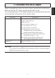
1. Parts Identification and Nomenclature .........................................................1 2. Consumable Parts and AC Adapter ..............................................................3 3. Connecting Cables and AC Adapter ..............................................................4 3-1. Interface Cable .......................................................................................4 3-2. Connecting to a Peripheral Unit .............................................................
Please access the following URL http://www.star-micronics.co.jp/service/frame_sp_spr_e.htm for the lastest revision of the manual. ENGLISH ENGLISH Appendix D: Serial Interface ............................................................................ 96 D-1. RS-232C Connector ............................................................................. 96 D-2. Cable Connections ............................................................................... 97 D-3. Electrical Characteristics ...........
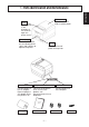
Printer cover Open this cover to load or replace paper. Lever Pull this lever in the direction of the arrow to open the printer cover. Control panel Features LED indicators to indicate printer status and switches to operate the printer. Power connector For connection of the AC adapter. Never unplug the AC adapter while the printer is on. Roll paper Switch Used to turn on/off power to the printer. Peripheral drive connector Connects to peripheral units such as cash drawers, etc.
Choosing a place for the printer ENGLISH Before actually unpacking the printer, you should take a few minutes to think about where you plan to use it. Remember the following points when doing this. ✓ Choose a firm, level surface where the printer will not be exposed to vibration. ✓ The power outlet you plan to connect to for power should be nearby and unobstructed. ✓ Make sure that the printer is close enough to your host computer for you to connect the two.
When consumable parts have run out, use those specified in the table below. Make sure that the AC adapter specified in the table is used. Use of consumable parts or AC adapter which are not specified in the table may result in damage to the printer, fire or electric shock. Parts Name Roll paper Specifications Thermal paper Thickness: 0.06 to 0.08 mm 0 Width: 80 - 1.0 mm Outer roll diameter: ø90 mm or less Core outer diameter: ø18 +0.5 0 mm Core inner diameter: ø12 ±0.
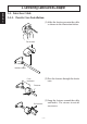
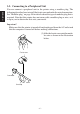
3. Connecting Cables and AC Adapter ENGLISH 3-1. Interface Cable 3-1-1. Ferrite Core Installation (1) Affix the ferrite core onto the cable as shown in the illustration below. Ferrite core Interface cable (2) Pass the fastener through the ferrite core. 5 cm maximum Fastener Pull and cut (3) Loop the fastener around the cable and lock it. Use scissors to cut off any excess.
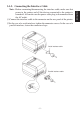
Note: Before connecting/disconnecting the interface cable, make sure that power to the printer and all the devices connected to the printer is turned off. Also make sure the power cable plug is disconnected from the AC outlet. (1) Connect the interface cable to the connector on the rear panel of the printer. (2) In the case of a serial interface, tighten the connector screws. In the case of a parallel interface, fasten the connector clasps.
3-2. Connecting to a Peripheral Unit ENGLISH You can connect a peripheral unit to the printer using a modular plug. The following describes how to install the ferrite core and make the actual connection. See “Modular plug” on page 98 for details about the type of modular plug that is required. Note that this printer does not come with a modular plug or wire, so it is up to you to obtain one that suits your needs.
(2) Pass the fastener through the ferrite core. 5 cm maximum ENGLISH ,,, ,,, Fastener Pull and cut (3) Loop the fastener around the cable and lock it. Use scissors to cut off any excess. (4) Plug one end of the modular cable into the modular jack of the peripheral. (5) Remove the modular jack cover from the back of the printer and plug the other end of the modular cable into the jack of the printer.
3-3. Connecting the Optional AC Adapter ENGLISH Note: Before connecting/disconnecting the AC adapter, make sure that power to the printer and all the devices connected to the printer is turned off. Also make sure the power cable plug is disconnected from the AC outlet. (1) Connect the AC adapter to the power cable. Note: Use only the standard AC adapter and power cable. (2) Connect AC adapter to the connector on the printer. (3) Insert the power cable plug into an AC outlet.
3-4. Turning Power On (1) Set the power switch located on the front of the printer to on. The POWER lamp on the control panel will light up. Power switch Important! We recommend that you unplug the printer from the power outlet whenever you do not plan to use it for long periods. Because of this, you should locate the printer so that the power outlet it is plugged into is nearby and easy to access. –9– ENGLISH Make sure that the AC adapter has been connected as described in 3-3.
4. Control Panel ENGLISH 4-1. PAPER FEED Switch Each time this switch is pressed, the paper feeds on line. When it is kept depressed, the paper feeds continuously. Note: This switch will be ineffective if no paper is loaded. 4-2. POWER LED (green LED) This LED lights up when the power switch is set to on and power is supplied to the printer. 4-3. ERROR LED (red LED) This LED lights up or blinks when any of the following errors occurs.
5-1. Loading New Roll Paper (1) Pull the lever toward you to open the printer cover. Note: Make sure that the lever is pulled until it stops at the stopper. If the lever is not pulled up to the stopper, the printer cover may not open. (2) Peel the adhesive end off the paper. Note: Make sure that the entire adhesive area is removed, since no printing can be performed on that area. (3) Position the paper in the direction as shown below and place it into the paper holder gently.
ENGLISH (4) Make sure that the paper is positioned straight, then close the printer cover gently. Note 1: Make sure that the paper is positioned straight. If the printer cover is closed with the paper skewed as shown below, a paper jam may result. Paper Note 2: Lock the printer cover by pressing on the center of the cover (indicated by an arrow in the figure below). If any part of the cover other than the center is pressed, the cover may not be locked properly. This may sometimes disables printing.
(6) Once the printer cover is locked, the paper end will be ejected and the end cut off automatically. 5-2. Removing Remaining Paper (1) Pull the lever toward you to open the printer cover. Note: Make sure that the lever is pulled until it stops at the stopper. If the lever is not pulled up to the stopper, the printer cover may not open. (2) Remove the remaining paper. – 13 – ENGLISH (5) If the power switch is set to OFF, set it to ON to turn on the printer. Make sure that the ERROR LED is not lit.
6. Near-end Sensor ENGLISH This printer is equipped with a sensor that detects when a roll of paper is near the end. Read the following if you are going to use this sensor. (1) Pull the lever in the direction indicated on it, and then open the printer cover. (2) Loosen the two sensor fixing screws. (3) Slide the sensor unit up or down, and then adequately tighten its screws.
Diameter of remaining paper A Screw position Approx. ø22 mm Level 1 (bottom) Approx. ø26 mm Level 2 (top) Cautions 1) The factory setting is level 1. 2) Always use a paper roll with a core that has an inside diameter of 12 mm and an outside diameter of 18 mm in order to ensure proper detection of the remaining paper amount. – 15 – ENGLISH (4) Insert the paper roll, and check that the sensor correctly detects that the paper roll is about to run out. Error LED LED goes out when there is paper.
7. Preventing and Clearing Paper Jams ENGLISH 7-1. Preventing Paper Jams The paper should not be touched during ejection and before it is cut. Pressing or pulling the paper during ejection may cause a paper jam, paper cutting failure or line feed failure. Do not open the printer cover during cutting. 7-2. Removing Paper Jam If a paper jam occurs, clear it as described below. (1) Set the power switch to off to turn off power to the printer. (2) Pull the lever toward you to open the printer cover.
Note 2: Lock the printer cover by pressing on the center of the cover. If any part of the cover other than the center is pressed, the cover may not be locked properly. This may sometimes disable printing. (5) Set the power switch to on to turn on power to the printer. Make sure that the ERROR LED is not lit. Note: While the ERROR LED is lit, the printer will not accept any commands such as the print command, so make sure that the printer cover is locked properly. 7-3.
ENGLISH (4) If the cutter’s moving blade is protruding, use a Phillips screwdriver to turn the Phillip-head screw and return the moving blade to its home position. When the check window is completely white, the moving blade is at its home position. Note 1: Do not apply extreme pressure to the moving blade. Note 2: If the moving blade is protruding too much, the printer cover cannot be opened. Trying to open the printer cover may damage the cutter.
8-1. Producing a Test Print To start test print, set the power switch to off, set the paper in place, then set the power switch to on while holding down the FEED switch. Release the switch within three seconds. When a certain amount of printing is performed, the printer will cut the paper and stop automatically. 8-2. Hexadecimal Dump This prints data sent from the host in hexadecimal format and in the corresponding ASCII characters.
9. Periodical Cleaning ENGLISH Printed characters may become partially unclear due to accumulated paper dust and dirt. To prevent such a problem, paper dust collected in the paper holder and paper transport section and on the surface of the thermal head must be removed periodically. Such cleaning is recommended to be carried out once a month. 9-1. Cleaning the Thermal Head To remove blackish dust collected on the surface of the thermal head, wipe it with alcohol (IPA).
1. Identification des pièces et nomenclature .................................................... 22 2. Consommables et adaptateur secteur .......................................................... 24 3. Câbles de connexion et adaptateur secteur .................................................25 3-1. Câble d’interface ..................................................................................25 3-2. Raccordement d’un appareil périphérique ........................................... 27 3-3.
1. Identification des pièces et nomenclature Capot de l’imprimante Ouvrez ce capot pour charger ou remplacer le papier. Levier FRANÇAIS Tirez ce levier dans le sens de la flèche pour ouvrir le capot de l’imprimante. Panneau des commandes Le panneau est équipé de commutateurs permettant la commande de l’imprimante et de DELs indiquant les statuts. Connecteur d’alimentation Ce connecteur vous permet de connecter le câble de l’adaptateur secteur.
Emplacement de l’imprimante ✓ Choisissez une surface stable et de niveau sur laquelle l’imprimante ne sera exposée à aucune vibration. ✓ Assurez-vous que l’emplacement dispose d’une prise secteur proche et d’accès aisé. ✓ Assurez-vous que la distance entre l’imprimante et l’ordinateur-hôte vous permet de les raccorder aisément. ✓ Assurez-vous que l’imprimante n’est pas exposée directement aux rayons du soleil.
2. Consommables et adaptateur secteur FRANÇAIS Il convient d’utiliser exclusivement les types de papier figurant dans le tableau ci-dessous. Veillez également à utiliser l’adaptateur secteur qui figure dans le tableau. L’utilisation d’un type de papier et d’adaptateur ne figurant pas dans le tableau risque d’endommager l’imprimante, de causer un incendie ou une décharge électrique.
3. Câbles de connexion et adaptateur secteur 3-1. Câble d’interface (1) Fixez le tore de ferrite sur le câble comme illustré. Tore de ferrite Interface câble 5 cm maximum (2) Passez l’attache dans le tore de ferrite. Attache Tirez et coupez (3) Passez l’attache autour du tore de ferrite et serrez-la. Coupez l’extrémité de l’attache à l’aide de ciseaux. – 25 – FRANÇAIS 3-1-1.
3-1-2. Connexion du câble d’interface Remarque:Avant de connecter ou déconnecter le câble d’interface, veillez à ce que l’imprimante et tous les appareils qui y sont connectés soient hors tension. Veillez également à débrancher le câble d’alimentation de la prise secteur. FRANÇAIS (1) Connectez le câble d’interface à la borne figurant sur le panneau arrière de l’imprimante. (2) Dans le cas d’une interface série, resserrez les vis du connecteur.
Vous pouvez raccorder un appareil périphérique à l’imprimante à l’aide d’une fiche modulaire. Nous expliquons ci-dessous comment installer le tore de ferrite et faire le raccordement proprement dit. Pour les détails sur le type de fiche modulaire à utiliser, reportez-vous à la page 98. Notez que le fil ou la fiche modulaires ne sont pas fournis avec l’imprimante. Vous devrez donc vous les procurer.
5 cm maximum ,,, ,,, Attache FRANÇAIS Tirez et coupez (3) Passez l’attache autour du tore de ferrite et serrez-la. Coupez l’extrémité de l’attache à l’aide de ciseaux. (4) Raccordez une extrémité du câble modulaire à la prise modulaire du périphérique. (5) Retirez le cache de prise modulaire au dos de l’imprimante, et raccordez l’autre extrémité du câble modulaire dans la prise de l’imprimante.
3-3. Connexion de l’adaptateur secteur optionnel (1) Connectez l’adaptateur secteur au câble d’alimentation. Remarque:Utilisez exclusivement l’adaptateur secteur et le câble d’alimentation destinés à l’imprimante. (2) Connectez l’adaptateur secteur à la borne de l’imprimante. (3) Branchez la prise du câble d’alimentation à la prise secteur.
3-4. Mise sous tension de l’imprimante Assurez-vous d’avoir bien connecté l’adaptateur secteur comme décrit à la section 3-3. FRANÇAIS (1) Placez l’interrupteur d’alimentation, situé à l’avant de l’imprimante, sur la position sous tension. La DEL POWER s’allume au panneau des commandes. Interrupteur d’alimentation Attention! Nous vous recommandons de débrancher l’imprimarte du secteur lorsque vous ne comptez pas l’utiliser pendant une période prolongée.
4. Panneau des commandes Le papier avance d’une ligne à chaque pression sur cette touche. Une pression continue sur la touche fera avancer le papier de façon continue. Remarque:Une pression sur cette touche n’a d’effet que si du papier est chargé dans l’imprimante. 4-2. DEL d’alimentation POWER (DEL verte) Cette DEL s’allume lorsque l’interrupteur d’alimentation est placé sur hors tension et que l’appareil est alimenté par le secteur. 4-3.
5. Chargement du papier 5-1. Chargement d’un rouleau de papier neuf FRANÇAIS (1) Tirez le levier vers le bas afin d’ouvrir le capot de l’imprimante. Remarque:Veillez à tirer le levier tout à fait jusqu’à sa butée. Si le levier n’est pas tiré tout à fait, le capot pourrait ne pas s’ouvrir. (2) Retirez l’adhésif de l’extrémité du papier. Remarque:Veillez à bien retirer l’intégralité de l’adhésif. En effet, l’impression ne peut s’effectuer sur celui-ci.
FRANÇAIS (4) Veillez à ce que le papier soit placé bien droit, puis refermez doucement le capot de l’imprimante. Remarque 1: Le papier doit être placé bien droit. Si vous refermez le capot de l’imprimante alors que le papier est de travers (voir illustration), un bourrage peut se produire. Papier Remarque 2: Verrouillez le cache de l’imprimante en appuyant à l’endroit du capot repéré par la flèche dans l’illustration ci-dessous.
(5) Si l’interrupteur d’alimentation est sur la position hors tension OFF, réglezle sur la position sous tension ON pour mettre l’imprimante sous tension. Assurez-vous que la DEL ERROR n’est pas allumée. Remarque:Tant que la DEL ERROR est allumée, l’imprimante n’accepte aucune commande. Il faut donc veiller à ce que le capot de l’imprimante soit verrouillé. FRANÇAIS (6) Une fois que le capot d’imprimante est verrouillé, l’extrémité du papier sera éjectée et coupée automatiquement. 5-2.
6. Capteur de fin de rouleau (1) Tirez sur le levier dans le sens indiqué dessus, puis ouvrez le capot de l’imprimante. (2) Desserrez les deux vis de montage du capteur. (3) Faites glisser le capteur vers le haut ou vers le bas, puis serrez correctement ses vis. Le tableau suivant indique le diamètre du papier devant rester sur le rouleau afin que le capteur installé dans la position spécifiée de la vis de montage du capteur puisse le détecter.
(4) Insérez le rouleau de papier, puis vérifiez que le capteur identifie correctement le moment où le papier va être épuisé. DEL d’erreur La DEL s’éteint quand il y a du papier. La DEL clignote quand le papier va être épuisé. FRANÇAIS Diamètre du papier restant A Position de la vis Environ ø22 mm Cran 1 (bas) Environ ø26 mm Cran 2 (haut) Attention 1) Le capteur de fin de rouleau est positionné sur le cran 1 à la sortie d’usine.
7. Prévention et correction de bourrages de papier Il convient de ne jamais toucher le papier pendant son éjection et avant qu’il soit coupé. Appuyer ou tirer sur le papier pendant son éjection risque de provoquer un bourrage, des problèmes de coupure ou d’avance de ligne. Ne pas ouvrir le capot d’imprimante pendant la coupure. 7-2. Correction de bourrages de papier En cas de bourrage de papier, procédez comme suit afin d’y remédier : (1) Mettez l’appareil hors tension.
(4) Veillez à insérer le rouleau de papier tout droit et refermez avec soin le capot de l’imprimante. Remarque 1: Le papier doit être placé bien droit. Si vous refermez le capot de l’imprimante alors que le papier est de travers (voir illustration), un bourrage peut se produire. Remarque 2: FRANÇAIS Verrouillez le cache de l’imprimante en appuyant à l’endroit du capot repéré par la flèche dans l’illustration ci-dessous.
Unité de découpage automatique FRANÇAIS Couvercle avant (4) Si la lame mobile de l’unité de découpage dépasse, utilisez un tournevis cruciforme pour tourner la vis cruciforme et ramener la lame dans sa position d’origine. Quand la fenêtre de contrôle est complètement blanche, la lame mobile est dans sa position d’origine. Remarque 1: N’appliquez pas de pression excessive sur la lame mobile. Remarque 2: Si la lame mobile dépasse trop, le capot de l’imprimante ne pourra pas être ouvert.
8. Test d’impression 8-1. Exécution d’un test d’impression FRANÇAIS Avant d’effectuer un test d’impression, commencez par mettre l’imprimante hors tension, insérez le papier, puis remettez l’imprimante sous tension tout en maintenant la touche d’avance FEED enfoncée. Relâchez la pression sur la touche dans les trois secondes qui suivent. Après avoir imprimé pendant un certain temps, l’imprimante coupe le papier et s’arrête automatiquement. 8-2.
Les caractères imprimés pourraient devenir partiellement illisibles en raison de l’accumulation de la poussière de papier et de crasse. Afin de prévenir ce genre de problème, il convient de nettoyer régulièrement la poussière qui s’accumule sur le support de papier, les passages du papier et la surface de la tête d’impression. Il est recommandé d’effectuer ce nettoyage une fois par mois. 9-1.
FRANÇAIS – 42 –
1. Beschreibung und Bezeichnung der Geräteteile ......................................... 44 2. Verbrauchsteile und Netzteil ........................................................................ 46 3. Anschlußkabel und Netzteil ..........................................................................47 3-1. Schnittstellenkabel ............................................................................... 47 3-2. Anschluß an ein Peripheriegerät ..........................................................
1. Beschreibung und Bezeichnung der Geräteteile Abdeckung Diese Abdeckung öffnen, um Papier einzusetzen oder zu entnehmen. Hebel Diesen Hebel in Pfeilrichtung ziehen, um die Druckerabdeckung zu öffnen. DEUTSCH Bedienfeld Mit LED-Anzeigen zur Anzeige des Druckerstatus und Schalter zur Druckerbedienung. Schalter Zum Ein- oder Ausschalten des Druckers. Betriebsstromanschluß Peripherie-Treiberanschluß Zum Anschließen des Betriebsstromkabels vom Netzteil.
Wahl eines Aufstellungsorts für den Drucker ✓ Den Drucker auf einem flachen, aber festen Untergrund aufstellen, wo keine Vibrationen vorhanden sind. ✓ Die verwendete Steckdose soll in der Nähe und frei zugänglich sein. ✓ Sicherstellen, daß der Drucker nahe genug am Computer ist, um die Geräte mit dem Druckerkabel verbinden zu können. ✓ Sicherstellen, daß der Drucker vor direktem Sonnenlicht geschützt ist. ✓ Sicherstellen, daß der Drucker ausreichend weit von Heizkörpern entfernt steht.
2. Verbrauchsteile und Netzteil Wenn die Verbrauchsteile verbraucht sind, besorgen Sie Ersatz entsprechend der unten gezeigten Tabelle. Verwendung von Verbrauchsteilen oder Netzteilen, die nicht den unten aufgeführten Beschreibungen entsprechend, kann zu Schäden am Drucker, Bränden oder elektrischen Schlägen führen.
3. Anschlußkabel und Netzteil 3-1. Schnittstellenkabel 3-1-1. Anbringen des Ferritkerns DEUTSCH (1) Befestigen Sie den Ferritkern am Kabel, wie das in der folgenden Abbildung gezeigt wird. Ferritkern Kable (2) Führen Sie den Kabelbinder durch den Ferritkern. Maximum 5 cm Kabelbinder Ziehen und abschneiden (3) Führen Sie den Kabelbinder um das Kabel und sperren Sie ihn. Schneiden Sie überschüssiges Band mit einer Schere ab.
3-1-2. Anschließen des Schnittstellenkabels Hinweis:Vor dem Anschließen/Abtrennen des Schnittstellenkabels stellen Sie sicher, daß der Drucker und alle angeschlossenen Gerät ausgeschaltet sind. Außerdem sollte der Netzstecker abgezogen sein. (1) Schließen Sie das Schnittstellenkabel an die Buchse an der Rückseite des Druckers an. (2) Bei einer seriellen Schnittstelle ziehen Sie die Steckerschrauben fest. Bei einer parallelen Schnittstelle befestigen Sie die Steckerklammern.
3-2. Anschluß an ein Peripheriegerät Es kann ein Peripheriegerät an den Drucker mit einem Modularstecker angeschlossen werden. Im folgenden wird beschrieben, wie der Ferritkern angebracht und die Verbindung hergestellt wird. Siehe “Modularstecker” auf Seite 98 für den Typ von Modularstecker, der dazu erforderlich ist. Beachten Sie, daß der Drucker nicht mit einem Modularstecker oder Kabel ausgestattet ist. Diese Teile müssen vom Anwender besorgt werden.
(2) Den Kabelbinder durch den Ferritkern führen. Maximum 5 cm ,,, ,,, Kabelbinder Ziehen und abschneiden DEUTSCH (3) Das Befestigungsband um das Kabel wickeln und sperren. Schneiden Sie überschüssiges Band mit einer Schere ab. (4) Einen Stecker des Modularkabels in die Modularbuchse am Peripheriegerät stecken. (5) Die Modularbuchsenabdeckung von der Rückseite des Druckers abnehmen, und den anderen Stecker des Modularkabels in die Modularbuchse am Drucker stecken.
3-3. Anschließen des optionalen Netzteils Hinweis:Vor dem Anschließen/Abtrennen des Netzteils stellen Sie sicher, daß der Drucker und alle angeschlossenen Gerät ausgeschaltet sind. Außerdem sollte der Netzstecker abgezogen sein. (1) Schließen Sie das Netzteil an das Netzkabel an. Hinweis:Verwenden Sie nur das vorgesehene Netzteil und Netzkabel. (2) Das Netzteil am Stecker des Druckers anschließen. DEUTSCH (3) Stecken Sie den Netzstecker des Netzteils in eine Steckdose ein.
3-4. Einschalten Stellen Sie sicher, daß das Netzteil angeschlossen ist, wie in 3-3 beschrieben. (1) Den Netzschalter vorne am Gerät auf Ein (ON) stellen. Das POWERLämpchen am Bedienfeld leuchtet auf. DEUTSCH Netzschalter Wichtig! Wir empfehlen, den Netzstecker aus der Steckdose zu ziehen, wenn der Drucker längere Zeit lang nicht benutzt werden soll. Der Drucker sollte vorzugsweise an einem Platz aufgestellt werden, der leichten Zugang zur Netzsteckdose gewährt.
4. Bedienfeld 4-1. Papiereinzugknopf (PAPER FEED) Bei jedem Drücken dieses Knopfes wird das Papier um eine Zeile vorgeschoben. Wenn der Knopf gedrückt gehalten wird, wird das Papier kontinuierlich vorgeschoben. Hinweis:Dieser Knopf ist unwirksam, wenn kein Papier eingelegt ist. Diese LED leuchtet auf, wenn der Netzschalter in Ein-Stellung ist und Betriebsstrom am Drucker anliegt. 4-3. Fehler-LED (ERROR) (rote LED) Diese LED leuchtet oder blinkt, wenn einer der folgenden Fehler auftritt.
5. Einlegen von Papier 5-1. Einlegen einer neuen Papierrolle DEUTSCH (1) Ziehen Sie den Hebel nach vorne, um die Druckerabdeckung zu öffnen. Hinweis:Stellen Sie sicher, daß der Hebel gezogen wird, bis er am Anschlag stoppt. Wenn der Hebel nicht bis zum Anschlag gezogen wird, kann es sein, daß sich die Druckerabdeckung nicht öffnen läßt. (2) Das Klebestück am Papierende abziehen. Hinweis:Stellen Sie sicher, daß der gesamte Klebebereich entfernt ist, da in diesem Bereich nicht gedruckt werden kann.
DEUTSCH (4) Stellen Sie sicher, daß das Papier gerade ausgerichtet ist, und schließen Sie die Druckerabdeckung vorsichtig. Hinweis 1: Stellen Sie sicher, daß das Papier gerade ausgerichtet ist. Wenn die Druckerabdeckung bei schief liegendem Papier geschlossen wird, wie unten gezeigt, kann ein Papierstau auftreten. Papier Hinweis 2: Sperren Sie die Druckerabdeckung durch Drücken auf die Mitte der Abdeckung (in der Abbildung unten durch einen Pfeil gekennzeichnet).
(5) Wenn der Netzschalter auf Aus (OFF) gestellt ist, auf Ein (ON) stellen, um den Drucker einzuschalten. Stellen Sie sicher, daß die ERROR-LED nicht leuchtet. Hinweis:Während die ERROR-LED leuchtet, akzeptiert der Drucker keine Befehle wie Druckbefehl; stellen Sie deshalb sicher, daß die Abdeckung richtig geschlossen ist. (6) Wenn die Druckerabdeckung verriegelt ist, wird das Papierende ausgegeben, und das Ende automatisch abgeschnitten. 5-2.
6. Papiervorrat-Sensor Der Drucker ist mit einem Sensor ausgestattet, der erkennt, wenn das Ende einer Papierrolle fast erreicht ist. Zum Einsatz dieses Sensors wie folgt verfahren. (1) Den Hebel in der angezeigten Richtung ziehen, und dann die Druckerabdeckung öffnen. (3) Die Sensoreinheit nach oben oder unten schieben, und dann die Schrauben richtig festziehen.
(4) Die Papierrolle einsetzen, und prüfen ob der Sensor richtig erkennt, daß das Papier fast verbraucht ist. Fehler-LED Die LED geht aus, wenn Papier vorhanden ist. Die LED blinkt, wenn das Papier fast verbraucht ist. Durchmesser des verbleibenden Papiers A Schraubenposition Ca. ø22 mm Position 1 (unten) Ca. ø26 mm Position 2 (oben) DEUTSCH Vorsichtsmaßregeln 1) Die werksseitige Einstellung ist Position 1.
7. Verhindern und Beheben von Papierstau 7-1. Verhindern von Papierstau DEUTSCH Das Papier soll beim Ausgeben und vor dem Schneiden nicht berührt werden. Wenn das Papier beim Ausgeben gedrückt oder gezogen wird, kann ein Papierstau, ein Abschneidfehler oder ein Zeilenvorschubfehler verursacht werden. Nicht die Druckerabdeckung während des Abschneidensöffnen. 7-2. Beheben von Papierstau Wenn ein Papierstau auftritt, beheben Sie ihn wie folgt.
(4) Stellen Sie sicher, daß das Papier gerade ausgerichtet ist, und schließen Sie die Druckerabdeckung vorsichtig. Hinweis 1: Stellen Sie sicher, daß das Papier gerade ausgerichtet ist. Wenn die Druckerabdeckung bei schief liegendem Papier geschlossen wird, kann ein Papierstau auftreten. Hinweis 2: Sperren Sie die Druckerabdeckung durch Drücken auf die Mitte der Abdeckung. Wenn ein anderer Teil der Abdeckung als die Mitte gedrückt wird, kann die Abdeckung nicht richtig geschlossen werden. Dadurch kann u.U.
Automatisches Schneidmesser (4) Wenn die bewegliche Klinge des Schneidmessers hervorsteht, mit einem Kreuzschlitzschraubenzieher die Kreuzschlitzschraube drehen, und die bewegliche Klinge in Grundstellung zurückstellen. Wenn das Prüffenster vollständig weiß ist, ist die bewegliche Klinge in Grundstellung. Hinweis 1: Nicht starken Druck auf die bewegliche Klinge ausüben. Hinweis 2: Wenn die bewegliche Klinge zu sehr hervorsteht, kann die Druckerabdeckung nicht geöffnet werden.
8. Testdruck-Verfahren 8-1. Erstellen eines Testdrucks Zum Starten des Testdrucks schalten Sie den Drucker mit dem Netzschalter aus, setzen das Papier richtig ein, und schalten dann den Drucker bei gedrückt gehaltener FEED-Knopf ein. Den Schalter innerhalb von drei Sekundenfreigeben. Der Testdruck stoppt automatisch nach dem Ausdruck der vorgegebenen Druckmenge, und der Drucker schneidet das Papier ab. 8-2.
9. Regelmäßige Reinigung Die Druckzeichen können durch Ansammlung von Papierstaub und anderem Schmutz unscharf werden. Um das zu verhindern, muß im Papierhalter und in der Papiertransportstufe angesammelter Staub von Zeit zu Zeit entfernt werden. Eine derartige Reinigung sollte etwa einmal im Monat ausgeführt werden. Zum Entfernen von schwärzlichem Staub auf der Oberfläche des Thermalkopfes diesen mit Isopropylalkohol (IPA) abwischen. Hinweis:Der Thermalkopf läßt sich leicht beschädigen.
DEUTSCH – 64 –
1. Identificazione delle parti e nomenclatura .................................................. 66 2. Parti soggette a consumo e trasformatore CA ............................................ 68 3. Cavi di collegamento e trasformatore CA ................................................... 69 3-1. Cavo interfaccia ................................................................................... 69 3-2. Collegamento ad un’unità periferica .................................................... 71 3-3.
1. Identificazione delle parti e nomenclatura Coperchio stampante Aprire questo coperchio per inserire o sostituire la carta. Leva Tirare questa leva in direzione della freccia per aprire il coperchio della stampante. Pannello di controllo Dispone di indicatori LED che indicano lo stato della stampante e di interruttori per controllare la stampante. Interruttore Usarlo per accendere/ spegnere la stampante.
Scelta di un luogo per la stampante ✓ Scegliere una superficie stabile e in piano, dove la stampante non sia esposta a vibrazioni. ✓ La presa di corrente che si intende usare per la stampante deve essere vicina e libera da ostacoli. ✓ La stampante deve essere abbastanza vicina al computer da permettere il collegamento tra i due. ✓ Assicurarsi che la stampante non sia esposta alla luce solare diretta. ✓ Assicurarsi che la stampante sia lontana da caloriferi e altre fonti di calore elevato.
2. Parti soggette a consumo e trasformatore CA Quando le parti soggette a consumo si sono esaurite, usare quelle specificate nella seguente tabella. Assicurarsi di usare il trasformatore CA specificato nella tabella. L’uso di parti soggette a consumo o di un trasformatore CA diversi da quanto specificato nella tabella può causare danni alla stampante, incendi o scosse elettriche.
3. Cavi di collegamento e trasformatore CA 3-1. Cavo interfaccia 3-1-1. Installazione dell’anello di ferrite (1) Fissare l’anello di ferrite al cavo come mostrato nell’illustrazione qui sotto. ITALIANO Anello di ferrite Cavo 5 cm massimo (2) Far passare la fascetta di fissaggio attraverso l’anello di ferrite. Fascetta di fissaggio Tirare e tagliare (3) Avvolgere la fascetta intorno al cavo e fissarla. Usare delle forbici per tagliare la parte in eccesso.
3-1-2. Collegamento del cavo interfaccia Nota: Prima di collegare/scollegare il cavo interfaccia, assicurarsi che la stampante e tutti i dispositivi collegati alla stampante siano spenti. Inoltre assicurarsi che la spina del cavo di alimentazione sia scollegata dalla presa di corrente. (1) Collegare il cavo interfaccia al connettore sul pannello posteriore della stampante. (2) Nel caso di un interfaccia seriale, serrare le viti del connettore.
3-2. Collegamento ad un’unità periferica Si può collegare un’unità periferica alla stampante usando una spina modulare. Di seguito descriviamo come installare l’anello di ferrite ed eseguire il collegamento. Vedere “Modulare necessario” a pagina 98 per dettagli sul tipo di spina modulare necessario. Notare che la stampante non è dotata di spina o filo modulare, che devono essere acquistati in base alle esigenze di impiego.
(2) Far passare la fascetta di fissaggio attraverso l’anello di ferrite. 5 cm massimo ,,, ,,, Fascetta di fissaggio Tirare e tagliare ITALIANO (3) Avvolgere la fascetta intorno al cavo e fissarla. Usare delle forbici per tagliare la parte in eccesso. (4) Collegare un capo del cavo modulare alla presa modulare della periferica. (5) Rimuovere il coperchio presa modulare dal retro della stampante e collegare l’altro capo del cavo modulare alla presa sulla stampante.
3-3. Collegamento del trasformatore CA opzionale Nota: Prima di collegare/scollegare il trasformatore CA, assicurarsi che la stampante e tutti i dispositivi collegati alla stampante siano spenti. Inoltre assicurarsi che la spina del cavo di alimentazione sia scollegata dalla presa di corrente. (1) Collegare il trasformatore CA al cavo di alimentazione. Nota: Usare solo il trasformatore CA e cavo di alimentazione standard. (2) Collegare il trasformatore CA al connettore sulla stampante.
3-4. Accensione Assicurarsi che il trasformatore CA sia stato collegato come indicato nella sezione 3-3. (1) Regolare su ON l’interruttore di alimentazione situato sul davanti della stampante. La spia POWER sul pannello di controllo si illumina. ITALIANO Interruttore di alimentazione Importante! Consigliamo di scollegare la stampante dalla presa di corrente quando si prevede di non usarla per un lungo periodo.
4. Pannello di controllo 4-1. Interruttore PAPER FEED A ciascuna pressione di questo interruttore la carta avanza di una riga. Se si tiene premuto l’interruttore, la carta avanza continuamente. Nota: Questo interruttore non funziona se non è inserita carta. 4-2. Spia POWER (LED verde) Questa spia a LED si illumina quando l’interruttore di alimentazione è attivato e la stampante riceve alimentazione. 4-3.
5. Caricamento della carta 5-1. Caricamento di un nuovo rotolo di carta (1) Tirare la leva verso di sè per aprire il coperchio stampante. Nota: Assicurarsi di tirare la leva fino a che si arresta al fermo. Se la leva non viene tirata fino al fermo, il coperchio stampante può non aprirsi. (2) Togliere l’adesivo dall’estremità della carta. Nota: Assicurarsi di rimuovere completamente la parte adesiva, perché la stampa non può essere eseguita su quella parte.
ITALIANO (4) Assicurarsi che la carta sia collocata ben diritta e quindi chiudere delicatamente il coperchio stampante. Nota 1: Assicurarsi che la carta sia ben diritta. Se si chiude il coperchio stampante con la carta storta come mostrato sotto, si può verificare un inceppamento della carta. Carta Nota 2: Bloccare il coperchio della stampante premendo sul centro del coperchio (indicato dalla freccia nella figura sotto).
(5) Se l’interruttore di alimentazione è regolato su OFF, regolarlo su ON per accendere la stampante. Assicurarsi che la spia ERROR non sia illuminata. Nota: Mentre la spia ERROR è illuminata, la stampante non accetta alcun comando come il comando di stampa, per cui assicurarsi che il coperchio della stampante sia bloccato correttamente. (6) Una volta che il coperchio stampante è stato bloccato, l’estremità della carta fuoriesce e viene tagliata automaticamente. 5-2.
6. Sensore di rilevamento fine carta Questa stampante è dotata di un sensore in grado di rilevare quando un rotolo di carta sta per terminare. Leggere le seguenti istruzioni se si intende utilizzare questa funzione. (1) Tirare la leva nella direzione indicata su di essa e quindi aprire il coperchio della stampante. (2) Allentare le due viti di fissaggio del sensore. ITALIANO (3) Spostare l’unità sensore in alto o in basso e quindi serrare bene le sue viti.
(4) Inserire il rotolo di carta e controllare che il sensore rilevi correttamente che il rotolo sta per finire. LED di errore Il LED non sia illuminata quando c’è carta. Il LED lampeggia quando la carta è quasi esaurita. Diametro della carta rimanente A Posizione vite Circa ø22 mm Posizione 1 (fondo) Circa ø26 mm Posizione 2 (cima) Attenzione 1) L’impostazione di fabbrica è la posizione 1.
7. Prevenzione e soluzione degli inceppamenti della carta 7-1. Prevenzione degli inceppamenti della carta ITALIANO La carta non deve essere toccata durante l’espulsione e prima che sia tagliata. Se si preme o si tira la carta durante l’espulsione si può verificare un inceppamento della carta, un mancato taglio della carta o un avanzamento di riga mancato. Non aprire il coperchio stampante durante il taglio. 7-2.
(4) Collocare diritto il rotolo di carta e chiudere delicatamente il coperchio stampante. Nota 1: Assicurarsi che la carta sia ben diritta. Se si chiude il coperchio stampante con la carta storta, si può verificare un inceppamento della carta. Nota 2: Bloccare il coperchio della stampante premendo sul centro del coperchio. Se si preme una parte del coperchio diversa dal centro, il coperchio può non bloccarsi correttamente. Questo a volte rende impossibile la stampa.
Taglierina automatica (4) Se la lama mobile della taglierina sporge, usare un cacciavite Philips per girare la vite a testa Philips e riportare la lama mobile alla sua posizione di partenza. Quando la finestrella di controllo appare completamente bianca, la lama mobile è nella sua posizione di partenza. Nota 1: Non applicare estrema pressione alla lama mobile. Nota 2: Se la lama mobile sporge eccessivamente, non è possibile aprire il coperchio stampante.
8. Metodo per la stampa di prova 8-1. Produzione di uno stampato di prova Per avviare la stampa di prova, regolare su OFF l’interruttore di alimentazione, inserire la carta e quindi regolare l’interruttore di alimentazione su ON tenendo premuto il interruttore FEED. Rilasciare l’interruttore entro tre secondi. Quando è stato eseguita una certa quantità di stampa, la stampante taglia la carta e si ferma automaticamente. 8-2.
9. Pulizia periodica I caratteri stampati possono diventare parzialmente poco chiari a causa dell’accumulo di polvere di carta e sporcizia. Per evitare tale problema, è necessario rimuovere periodicamente la polvere di carta accumulata nel comparto carta, nella sezione di trasporto carta e sulla superficie della testina termica. Si consiglia di eseguire questa pulizia una volta al mese. 9-1. Pulizia della testina termica 9-2.
ITALIANO – 86 –
Appendix A: Specifications (1) Printing method Direct line thermal printing (2) Print speed Max. 75 mm/s (3) Dot density 203 dpi: 8 dots/mm (0.125 mm/dot) (4) Number of print columns 48 (12 × 24 dots) 64 (9 × 24 dots): ESC/POS mode only (5) Roll paper Refer to chapter 2 for details on the recommended roll paper. Paper width: 80- 01.0 mm Roll diameter: ø90 mm or less External diameter of core: ø18 +0.5 0 mm Internal diameter of core: ø12 ± 0.
A-2. Print Specifications (1) Print width (2) Character size (3) Character structure (4) Character set 72 mm (576 dots) Front A: 1.50 × 3.00 mm Front B (ESC/POS mode only): 1.13 × 3.00 mm Front A: 12 × 24 dots Front B (ESC/POS mode only): 9 × 24 dots ASCII: 96 Extended graphics: 128 × 8 International: 32 A-3. Auto Cutter Specifications (1) Partial cut (2) Cutting frequency (3) Thickness of paper Cutting with one point left uncut Max. 30 cuts per minute Max. 0.08 mm A-4.
Important! • When using a printer power supply other than the optional AC adaptor (UP06021240), be sure that the following cautions are observed. • Use a power supply of DC 24 V ±5% and more than 2.5 A. • Be careful about installing the printer in an area where there is noise. Take the appropriate measures to protect against electrostatic AC line noise, etc. A-6.
Appendix B: Dip Switch Setting Two DIP switches are provided at the bottom of the printer, and can be set as given in the table below. Be sure to set the power switch to off before changing the settings. It is recommended to use a pointed item like a pen or flat-blade driver screw to change the settings. The settings will become effective when the power switch is set to on again. The following is the procedure for changing the settings on DIP switches. 1. Make sure the printer is turned off. 2.
B-1. Serial Interface Type ON ON OFF No. 1 2 3 4 5 6 7 8 OFF No. 1 2 3 4 5 6 7 8 DIP-SW1 DIP-SW1 DIP-SW 1 Switch Function ON OFF 1 Data receive error Error is ignored. 2 Receive buffer size 68 bytes “?” is printed.
B-2. Parallel Interface Type ON ON OFF OFF No. 1 2 3 4 5 6 7 8 No.
Appendix C: Parallel Interface The two-way parallel interface is compatible with the IEEE1284 compatibility mode, nibble mode and byte mode. Refer to the separate programmer’s manual for details. C-1.
31 In Compatibility Mode Signal Name INT IN 32 Out ERROR OUT DATAAV/DATA0.4 *1 DATAAV GND GND GND 34 Out DKSTS — — 35 Out Logic H Logic H Logic H 36 In SELECT IN 1284 Active *1 1284 Active *1 Pin No.
C-2. Function for Compatibility Mode Pin No. Signal Name IN/OUT Function 1 STB IN Signals when data is ready to be read. Signal goes from HIGH to LOW (for at least 0.5 microsec.) when the data is available. 2-9 DATA0-7 IN These signals provide the information of the first to eighth bits of parallel data. Each signal is at HIGH level for a logical 1 and at a LOW level for a logical 0. 10 ACK OUT OUT LOW pulse acknowledges receipt of the data.
Appendix D: Serial Interface D-1. RS-232C Connector 1 Signal name FG Frame ground 14 Signal name – 2 TXD Send data OUT 15 – 3 RXD Receive data IN 16 – 4 RTS Request to send OUT 17 – 5 – 18 – 6 DSR Data set ready 7 SG Signal GND 8 9 Pin No. I/O direction Function Pin No.
D-2. Cable Connections The followings are a recommended interface cable connections. Printer side (D-sub 25 pin) Host side 25 pin 9 pin FG 1 1 TXD 2 2 3 TXD RXD 3 3 2 RXD RTS 4 4 7 RTS 5 8 CTS DSR 6 6 6 DSR SG 7 7 5 SG DTR 20 8 1 DCD INIT 25 20 4 DTR D-3. Electrical Characteristics Voltage Data signal Control signal Binary status -3V to -15V Mark OFF 1 +3V to +15V Space ON 0 – 97 – APPENDIX Note Use shielded wire less than 3m in length.
Appendix E: Periheral Unit Drive Circuit E-1. Peripheral Drive Connector 1 Signal name FG Frame ground 2 DRD1 Drive signal 1 OUT 3 +24V Drive power OUT Pin No. Function I/O direction — 4 +24V Drive power OUT 5 DRD2 Drive signal 2 OUT 6 DRSNS Sense signal IN 6 1 Modular plug Modular plug: MOLEX 90075-0007, AMP641337, or JAPAN BURNDY B-66-4 Shield APPENDIX 1 6 Wire lead Notes 1. A shield cable must be used. 2.
ELECTRONIC PRODUCTS DIVISION STAR MICRONICS CO., LTD. OVERSEAS SUBSIDIARY COMPANIES STAR MICRONICS AMERICA, INC. 536 Nanatsushinnya, Shimizu, Shizuoka, 424-0066 Japan Tel: 0543-47-0112, Fax: 0543-48-5013 1150 King Georges Post Road, Edison, NJ 08837-3729 U.S.A. Tel: 732-623-5555, Fax: 732-623-5590 Please access the following URL http://www.star-micronics.co.jp/service/frame_sp_spr_e.htm for the lastest revision of the manual. STAR MICRONICS U.K. LTD.