THERMAL PRINTER TSP400Z SERIES USER’S MANUAL MODE D’EMPLOI BEDIENUNGSANLEITUNG MANUALE DI ISTRUZIONI
Federal Communications Commission Radio Frequency Interference Statement This equipment has been tested and found to comply with the limits for a Class A digital device, pursuant to Part 15 of the FCC Rules. These limits are designed to provide reasonable protection against harmful interference when the equipment is operated in a commercial environment.
TABLE OF CONTENTS 1. UNPACKING AND INSPECTION ...................................................... 1 1-1. Unpacking .................................................................................... 1 1-2. Handling Notes ............................................................................ 1 2. PARTS IDENTIFICATION AND NOMENCLATURE ...................... 2 3. FERRITE CORE INSTALLATION *EUROPE ONLY ...................... 3 3-1. Parallel interface ...................................................
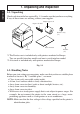
1. Unpacking and inspection ENGLISH 1-1. Unpacking Check each item in the box against Fig. 1-1 to make sure that you have everything. If any of these items are missing, contact your supplier. Sample paper roll Paper-roll shaft Ferrite core(s) (*1) User’s manual Printer ,, Fastener (*2) *1 The Ferrite core is included only with printers marketed in Europe. Two are parallel interface models and one is serial interface model. *2 A fastener is included only with printers marketed in Europe. Fig. 1-1 1-2.
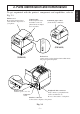
To get acquainted with the printer’s components and capabilities, refer to Fig. 2-1. Printer cover Protects the print head and other internal components of your printer. Control panel Indicates printer status and makes control of printer functions simple and convenient. Automatic paper cutter (Controlled by command) POWER HEAD UP NO PAPER ERROR (TSP442Z) ON LINE FEED Release bar Opens and closes the print head unit which holds the paper against the platen.
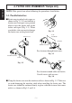
3. Ferrite core installation *Europe only ENGLISH NOTE: Take special care when following the procedures listed below. 3-1. Parallel interface ■ Ferrite core is packed so it is open, as shown in Fig. 3-2. If you find that a ferrite core is not open, use a pointed object to pry the plastic lock of the ferrite core apart (Fig. 3-1). When you do this, take care not to damage the ferrite core or the plastic lock. Fig.
■ Clamp the ferrite core onto the cable of the peripheral unit using the same procedure as you do for the parallel interface cable ferrite core. With the peripheral unit cable ferrite core, however, you have to loop the cable as shown in Fig. 3-5. NOTE: The ferrite cores only need to be attached for the European region (only printers marketed in Europe are eligible.) Install both the parallel interface model and the serial interface model. 5 cm or less Ferrite core Ground wire Fig.
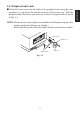
4. Connecting the interface cable ENGLISH 4-1. Serial interface Follow the procedures below to connect the interface cable: 1 Switch off the power to the printer and computer. 2 Insert the interface cable in the connector. (Be sure that the cable is oriented correctly before inserting it.) Interface cable Interface connector 3 Fasten the right and left screws to fix them in place on the connector. 4 Connect the other end of the interface cable to your computer. Fig.
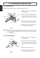
■ First, remove the blue semi-transparent tape from all parts. ■ Before loading the first paper roll, be sure to remove the cardboard and the protective paper (under the tear bar) that were inserted to protect the print head during shipping. Fig. 5-1 5-1. Loading the Paper Roll The procedure for loading a paper roll is as follows. The illustrations show the TSP412Z printer. However, the loading procedure for the TSP442Z is the same. Printer cover 1 Switch off the printer’s power. 2 Open the printer cover.
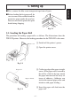
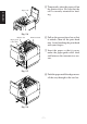
5 Temporarily place the paper roll on the printer cover. Be sure that the roll is correctly oriented for loading. Paper roll ENGLISH Fig. 5-4 Release bar Paper guide roller shaft Print head unit 6 Pull on the green release bar so that it unlocks, then tilt the print head unit. Avoid touching the print head with your fingers. 7 Insert the paper so that it passes under the paper-guide roller shaft and between the transmissive sensors. Fig.
0 Move the paper roll onto the printer’s paper-roll holder. A Hold the roll down and pull on the leading edge of the paper to remove any slack. Fig. 5-7 B Close the printer cover. 5-2. Adjusting the Head Position 1 You can set the print head position to accommodate thick or thin paper. Change the position by moving the left-side and right-side levers forward or back. 2 Be sure to unlock the print head before moving the levers. Thick paper 0.6 mm Thin paper Fig.
6. Control panel ENGLISH 6-1. Basic Operation The buttons and indicators on the control panel operate as follows. POWER HEAD UP NO PAPER ERROR ON LINE FEED O N O FF Fig. 6-1 ON LINE switch/indicator Press the button to toggle the printer online or offline. The indicator lights up to indicate that the printer is online. When the printer goes offline, it ceases printing and becomes unable to receive data from the host.
POWER indicator HEAD UP indicator Lights up to indicate that the print head unit is unlocked. Do not try printing while this indicator is on. If this indicator comes on suddenly during printing, it is likely that a paper jam has pushed the print head unit out of position. No Paper Indicator This indicator lights up when the printer runs out of paper and when no paper is set. When this indicator lights up, set a new roll of paper in the printer, then press the ON LINE switch.
ENGLISH Pause at a: HEX dump Pause at b: sensor selection Press ON LINE Press FEED 1 short beep 2 short beeps Pause at c: command mode selection Press ON LINE 1 short beep Press FEED 2 short beeps Reflecting sensor Transmissive sensor Page mode Line mode 3) Power + ON LINE + FEED switches (Turn the power on while holding the ON LINE and FEED switches depressed.) Approx. Approx. Approx. Approx. 2 sec. 2 sec. 2 sec. 2 sec.
Since the sensitivity of different types of heat-sensitive paper varies, you can adjust the print density by varying the current supplied to the thermal head. Variable resistor used to adjust the print density The print density can be adjusted using the variable resistor inside the hole beside the interface connector on the back of the printer. 1. To adjust the density turn the resistor roughly two times using a small crosshead screwdriver. 2.
1) Make sure the printer is turned off. ENGLISH 2) Remove the ROM cover located beneath the paper-roll holding area. 3) Hold down the FEED and ON LINE switches while switching on the power, and continue to hold them down until you hear a triple beep. (This will take about five seconds.) When you hear the triple beep, release the buttons to enter the sensor-adjustment mode. a) Reflective Sensor • Insert a non-black piece of paper into the mechanism’s sensor area.
6-5. Errors The various types of errors can be identified by the buzzer’s sound and the lit LEDs or the test print result. Buzzer: The circled numbers refer to the type of buzzer sound. LED: The circle ( ) indicates that the LED is lit up. a) Recoverable errors The printer goes off line (ON LINE LED goes off) when these errors occur. After the cause of the error is removed, operation of the printer should return after the ON LINE switch is pressed.
c) Other errors (only in page mode) ENGLISH • Data errors ( “PC” command: defines character and bar code data) A data error will occur if an invalid character or bar code type is selected or if the print result extends outside the print area. When a data error occurs, all commands become invalid (character strings and bar codes cannot be printed). However, the printer will not go off line and the LEDs will not light up. 6-6.
TABLE DES MATIERES 2. IDENTIFICATION DES PIECES ET NOMENCLATURE .......................... 18 3. INSTALLATION DU TORE DE FERRITE *EUROPE UNIQUEMENT ....19 3-1. Interface parallèle .................................................................................. 19 3-2. Câble de périphérique ............................................................................ 20 4. RACCORDEMENT DU CÂBLE D’INTERFACE ........................................ 21 4-1. Interface série ....................................
1. Deballage et inspection 1-1. Déballage Vérifier chaque pièce de la boîte en se référant à la Fig. 1-1 afin de s’assurer qu’on a bien tout reçu. En cas d’absence d’une de ces pièces, contacter le fournisseur. FRENCH Rouleau de papier échantillon Arbre du rouleau de papier Tore en ferrite (*1) Mode d’emploi Imprimante ,, Attache (*2) *1 Le tore de ferrite est inclus seulement pour les imprimantes vendues en Europe.
2. Identification des pieces et nomenclature Se référer à la Fig. 2-1 pour se familiariser avec les composants et capacités de l’imprimante. Tableau de commande Indique l’état de l’imprimante et simplifie les fonctions de commande de l’imprimante tout en facilitant leur exécution. Couteau de papier automatique (pilotage par commande) FRENCH Couvercle d’imprimante Protège la tête d’impression ainsi que d’autres composants internes de l’imprimante.
3. Installation du tore de ferrite *Europe uniquement REMARQUE: Prendre des précautions spéciales en suivant les procédures indiquées cidessous: 3-1. Interface parallèle FRENCH ■ Les tores de ferrite sont livrés ouverts comme illustré en Fig. 3-2. Si un tore de ferrite n’est pas ouvert, utiliser un objet pointu pour forcer le verrouillage en plastique du tore de ferrite (Fig. 3-1). Ce faisant, prendre soin de ne pas endommager le tore en ferrite ni le verrouillage plastique. Fig.
3-2. Câble de périphérique REMARQUE: Les tores de ferrite doivent être attachés seulement pour l’Europe (seulement les imprimantes commercialisées en Europe sont concernées). Installer à la fois le modèle interface parallèle et le modèle interface série. 5 cm ou moins Tore de ferrite Fil à la terre Fig. 3-5 – 20 – Une seule boucle FRENCH ■ Fixer le plus grand des tores de ferrite sur le câble d’interface en procédant comme pour le tore de ferrite du câble d’interface parallèle.
4. Raccordement du câble d’interface 4-1. Interface série Suivre les procédures indiquées ci-dessous pour relier le câble d’interface FRENCH 1 Couper l’alimentation à l’imprimante et à l’ordinateur. 2 Insérer le câble d’interface dans le connecteur. (S’assurer que le câble est orienté correctement avant de l’insérer). Câble d’interface 3 Serrer les vis droite et gauche pour les immobiliser sur le connecteur. Connecteur d’interface 4 Relier l’autre extrémité du câble d’interface à l’ordinateur. Fig.
5. Installation ■ Commencer par enlever la bande bleue semi-transparente de toutes les pièces. FRENCH ■ Avant de charger le premier rouleau de papier, veiller à enlever le carton ainsi que le papier de protection (sous la barre de découpe) qui ont été insérés en vue de protection de la tête d’impression lors de l’expédition. Fig. 5-1 5-1. Chargement du rouleau de papier La procédure de chargement d’un rouleau de papier est décrite ci-dessous. Les illustrations décrivent l’imprimante TSP412Z.
5 Mettre le rouleau de papier sur le couvercle de l’imprimante à titre temporaire. S’assurer que le rouleau est orienté correctement en vue de chargement. Rouleau de papier FRENCH Fig. 5-4 Barre de déclenchement Arbre de rouleau de guide-papier Tête d’impression 6 Tirer la barre de déclenchement verte de manière qu’elle se débloque, puis incliner la tête d’impression. Eviter de toucher des doigts la tête d’impression.
9 Faire retourner la tête d’impression en position d’origine et s’assurer qu’elle se bloque en place. (Le couvercle d’imprimante ne fermera pas tant que la tête d’impression n’est pas bloquée). A Maintenir le rouleau abaissé et tirer le bord d’avance du papier afin d’éliminer tout jeu éventuel. Fig. 5-7 B Close the printer cover. 5-2. Réglage de la position de la tête 1 Il est possible de régler la position de la tête d’imprimante en vue d’acceptation de papier mince ou épais.
6. Tableau de commande 6-1. Fonctionnement de base Les touches et témoins du tableau de commande fonctionnent de la manière suivante: FRENCH POWER HEAD UP NO PAPER ERROR ON LINE FEED O N O FF Fig. 6-1 Commutateur/Témoin ON LINE (EN LIGNE) Appuyer sur la touche pour faire passer l’imprimante du mode en ligne au mode hors ligne. Le témoin s’allume pour indiquer que l’imprimante est en ligne.
Témoin POWER (ALIMENTATION) Il s’allume pour indiquer que l’alimentation est reliée à l’imprimante. Il s’allume pour indiquer que la tête d’impression est débloquée. Ne pas essayer d’imprimer lorsque ce témoin est allumé. Si ce témoin s’allume tout d’un coup pendant l’impression, il est probable que la tête d’impression n’est plus en position correcte du fait qu’elle a été poussée par le papier coincé.
Pause à a: Pause à b: Pause à c: basculage HEX sélection de capteur Appuyer sur ON LINE Appuyer sur FEED 1 bip bref capteur de réflexion 2 bips brefs erreur de transmission sélection du mode de commande Appuyer sur ON LINE 1 bip bref mode page Appuyer sur FEED 2 bips brefs mode ligne FRENCH 3) Interrupteur d’alimentation + commutateurs ON LINE + FEED (Mettre sous tension quand les commutateurs ON LINE et FEED sont pressés.) 1 bip bref Env. 2 sec. … 2 bips brefs a Le témoin HEAD UP s’allume.
6-3. Réglage de la densité d’impression FRENCH La thermosensibilité des papiers variant d’un type à l’autre, il est possible de régler la densité d’impression en faisant varier le courant appliqué à la tête thermique. Résistance variable de réglage de la densité d’impression La densité d’impression est réglable à l’aide de la résistance variable se trouvant dans l’orifice ménagé à côté du connecteur d’interface au dos de l’imprimante. 1.
1) Vérifier que l’imprimante est coupée. 2) Retirer le couvercle ROM situé sous le logement du rouleau de papier. FRENCH 3) Maintenir les commutateurs FEED et ON LINE pressés en mettant sous tension, et continuer à les maintenir jusqu’au retentissement d’un triple bip (au bout d’environ cinq secondes). Après le triple bip, relâcher les commutateurs pour passer en mode d’ajustement de capteur. a) Capteur de réflexion • Insérer une feuille sans zone noire dans la zone des capteurs du mécanisme.
6-5. Erreurs Différents types d’erreur sont identifiables par le son de l’avertisseur sonore et les témoins allumés ou les résultats des impressions de test. Avertisseur sonore: Les numéros encerclés indiquent le numéro du son de l’avertisseur sonore. Témoin: Le cercle ( ) indique que le témoin est allumé. L’imprimante se met hors ligne (le témoin ON LINE s’éteint) quand ces erreurs surviennent.
6-6.
INHALTSVERZEICHNIS 1. AUSPACKEN UND KONTROLLE .............................................................. 33 1-1. Auspacken ............................................................................................. 33 1-2. Hinweise ................................................................................................ 33 2. FUNKTION UND BEZEICHNUNG DER EINZELNEN BAUTEILE ......... 34 4. ANSCHLUSS DES SCHNITTSTELLENKABELS ...................................... 37 4-1. Serielle Schnittstelle .
1. Auspacken und Kontrolle 1-1. Auspacken Überprüfen Sie an Hand von Abb. 1-1 die Teile in der Verpackung, und stellen Sie sicher, daß alle nötigen Positionen geliefert wurden. Falls eines der Teile fehlen sollte, wenden Sie sich bitte an Ihren Händler. Papierrolle Achse für die Papierrolle DEUTSCH Ferritkern(e) (*1) Bedienungsanleitung Drucker ,, Kabelbinder (*2) *1 Der Ferritkern wird nur für in Europa vertriebene Druker mitgeliefert.
2. Funktion und Bezeichnung der einzelnen Bauteile Machen Sie sich in Abb. 2-1 mit den Bestandteilen des Druckers und seinen Funktionen vertraut. Bedienfeld Es zeigt den Druckerstatus an, und mit ihm lassen sich die Druckerfunktionen bequem und einfach steuern. Automatischer Papierschneider (befehlsgesteuert) DEUTSCH Druckerklappe Sie schützt den Druckkopf und andere Bauteile im Inneres Ihres Druckers.
3. Installation der Ferritkerne *Nur Europa HINWEIS: Beachten Sie die folgenden Schritte besonders sorgfältig. 3-1. Parallele Schnittstelle DEUTSCH ■ Der Ferritkern wird offen geliefert, wie in Abb. 3-2 gezeigt. Sollte ein Ferritkern nicht offen sein, öffnen Sie den Plastikverschluß des Ferritkerns mit einem spitzen Gegenstand (Abb. 3-1). Achten Sie darauf, daß Sie weder den Ferritkern, noch den Plastikverschluß beschädigen, wenn Sie dies tun. Abb.
3-2. Peripheriegerätkabel ■ Klemmen Sie den großen Ferritkern auf die gleiche Weise wie für das Schnittstellenkabel beschrieben auf das Kabel für das Peripheriegerät. Bei diesem Ferritkern müssen Sie allerdings das Kabel wie in Abb. 3-5 gezeigt in einer Schlaufe führen. 5 cm oder weniger Ferritkern Massekabel Abb. 3-5 – 36 – eine Schlaufe DEUTSCH HINWEIS: Die Ferritkerne brauchen nur für den europäischen Raum angebracht zu werden (trifft nur für in Europa auf den Markt gebrachte Drucker zu).
4. Anschluss des Schnittstellenkabels 4-1. Serielle Schnittstelle Gehen Sie zum Anschluß des Schnittstellenkabels vor wie unten beschrieben. 1 Schalten Sie Drucker und Computer aus. 2 Stecken Sie das Schnittstellenkabel in die Buchse. (Vergewissern Sie sich, daß das Kabel korrekt ausgerichtet ist, bevor Sie den Stecker einstecken.) Schnittstellenkabel DEUTSCH Buchse 3 Ziehen Sie die beiden Schrauben links und rechts fest, so daß der Stecker sicher an der Buchse befestigt ist.
5. Inbetriebnahme ■ Entfernen Sie zunächst das halbtransparente, blaue Klebeband von allen Teilen. ■ Stellen Sie vor dem ersten Einlegen der Papierrolle sicher, daß das Pappstück und das Papier (unter der Abreißkante) entfernt worden ist. Diese Teile dienen dem Schutz des Druckkopfes beim Transport. 5-1. Einlegen der Papierrolle Gehen Sie beim Einlegen einer Papierrolle wie folgt vor. Die Abb. zeigt den Drucker TSP412Z, aber das Verfahren zum Einlegen ist das gleiche für den TSP442Z.
5 Legen Sie die Papierrolle vorübergehend in den Druckerdeckel. Achten Sie darauf, daß die Rolle zum Einlegen bereits richtig herum liegt. Papierrolle Abb. 5-4 DEUTSCH Entriegelungshebel Papierführungs– rollen Druckkopfeinheit 6 Ziehen Sie den grünen Entriegelungshebel, so daß er löst; kippen Sie dann die Druckkopfeinheit. Vermeiden Sie es, den Druckkopf mit den Fingern zu berühren. 7 Führen Sie das Papier so ein, daß es unter der Papierführungsrolle und zwischen den Transportsensoren hindurch läuft.
9 Kippen Sie den Druckkopf zurück in seine Ausgangsstellung. Vergewissern Sie sich, daß der Druckkopf eingerastet ist. (Der Druckerdeckel kann nicht geschlossen werden, solange der Druckkopf nicht eingerastet ist.) 0 Legen Sie die Papierrolle in den Papierrollenhalter des Druckers. Abb. 5-7 B Schließen Sie den Druckerdeckel. 5-2. Einstellung der Druckkopfposition 1 Sie können für dickes und dünnes Papier die Position des Druckkopfs jeweils passend einstellen.
6. Bedienfeld 6-1. Grundlegender Betrieb Die Tasten und Anzeigen des Bedienfeldes arbeiten wie im folgenden beschrieben. POWER HEAD UP NO PAPER ERROR ON LINE FEED DEUTSCH O N O FF Abb. 6-1 Schalter/Anzeige ON LINE Mit dieser Taste wird zwischen den Drucker-Modi “Online” und “Offline” hin- und hergeschaltet. Die Anzeige leuchtet, wenn der Drucker online ist. Wenn der Drucker offline geht, wird der Druck gestoppt, und der Drucker kann keine Daten vom Computer empfangen.
Anzeige POWER Sie leuchtet, wenn der Drucker angeschaltet ist. Anzeige HEAD UP Sie leuchtet, wenn der Druckkopf nicht verriegelt ist. Versuchen Sie nicht zu drucken, wenn diese Anzeige leuchtet. Falls diese Anzeige plötzlich mitten im Druckvorgang aufleuchtet, ist es sehr wahrscheinlich, daß ein Papierstau die Druckkopfeinheit aus der korrekten Position gedrückt hat. Diese Anzeige leuchtet auf, wenn dem Drucker das Papier ausgeht und kein Papier eingelegt wird.
Pause bei a: Hexadezimal-Speicherauszug Pause bei b: Sensorwahl Drücken Sie ON LINE 1 kurzer Piepton Reflektierender Sensor Drücken Sie FEED 2 kurze Pieptöne Durchlässiger Sensor Pause bei c: Befehlsmoduswahl Drücken Sie ON LINE Drücken Sie FEED 1 kurzer Piepton Seitenmodus 2 kurze Pieptöne Zeilenmodus 3) Netzschalter + Schalter ON LINE + Schalter FEED (Schalten Sie die Stromversorgung ein, während Sie den Schalter ON LINE und den Schalter FEED gedrückt halten.
6-3. Einstellung der Druckdichte Zum Einstellen der Druckdichte verwendeter Stellwiderstand Die Druckdichte kann mit dem Stellwiderstand in der Öffnung neben dem Schnittstellenanschluß auf der Rückseite des Druckers eingestellt werden. 1. Drehen Sie den Stellwiderstand zum Einstellen der Dichte mit einem kleinen Kreuzschlitzschraubenzieher etwa zwei Umdrehungen. 2.
1) Stellen Sie sicher, daß der Drucker ausgeschaltet ist. 2) Entfernen Sie die ROM-Abdeckung unter dem Papierrollen-Haltebereich. DEUTSCH 3) Halten Sie die Schalter FEED und ON LINE gedrückt, während Sie die Stromversorgung einschalten, und halten Sie die Schalter gedrückt, bis Sie einen dreifachen Piepton hören. (Dies dauert etwa 5 Sekunden.) Lassen Sie die Tasten los, wenn Sie den dreifachen Piepton hören, um in den Sensoreinstellmodus einzutreten.
4) Bringen Sie die RCM-Abdeckung wieder an und sichern Sie sie mit einer Schraube. Die Einstellungen werden wirksam, wenn Sie den Drucker einschalten. 6-5. Fehler Die verschiedenen Fehlertypen können durch den Summerton und die aufleuchtenden LEDs oder das Ergebnis des Prüfdrucks identifiziert werden. Summer: Die umkreiste Zahl bezeichnet den Typ des Summertons. LED: Der Kreis ( ) zeigt an, daß die LED leuchtet. Wenn diese Fehler eintreten, geht der Drucker in Offlinemodus (die LED ON LINE geht aus).
c) Sonstige Fehler (nur im Seitenmodus) • Datenfehler ( «PC»-Befehl: Definiert Zeichen- und Strichkodedaten) Ein Datenfehler tritt ein, wenn ein ungültiger Zeichen- oder Strichkodetyp gewählt wird oder wenn das Druckergebnis den Druckbereich überschreitet. Wenn ein Datenfehler eintritt, werden alle Befehle ungültig (Zeichenketten und Strichkode können nicht gedruckt werden). Der Drucker geht jedoch nicht in Offlinemodus und die LEDs leuchten nicht auf. 6-6.
INDICE 1. APERTURA E CONTROLLO DELLA CONFEZIONE ............................... 49 1-1. Apertura della confezione ..................................................................... 49 1-2. Avvertenze ............................................................................................. 49 2. IDENTIFICAZIONE E NOMENCLATURA DELLE PARTI ...................... 50 3. INSTALLAZIONE DEGLI ANELLI DI FERRITE *SOLO EUROPA ........ 51 3-1. Interfaccia parallela ...............................................
1. Apertura e controllo della confezione 1-1. Apertura della confezione Confrontare il contenuto della confezione con i componenti mostrati nella Fig. 1-1 per controllare di aver ricevuto tutto. Nel caso mancasse qualcuna di queste parti, contattare il fornitore presso cui si è effettuato l’acquisto.
2. Identificazione e nomenclatura delle parti Esaminare la Fig. 2-1 per conoscere i componenti e le funzionalità della stampante. Coperchio della stampante Protegge la testina di stampa e gli altri componenti interni della stampante. Pannello di controllo Indica lo stato della stampante e semplifica il controllo delle funzioni della stampante.
3. Installazione degli anelli di ferrite *Solo europa NOTA: Prestare particolare attenzione durante l’esecuzione delle procedure indicate di seguito. 3-1. Interfaccia parallela ■ Gli anelli di ferrite sono confezionati aperti, come mostrato in Fig. 3-2. Se si trova uno degli anelli di ferrite chiuso, aprirlo utilizzando un oggetto appuntito per far leva sul dispositivo di chiusura di plastica dell’anello di ferrite (Fig. 3-1).
3-2. Cavo dell’unità periferica ■ Fissare l’anello di ferrite grande sul cavo dell’unità periferica eseguendo la stessa procedura vista di ferrite del cavo dell’interfaccia parallela. Tuttavia, quando si applica l’anello di ferrite sul cavo dell’unità periferica, è necessario fare un cappio al cavo come mostrato in Fig. 3-5. NOTA: Gli anelli di ferrite devono essere applicati soltanto per l’area europea. (Hanno i requisiti soltanto le stampanti in vendita in Europa.
4. Collegamento del cavo d’interfaccia 4-1. Interfaccia seriale Per collegare il cavo d’interfaccia, eseguire le procedure indicate di seguito: 1 Spegnere sia la stampante che il computer. 2 Inserire il cavo d’interfaccia nel connettore (assicurarsi che il cavo sia orientato nel senso corretto prima di inserirlo). Cavo d’interfaccia 3 Stringere le due viti di destra e sinistra per fissare il connettore. Connettore d’interfaccia ITALIANO 4 Collegare l’altra estremità del cavo d’interfaccia al computer.
5. Installazione ■ Per prima cosa, staccare il nastro adesivo semitrasparente blu da tutti i componenti. ■ Prima di caricare il primo rotolo di carta, assicurarsi di rimuovere il cartone ed il foglio di protezione (da sotto la barra di strappo) inseriti per proteggere la testina di stampa durante il trasporto. Fig. 5-1 La procedura per il caricamento di un rotolo di carta è illustrata di seguito. La stampante raffigurata è il modello TSP412Z.
5 Collocare provvisoriamente il rotolo di carta sul coperchio della stampante. Assicurarsi che il rotolo sia rivolto nel senso corretto per il caricamento. Rotolo di carta Fig. 5-4 Barra di apertura Gruppo testina di stampa Asta del rullo guida carta 6 Tirare la barra di apertura verde in modo da sbloccarla, quindi inclinare il gruppo testina di stampa. Evitare di toccare la testina di stampa con le dita.
9 Riportare il gruppo testina di stampa nella sua posizione originale ed assicurarsi che si blocchi in posizione (il coperchio della stampante non si chiude fino a quando il gruppo testina di stampa non è bloccato). 0 Spostare il rotolo di carta installandolo sui supporti del rotolo della stampante. A Tenere fermo il rotolo e tirare il bordo superiore della carta per mettere in tensione il rotolo. B Chiudere il coperchio della stampante. 5-2.
6. Pannello di controllo 6-1. Operazioni di base I pulsanti e le spie luminose del pannello di controllo funzionano come descritto di seguito. POWER HEAD UP NO PAPER ERROR ON LINE FEED O N O FF ITALIANO Fig. 6-1 Pulsante/spia ON LINE Premere il pulsante per far passare la stampante dallo stato di online a quello di offline e viceversa. La spia si illumina per indicare che la stampante è online. Quando la stampante va in offline, interrompe la stampa e non può ricevere dati dal computer.
Spia POWER Si illumina per indicare che la stampante è accesa. Spia HEAD UP Si illumina per indicare che il gruppo testina di stampa è sbloccato. Non tentare di stampare mentre questa spia è accesa. Se la spia si accende improvvisamente nel corso della stampa, è probabile che della carta inceppata abbia spinto il gruppo testina di stampa fuori dal suo alloggiamento. Spia di esaurimento carta Questa spia si accende quando la stampante esaurisce la carta e quando non si inserisce nessun foglio di carta.
Pausa al punto a: Stampa memoria in ESADECIMALE Pausa al punto b: Selezione sensore Premere ON LINE 1 breve segnale acustico Sensore riflettente Premere FEED 2 brevi segnali acustici Sensore trasmittente Pausa al punto c: Selezione della modalità di comando Premere ON LINE 1 breve segnale acustico Modalità pagina Premere FEED 2 brevi segnali acustici Modalità linea 3)Interruttori accensione + ON LINE + FEED (Accendere l’alimentazione mentre si tengono premuti gli interruttori ON LINE e FEED) Circa 2 sec.
6-3. Regolazione della densità di stampa Poiché la sensibilità di diversi tipi di carta sensibile al calore varia, è possibile regolare la densità di stampa variando la corrente che arriva alla testina termica. Resistenza variabile utilizzata per regolare la densità di stampa 1. Per regolare la densità ruotare la resistenza circa due volte utilizzando un piccolo cacciavite a croce. 2.
1) Accertarsi che la stampante sia spenta. 2) Rimuovere il coperchio della ROM situato al di sotto dell’area di supporto del rullo della carta. ITALIANO 3) Mentre si accende l’alimentazione, tenere premuti gli interruttori FEED e ON LINE e continuare a tenerli premuti fino a quando non si ode un triplice segnale acustico. (Ci vorranno circa 5 secondi). quando si ode il triplice segnale acustico, rilasciare i tasti per entrare in modalità di regolazione del sensore.
6-5. Errori È possibile identificare i vari tipi di errore tramite il suono del cicalino e i LED accessi oppure tramite i risultati della prova di stampa. Cicalino: I numeri cerchiati si riferiscono al tipo di suono del cicalino. LED: il cerchio ( ) indica che il LED si è acceso. a) Errori rimediabili Quando si verificano questi errori, la stampante va off-line (si spegne il LED ON LINE).
6-6.
Appendix A: Specifications A-1. General Specifications Printing system ......................... Line thermal dot-matrix Resolution ................................. 8 dots/mm (horiz.) × 8 dots/mm (vert.) Printable width .......................... Page Mode 80 mm Line Mode 75 mm Printing speeds .......................... 640 dots line/sec (Max. 80 mm/sec.) Interfaces .................................. RS-232C, Bidirectional paral Weight ...................................... TSP412Z: 3.4 kg TSP442Z: 3.
A-2. Paper Specifications Recommended paper-roll types: Nippon Paper Industries TF50KS-E (normal type paper) TF62KS-E (normal type paper) Oji paper Co.,Ltd. KF-730 (normal type paper) Mitsubishi Paper Mills Limited P220AG (normal type paper) AF P235 (*1 high image stability paper) Ricoh Co., Ltd. 130 LSB (*1 medium image stability paper) *1 When using the AFP235 and 130LSB paper rolls, set the Print density on maximum in the Print Density Adjustment as described in Section 6-3.
5. Print area 82 mm Line mode Page mode length of a Length of b 3.5 mm 75 mm 1 mm 80 mm a b Printable width Print density: Print position: 1.2 or more 26 Paper-feed direction Max. 36 Marked side: Back (obverse of printable side) Mark dimensions: Width 10 ~ 20 mm (offset from center) Length 3 ~ 10 mm Positioning: Marks trailing end (relative to feed direction) identifies start position PCS of Blackness: 0.9 or more – 66 – APPENDIX 6.
7. Label-paper specifications Label pitch: a 10~300 mm Spacing between labels: b 3~10 mm (5 mm is preferred.) Backing paper: c Max.
Appendix B: Dip switch setting DIP switches are located on the interface board. The number of switches varies according to the board, as follows. Parallel interface One 4-bit DIP switch Serial interface One 10-bit DIP switch and one 4-bit DIP switch The following is the procedure for changing the settings on DIP switches. 1. Make sure the printer is turned off. APPENDIX 2. Remove the screw from the ROM cover. Next take off the ROM cover, as shown in the illustration below.
B-1.
Appendix C: Serial interface Pin No. 1 2 3 4 Signal name F-GND TXD RXD RTS Direction – OUT IN OUT 5 CTS IN 6 7 8 ~ 10 11 N/C S-GND N/C RCH 12 13 14 N/C S-GND FAULT – OUT 15 ~ 19 20 N/C DTR OUT 21 ~ 25 N/C – OUT Function Frame ground Outgoing data Incoming data Request To Send: The printer sets this signal on “SPACE” when it is ready to send. The host sets this signal on “SPACE” when it is ready to send. NOTE: The printer does not monitor this signal.
C-2. Interface Connections Refer to the host computer’s interface specifications for details of how to connect the interface. The following illustrations show typical connection configurations.
Appendix D: Parallel interface The two-way parallel interface is compatible with the IEEE1284 compatibility mode, nibble mode and byte mode. Refer to the separate programmer’s manual for details.
NOTE: 1. The prefix “n” on the signal name refers to low active signals. If the host does not have one of the signal lines listed above, twoway communications fails. 2. For interfacing, signal lines should always use twisted pair cables with the return sides connected to the signal ground level.
Appendix E: Peripheral unit drive circuit A drive circuit for driving peripheral units (such as cash drawers) is featured on the main logic board of this printer. A modular connector for driving peripheral units is featured on the output side on the drive circuit. When using this circuit, connect the cable for the peripheral unit. (Cables must be prepared by the user.) Note that Page Mode does not support external-device drive commands. Drive commands are available only in Line Mode.
■ Drive circuit The recommended drive circuit is shown below. 1 F.G 2 TR1 M-GND D1 +24V With shield L1 3 7824 4 D2 TR2 Peripheral unit 1 L2 R3 4.7kΩ 1/4W 5 M-GND Peripheral unit 2 +5V Compulsion switch R1 6 TR3 Frame ground R2 APPENDIX NOTES: 1. Peripheral units #1 and #2 cannot be driven simultaneously. When driving a device continuously, do not use it with the drive duty above 20%. 2. The compulsion switch status is available as status data. 3.
Appendix F: Memory Switch Settings Each memory switch is a 16-bit word stored in EEPROM. For details on the functions and settings of memory switches, see the separate Programmer’s Manual. The table below shows the factory settings for the memory switches.
HEAD OFFICE STAR MICRONICS CO., LTD. 536 Nanatsushinnya, Shimizu, Shizuoka 424-0066 Japan Tel: 0543-47-0112, Fax: 0543-48-5271 Please access the following URL http://www.star-micronics.co.jp/service/ sp_sup_e.htm for the lastest revision of the manual. OVERSEAS SUBSIDIARY COMPANIES STAR MICRONICS AMERICA, INC. 1150 King Georges Post Road, Edison, NJ 08837-3729 U.S.A. Tel: 732-623-5555, Fax: 732-623-5590 STAR MICRONICS U.K. LTD.