THERMAL PRINTER TSP552II USER’S MANUAL MODE D’EMPLOI BEDIENUNGSANLEITUNG MANUALE DI ISTRUZIONI
Federal Communications Commission Radio Frequency Interference Statement This equipment has been tested and found to comply with the limits for a Class A digital device, pursuant to Part 15 of the FCC Rules. These limits are designed to provide reasonable protection against harmful interference when the equipment is operated in a commercial environment.
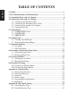
TABLE OF CONTENTS ENGLISH 1. Outline ..............................................................................................................1 2. Parts Identification and Nomenclature .........................................................2 3. Consumable Parts and AC Adapter ..............................................................4 4. Connecting Cables and AC Adapter ..............................................................5 4-1. Connecting the Interface Cable ...........................
Please access the following URL http://www.star-micronics.co.jp/service/frame_sp_spr_e.htm for the lastest revision of the manual. ENGLISH Appendix C: Interface .....................................................................................100 C-1. Serial Interface ...................................................................................100 C-2. Two-way parallel interface (IEEE1284) ............................................103 C-3. Peripheral Drive Connector ............................
This manual explains how to use the thermal printer TSP552II and provides points to note for safe use and prevention of problems and malfunctions. Before using the printer, please read this manual thoroughly to ensure its optimum use. The major features of the printer are as follows: 1. Prints at high speed (max. 130 mm/sec, 28 lines per second when the line feed is set to 3.75 mm) 2. Quality print (8 dots/mm) thanks to the high-density line thermal print head. 3. Low noise due to line thermal technology.
2. Parts Identification and Nomenclature ENGLISH Printer cover Control panel Open this cover to load or replace paper. Features LED indicators to indicate printer status and switches to operate the printer. Lever Pull down this lever to open the printer cover. Switch Used to turn on/off power to the printer. DIP switch Used to make various settings.
Before actually unpacking the printer, you should take a few minutes to think about where you plan to use it. Remember the following points when doing this. ✓ Choose a firm, level surface where the printer will not be exposed to vibration. ✓ The power outlet you plan to connect to for power should be nearby and unobstructed. ✓ Make sure that the printer is close enough to your host computer for you to connect the two. ✓ Make sure that the printer is not exposed to direct sunlight.
3. Consumable Parts and AC Adapter ENGLISH When consumable parts have run out, use those specified in the table below. Make sure that the AC adapter specified in the table is used. Use of consumable parts or AC adapter which are not specified in the table may result in damage to the printer, fire or electric shock. Parts Name Roll paper Specifications Thermal paper 0 Width: 80 - 1.0 mm Outer roll diameter: ø83 mm or less Core outer diameter: ø18 +0.5 0 mm Core inner diameter: ø12 ±0.
4-1. Connecting the Interface Cable Note: Before connecting/disconnecting the interface cable, make sure that power to the printer and all the devices connected to the printer is turned off. Also make sure the power cable plug is disconnected from the AC outlet. (1) Connect the interface cable to the connector on the rear panel of the printer. (2) In the case of a serial interface, tighten the connector screws. In the case of a parallel interface, fasten the connector clasps.
4-2. Connecting the Peripheral Drive Cable ENGLISH Note: Before connecting/disconnecting the peripheral drive cable, make sure that power to the printer and all the devices connected to the printer is turned off. Also make sure the power cable plug is disconnected from the AC outlet. (1) Connect the peripheral drive cable to the connector on the rear panel of the printer, and pass it through the cable hole provided at the bottom of the printer cover.
Note: Before connecting/disconnecting the AC adapter, make sure that power to the printer and all the devices connected to the printer is turned off. Also make sure the power cable plug is disconnected from the AC outlet. (1) Connect the AC adapter to the power cable. Note: Use only the standard AC adapter and power cable. (2) Cut off the blank cable hole on the printer cover using nippers. (3) Pass the AC adapter through the hole, and connect it to the connector on the printer.
4-4. Turning Power On Make sure that the AC adapter has been connected as described in 4-3. ENGLISH (1) Set the power switch located on the side of the printer to on. The POWER lamp on the control panel will light up. Power switch Important! We recommend that you unplug the printer from the power outlet whenever you do not plan to use it for long periods. Because of this, you should locate the printer so that the power outlet it is plugged into is nearby and easy to access.
5-1. PAPER FEED Switch Each time this switch is pressed, the paper feeds on line. When it is kept depressed, the paper feeds continuously. Note: This switch will be ineffective if no paper is loaded. 5-2. POWER LED This LED lights up when the power switch is set to on and power is supplied to the printer. 5-3. ERROR LED This LED lights up or blinks when any of the following errors occurs. Error LED No paper (paper end) is detected. Printer cover is open. Lights steadily.
6. Loading Paper ENGLISH 6-1. Loading New Roll Paper (1) Set the power switch to off to turn off power to the printer. (2) Pull the lever toward you to open the printer cover. Note: Make sure that the lever is pulled until it stops at the stopper. If the lever is not pulled up to the stopper, the printer cover may not open. (3) Peel the adhesive end off the paper. Note: Make sure that the entire adhesive area is removed, since no printing can be performed on that area.
Paper Note 2: Lock the printer cover by pressing on the center of the cover (indicated by an arrow in the figure below). If any part of the cover other than the center is pressed, the cover may not be locked properly. This may sometimes disables printing. – 11 – ENGLISH (5) Make sure that the paper is positioned straight, then close the printer cover gently. Note 1: Make sure that the paper is positioned straight.
ENGLISH (6) Set the power switch to on to turn on power to the printer. Make sure that the ERROR LED is not lit. Note: While the ERROR LED is lit, the printer will not accept any commands such as the print command, so make sure that the printer cover is locked properly. (7) Issue the cut command to cut off the end of the paper. 6-2. Removing Remaining Paper (1) Set the power switch to off to turn off power to the printer. (2) Pull the lever toward you to open the printer cover.
This printer supports two different command modes: the Star mode and the ESC/ POS mode. This chapter provides you with all of the commands supported by this printer. Important! Access the following URL for the latest version of this manual and for updates on supported commands: http://www.star-micronics.co.jp/ service/sp_sup_e.htm 7-1.
ENGLISH Control codes Hexadecimal codes Function “–” “0” “–” <0> 1B 2D 30 1B 2D 00 Cancel underlining “_” “1” “_” <1> 1B 5F 31 1B 5F 01 Select overlining “_” “0” “_” <0> 1B 5F 30 1B 5F 00 Cancel overlining “4” 1B 34 Select highlight printing “5” 1B 35 Cancel highlight printing 0F Inverted printing 12 Cancel inverted printing “E” 1B 45 Select emphasized printing “F” 1B 46 Cancel emphasized printing Commands t
Hexadecimal codes Function “J” n 1B 4A n One time n/4 mm feed “I” n 1B 49 n One time n/8 mm feed “B” n1 n2 ... <0> 1B 42 n1 n2 ... 00 Set vertical tab stops “D” n1 n2 ... <0> 1B 44 n1 n2 ... 00 Set horizontal tab stops “A” n1 n2 1B 1D 41 n1 n2 Absolute position setting “R” n1 n2 1B 1D 52 n1 n2 Relative position setting “a” n Alignment 1B 1D 61 n Commands to Print Dot Graphics Control codes Hexadecimal codes “K” n <0> m1 m2 .
Commands to Control Peripheral Devices Control codes ENGLISH Hexadecimal codes Function n1 n2 1B 07 n1 n2 Define drive pulse width for peripheral device #1 07 Control peripheral device #1 1C Control peripheral device #1 immediately 19 Control peripheral device #2 immediately 1A Control peripheral device #2 immediately Commands to Control Auto Cutter Control codes “d” n Hexadecimal codes 1B 64 n Function Partial-cut command to the auto cutter Othe
Control Code HT LF Hexadecimal Code 09 0A Function Horizontal tab Print line feed CR 0D Carriage return FF DLE EOT 0C 10 04 Page mode print and return Real time transmission of status DLE ENQ 10 05 Real time request to printer CAN ESC FF 18 1B FF Cancel print data in page mode Print page mode data ESC SP 1B 20 Set right space amount of character ESC ! ESC # 1B 1B 21 23 Universal print mode designation Set memory switch ESC $ nL nH 1B 24 ESC % ESC & 1B 1B 25 26 Designate/cance
Control Code Hexadecimal Code Function ENGLISH ESC { 1B 7B ESC ¥ nL nH FS p n m 1B 1C 9F 70 FS q n 1C 71 Define NV bit image GS ! GS $ 1D 1D 21 24 Designate character size Designate absolute position of vertical direction of characters in page mode 1D 2A Define download bit image 1D 1D 2F 3A Print download bit image Start/finish macro definition GS * GS / GS : Designate/cancel inverted printing nL n nH m Designate relative printing Print NV bit image GS B 1D 42 GS E n GS H
8-1. Preventing Paper Jams The paper should not be touched during ejection and before it is cut. Pressing or pulling the paper during ejection may cause a paper jam, paper cutting failure or line feed failure. 8-2. Removing Paper Jam If a paper jam occurs, clear it as described below. (1) Set the power switch to off to turn off power to the printer. (2) Pull the lever toward you to open the printer cover. Note: Make sure that the lever is pulled until it stops at the stopper.
ENGLISH (4) Position the roll paper straight and close the printer cover gently. Note 1: Make sure that the paper is positioned straight. If the printer cover is closed with the paper skewed, a paper jam may result. Note 2: Lock the printer cover by pressing on the center of the cover. If any part of the cover other than the center is pressed, the cover may not be locked properly. This may sometimes disable printing. (5) Set the power switch to on to turn on power to the printer.
9-1. Producing a Test Print To start test print, set the power switch to off, set the paper in place, then set the power switch to on while holding down the FEED switch. When a certain amount of printing is performed, the printer will cut the paper and stop automatically. An Example of Test Printout 9-2. Hexadecimal Dump Open the printer cover and set the power switch to on while holding down the FEED switch.After closing the printer cover, printer output will be in hexadecimal format.
10. Periodical Cleaning ENGLISH Printed characters may become partially unclear due to accumulated paper dust and dirt. To prevent such a problem, paper dust collected in the paper holder and paper transport section and on the surface of the thermal head must be removed periodically. Such cleaning is recommended to be carried out once a month. 10-1.Cleaning the Thermal Head To remove blackish dust collected on the surface of the thermal head, wipe it with alcohol (IPA).
1. Description de l’appareil ............................................................................... 25 2. Identification des pièces et nomenclature .................................................... 26 3. Consommables et adaptateur secteur .......................................................... 28 4. Câbles de connexion et adaptateur secteur .................................................29 4-1. Connexion du câble d’interface ...........................................................
FRANÇAIS – 24 –
Ce manuel fournit les explications nécessaires à l’utilisation optimale de l’imprimante thermique TSP552II et signale les points importants à respecter afin de garantir son utilisation en toute sécurité et de prévenir les problèmes et les pannes. Veuillez lire attentivement ce manuel dans son intégralité avant d’utiliser l’imprimante. Caractéristiques principales de l’imprimante : 1. Vitesse d’impression élevée (130 mm/sec, 28 lignes par sec, interligne réglé sur 3,75 mm) 2.
2. Identification des pièces et nomenclature Capot de l’imprimante Panneau des commandes FRANÇAIS Le panneau est équipé de commutateurs permettant la commande de l’imprimante et de DELs indiquant les statuts. Ouvrez ce capot pour charger ou remplacer le papier. Levier Tirez ce levier vers le bas pour ouvrir le capot de l’imprimante. Interrupteur Permet la mise sous et hors tension de l’appareil. Commutateurs DIP Ces commutateurs permettent d’effectuer divers réglages.
Emplacement de l’imprimante ✓ Choisissez une surface stable et de niveau sur laquelle l’imprimante ne sera exposée à aucune vibration. ✓ Assurez-vous que l’emplacement dispose d’une prise secteur proche et d’accès aisé. ✓ Assurez-vous que la distance entre l’imprimante et l’ordinateur-hôte vous permet de les raccorder aisément. ✓ Assurez-vous que l’imprimante n’est pas exposée directement aux rayons du soleil.
3. Consommables et adaptateur secteur FRANÇAIS Il convient d’utiliser exclusivement les types de papier figurant dans le tableau ci-dessous. Veillez également à utiliser l’adaptateur secteur qui figure dans le tableau. L’utilisation d’un type de papier et d’adaptateur ne figurant pas dans le tableau risque d’endommager l’imprimante, de causer un incendie ou une décharge électrique. Nom de pièce Rouleau de papier Caractéristiques Papier thermique Largeur: 80 - 01.
4. Câbles de connexion et adaptateur secteur Remarque:Avant de connecter ou déconnecter le câble d’interface, veillez à ce que l’imprimante et tous les appareils qui y sont connectés soient hors tension. Veillez également à débrancher le câble d’alimentation de la prise secteur. (1) Connectez le câble d’interface à la borne figurant sur le panneau arrière de l’imprimante. (2) Dans le cas d’une interface série, resserrez les vis du connecteur.
4-2. Connexion du câble de pilote de périphérique Remarque:Avant de connecter ou déconnecter le câble du pilote de périphérique, veillez à ce que l’imprimante et tous les appareils qui y sont connectés soient hors tension. Veillez également à débrancher le câble d’alimentation de la prise secteur. FRANÇAIS (1) Connectez le câble de pilote de périphérique à la borne figurant sur le panneau arrière de l’imprimante, puis faites le passer par l’orifice figurant au fond du capot de l’imprimante.
4-3. Connexion de l’adaptateur secteur optionnel (1) Connectez l’adaptateur secteur au câble d’alimentation. Remarque:Utilisez exclusivement l’adaptateur secteur et le câble d’alimentation destinés à l’imprimante. (2) Retirez le cache de l’orifice du câble à l’aide d’une pince. (3) Faites passer le câble de l’adaptateur par l’orifice et connectez-le à la borne de l’imprimante.
4-4. Mise sous tension de l’imprimante Assurez-vous d’avoir bien connecté l’adaptateur secteur comme décrit à la section 4-3. FRANÇAIS (1) Placez l’interrupteur d’alimentation, situé sur le côté de l’imprimante, sur la position sous tension. La DEL POWER s’allume au panneau des commandes. Interrupteur d’alimentation Attention! Nous vous recommandons de débrancher l’imprimate du secteur lorsque vous ne comptez pas l’utiliser pendant une période prolongée.
5. Panneau des commandes Le papier avance d’une ligne à chaque pression sur cette touche. Une pression continue sur la touche fera avancer le papier de façon continue. Remarque:Une pression sur cette touche n’a d’effet que si du papier est chargé dans l’imprimante. 5-2. DEL d’alimentation POWER Cette DEL s’allume lorsque l’interrupteur d’alimentation est placé sur hors tension et que l’appareil est alimenté par le secteur. 5-3.
6. Chargement du papier 6-1. Chargement d’un rouleau de papier neuf FRANÇAIS (1) Mettez l’imprimante hors tension. (2) Tirez le levier vers le bas afin d’ouvrir le capot de l’imprimante. Remarque:Veillez à tirer le levier tout à fait jusqu’à sa butée. Si le levier n’est pas tiré tout à fait, le capot pourrait ne pas s’ouvrir. (3) Retirez l’adhésif de l’extrémité du papier. Remarque:Veillez à bien retirer l’intégralité de l’adhésif. En effet, l’impression ne peut s’effectuer sur celui-ci.
FRANÇAIS (5) Veillez à ce que le papier soit placé bien droit, puis refermez doucement le capot de l’imprimante. Remarque 1: Le papier doit être placé bien droit. Si vous refermez le capot de l’imprimante alors que le papier est de travers (voir illustration), un bourrage peut se produire. Papier Remarque 2: Verrouillez le cache de l’imprimante en appuyant à l’endroit du capot repéré par la flèche dans l’illustration ci-dessous.
(6) Mettez l’imprimante sous tension. Assurez-vous que la DEL ERROR n’est pas allumée. Remarque:Tant que la DEL ERROR est allumée, l’imprimante n’accepte aucune commande. Il faut donc veiller à ce que le capot de l’imprimante soit verrouillé. FRANÇAIS (7) Lancez la commande de coupure de papier afin de couper l’extrémité du papier. 6-2. Retrait du papier (1) Mettez l’imprimante hors tension. (2) Tirez le levier vers le bas afin d’ouvrir le capot de l’imprimante.
7. Resume des commandes Attention! Pour obtenir la dernière version de ce manuel et pour les mises à jour des commandes supportées, consultez l’adresse URL suivante : http:// www.star-micronics.co.jp/service/sp_sup_e.htm. 7-1. Mode Star Commandes de sélection de caractères Code de contrôle Codes hexadécimaux Fonction “R” n 1B 52 n Sélection du jeu de caractères internationaux t n 1B 1D 74 n Sélectionne le tableau des caractères.
Code de contrôle Codes hexadécimaux 1B 2D 31 1B 2D 01 Fonction FRANÇAIS “–” “1” “–” <1> “–” “0” “–” <0> 1B 2D 30 1B 2D 00 Annulation de soulignement “_” “1” “_” <1> 1B 5F 31 1B 5F 01 Sélection de surlignement “_” “0” “_” <0> 1B 5F 30 1B 5F 00 Annulation de surlignement “4” 1B 34 Sélection d’impression surintensifiée Sélection de soulignement “5” 1B 35 Annulation d’impression surintensifiée 0F Impression inversée 12
Code de contrôle Codes hexadécimaux Fonction “z” “1” “z” <1> 1B 7A 31 1B 7A 01 Réglage d’espacement de ligne à 4 mm “0” 1B 30 Réglage d’espacement de ligne à 3 mm “J” n 1B 4A n Avance de n/4 mm à la fois “I” n 1B 49 n Réglage d’arrêts de tabulation verticale “D” n1 n2 ... <0> 1B 44 n1 n2 ...
Commandes de pilotage des périphériques FRANÇAIS Code de contrôle Codes hexadécimaux n1 n2 1B 07 n1 n2 Définition de la largeur d’impulsion d’entraînement du périphérique #1 07 Pilotage du périphérique #1 1C Pilotage immédiat du périphérique #1 19 Pilotage immédiat du périphérique #2 1A Pilotage immédiat du périphérique #2 Fonction Commandes de pilotage du mécanisme automatique de découpe Code de contrôle Codes hexadécimaux “d” n 1B 64 n Foncti
7-2.
Code de commande Code hexadécimal Fonction FRANÇAIS ESC t 1B 74 ESC { 1B 7B ESC ¥ nL nH FS p n m 1B 1C 9F 70 FS g n 1C 71 Définit l’image NV bit GS ! GS $ 1D 1D 21 24 Désignation de la taille de caractères Désignation de la position absolue de la direction verticale des caractères en mode de page GS GS / 1D 1D 2A 2F Définition de l’image bit téléchargée Impression de l’image bit téléchargée GS : 1D 3A Début/fin de la définition macro GS B GS E n 1D 1D 42 45 * Sélection du ta
8. Prévention et correction de bourrages de papier Il convient de ne jamais toucher le papier pendant son éjection et avant qu’il soit coupé. Appuyer ou tirer sur le papier pendant son éjection risque de provoquer un bourrage, des problèmes de coupure ou d’avance de ligne. 8-2. Correction de bourrages de papier En cas de bourrage de papier, procédez comme suit afin d’y remédier : (1) Mettez l’appareil hors tension. (2) Tirez le levier tout à fait vers le bas afin d’ouvrir le capot de l’imprimante.
(4) Veillez à insérer le rouleau de papier tout droit et refermez avec soin le capot de l’imprimante. Remarque 1: Le papier doit être placé bien droit. Si vous refermez le capot de l’imprimante alors que le papier est de travers (voir illustration), un bourrage peut se produire. Remarque 2: FRANÇAIS Verrouillez le cache de l’imprimante en appuyant à l’endroit du capot repéré par la flèche dans l’illustration ci-dessous.
9. Test d’impression Avant d’effectuer un test d’impression, commencez par mettre l’imprimante hors tension, insérez le papier, puis remettez l’imprimante sous tension tout en maintenant la touche d’avance FEED enfoncée. Après avoir imprimé pendant un certain temps, l’imprimante coupe le papier et s’arrête automatiquement. Exemple de test d’impression 9-2. Vidage hexadécimal Ouvrez le capot de l’imprimante et mettez l’imprimante sous tension tout en maintenant la touche d’avance FEED enfoncée.
10. Nettoyage FRANÇAIS Les caractères imprimés pourraient devenir partiellement illisibles en raison de l’accumulation de la poussière de papier et de crasse. Afin de prévenir ce genre de problème, il convient de nettoyer régulièrement la poussière qui s’accumule sur le support de papier, les passages du papier et la surface de la tête d’impression. Il est recommandé d’effectuer ce nettoyage une fois par mois. 10-1.
1. Kurzbeschreibung .........................................................................................49 2. Beschreibung und Bezeichnung der Geräteteile ......................................... 50 3. Verbrauchsteile und Netzteil ........................................................................ 52 4. Anschlußkabel und Netzteil ..........................................................................53 4-1. Anschließen des Schnittstellenkabels ..................................................
DEUTSCH – 48 –
1. Kurzbeschreibung Die wichtigsten Merkmale dieses Druckers sind wie folgt: 1. Druck mit hoher Geschwindigkeit (max. 130 mm/s 28 Zeilen/s bei Zeilenvorschub von 3,75 mm) 2. Hohe Druckqualität (8 Punkte/mm) dank hochdichter thermaler ZeilenDruckkopf. 3. Niedriges Betriebsgeräusch durch die Thermaldruckertechnik. 4. Drucken von Logos, Bons und Strichcodes ist möglich. 5. Die Druckstärke kann mit DIP-Schaltern eingestellt werden. 6. Ein automatisches Schneidwerk ist als Standardausstattung vorhanden. 7.
2. Beschreibung und Bezeichnung der Geräteteile DEUTSCH Abdeckung Bedienfeld Diese Abdeckung öffnen, um Papier einzusetzen oder zu entnehmen. Mit LED-Anzeigen zur Anzeige des Druckerstatus und Schalter zur Druckerbedienung. Hebel Diesen Hebel herunterziehen, um die Druckerabdeckung zu öffnen. Schalter Zum Ein- oder Ausschalten des Druckers. DIP-Schalter Für verschiedene Geräteeinstellungen.
Wahl eines Aufstellungsorts für den Drucker ✓ Den Drucker auf einem flachen, aber festen Untergrund aufstellen, wo keine Vibrationen vorhanden sind. ✓ Die verwendete Steckdose soll in der Nähe und frei zugänglich sein. ✓ Sicherstellen, daß der Drucker nahe genug am Computer ist, um die Geräte mit dem Druckerkabel verbinden zu können. ✓ Sicherstellen, daß der Drucker vor direktem Sonnenlicht geschützt ist. ✓ Sicherstellen, daß der Drucker ausreichend weit von Heizkörpern entfernt steht.
3. Verbrauchsteile und Netzteil Wenn die Verbrauchsteile verbraucht sind, besorgen Sie Ersatz entsprechend der unten gezeigten Tabelle. Verwendung von Verbrauchsteilen oder Netzteilen, die nicht den unten aufgeführten Beschreibungen entsprechend, kann zu Schäden am Drucker, Bränden oder elektrischen Schlägen führen. Bezeichnung Rollenpapier Beschreibung Thermopapier 0 Breite: 80 - 1.0 mm DEUTSCH Rollen-Außendurchmesser: ø83 mm oder weniger Kern-Außendurchmesser: ø18 +0.
4. Anschlußkabel und Netzteil 4-1. Anschließen des Schnittstellenkabels Hinweis:Vor dem Anschließen/Abtrennen des Schnittstellenkabels stellen Sie sicher, daß der Drucker und alle angeschlossenen Gerät ausgeschaltet sind. Außerdem sollte der Netzstecker abgezogen sein. (2) Bei einer seriellen Schnittstelle ziehen Sie die Steckerschrauben fest. Bei einer parallelen Schnittstelle befestigen Sie die Steckerklammern.
4-2. Anschließen des Peripheriegerätekabels Hinweis:Vor dem Anschließen/Abtrennen des Peripheriegerätekabels stellen Sie sicher, daß der Drucker und alle angeschlossenen Gerät ausgeschaltet sind. Außerdem sollte der Netzstecker abgezogen sein. DEUTSCH (1) Schließen Sie das Peripheriegerätekabel an die Buchse an der Rückseite des Druckers an, und führen Sie das Kabel durch das an der Unterseite der Druckerabdeckung vorhandene Loch.
4-3. Anschließen des optionalen Netzteils Hinweis:Vor dem Anschließen/Abtrennen des Netzteils stellen Sie sicher, daß der Drucker und alle angeschlossenen Gerät ausgeschaltet sind. Außerdem sollte der Netzstecker abgezogen sein. (1) Schließen Sie das Netzteil an das Netzkabel an. Hinweis:Verwenden Sie nur das vorgesehene Netzteil und Netzkabel. (3) Führen Sie das Kabel durch das Loch, und schließen Sie es an die Buchse am Drucker an.
4-4. Einschalten Stellen Sie sicher, daß das Netzteil angeschlossen ist, wie in 4-3 beschrieben. (1) Stellen Sie den Netzschalter an der Seite des Druckers in Ein-Stellung. Das POWER-Lämpchen am Bedienfeld leuchtet auf. DEUTSCH Netzschalter Wichtig! Wir empfehlen, den Netzstecker aus der Steckdose zu ziehen, wenn der Drucker längere Zeit lang nicht benutzt werden soll. Der Drucker sollte vorzugsweise an einem Platz aufgestellt werden, der leichten Zugang zur Netzsteckdose gewährt.
5. Bedienfeld 5-1. Papiereinzugknopf (PAPER FEED) Bei jedem Drücken dieses Knopfes wird das Papier um eine Zeile vorgeschoben. Wenn der Knopf gedrückt gehalten wird, wird das Papier kontinuierlich vorgeschoben. Hinweis:Dieser Knopf ist unwirksam, wenn kein Papier eingelegt ist. Diese LED leuchtet auf, wenn der Netzschalter in Ein-Stellung ist und Betriebsstrom am Drucker anliegt. 5-3. Fehler-LED (ERROR) Diese LED leuchtet oder blinkt, wenn einer der folgenden Fehler auftritt.
6. Einlegen von Papier 6-1. Einlegen einer neuen Papierrolle DEUTSCH (1) Stellen Sie den Netzschalter auf Aus-Stellung, um die Betriebsstromversorgung des Druckers abzuschalten. (2) Ziehen Sie den Hebel nach vorne, um die Druckerabdeckung zu öffnen. Hinweis:Stellen Sie sicher, daß der Hebel gezogen wird, bis er am Anschlag stoppt. Wenn der Hebel nicht bis zum Anschlag gezogen wird, kann es sein, daß sich die Druckerabdeckung nicht öffnen läßt. (3) Das Klebestück am Papierende abziehen.
DEUTSCH (5) Stellen Sie sicher, daß das Papier gerade ausgerichtet ist, und schließen Sie die Druckerabdeckung vorsichtig. Hinweis 1: Stellen Sie sicher, daß das Papier gerade ausgerichtet ist. Wenn die Druckerabdeckung bei schief liegendem Papier geschlossen wird, wie unten gezeigt, kann ein Papierstau auftreten. Papier Hinweis 2: Sperren Sie die Druckerabdeckung durch Drücken auf die Mitte der Abdeckung (in der Abbildung unten durch einen Pfeil gekennzeichnet).
(6) Stellen Sie den Netzschalter in Ein-Stellung, um den Drucker einzuschalten. Stellen Sie sicher, daß die ERROR-LED nicht leuchtet. Hinweis:Während die ERROR-LED leuchtet, akzeptiert der Drucker keine Befehle wie Druckbefehl; stellen Sie deshalb sicher, daß die Abdeckung richtig geschlossen ist. (7) Geben Sie den Befehl zum Abschneiden des Papierendes aus. 6-2. Entfernen des restlichen Papiers (1) Stellen Sie den Netzschalter auf Aus-Stellung, um den Drucker auszuschalten.
7. Zusammenfassung der Befehle Dieser Drucker unterstützt zwei verschiedene Befehlsmodi: den Star-Modus und den ESC/POS-Modus, In diesem Kapitel werden alle von diesem Drucker unterstützten Befehle aufgeführt. 7-1. Star-Betriebsart Befehle zum Ändern der Zeichendarstellung Steuerbefehle HexadezimalCodes Funktion “R” n 1B 52 n Internationalen Zeichensatz einstellen t n 1B 1D 74 n Zeichentabelle.
DEUTSCH Steuerbefehle HexadezimalCodes Funktion “_” “1” “_” <1> 1B 5F 31 1B 5F 01 Überstreichen aktivieren “_” “0” “_” <0> 1B 5F 30 1B 5F 00 Überstreichen deaktivieren “4” 1B 34 Hervorgehobenen Druck aktivieren “5” 1B 35 Hervorgehobenen Druck deaktivieren 0F Inversdruck aktivieren 12 Inversdruck deaktivieren “E” 1B 45 Fettdruck aktivieren “F” 1B 46 Fettdruck deaktivieren Befehle zum Festlegen der Seitengröße Steuerbefehle
Steuerbefehle HexadezimalCodes Funktion “J” n 1B 4A n Einmaliger Vorschub um n/4 mm “I” n 1B 49 n Einmaliger Vorschub um n/8 mm “B” n1 n2 ... <0> 1B 42 n1 n2 ... 00 Vertikale Tabulatoren definieren “D” n1 n2 ... <0> 1B 44 n1 n2 ...
Befehle zum Steuern von Peripheriegeräten Steuerbefehle HexadezimalCodes Funktion n1 n2 1B 07 n1 n2 Treiberimpuls für Peripheriegerät Nr. 1 definieren 07 Peripheriegerät Nr. 1 steuern 1C Peripheriegerät Nr. 1 ohne Verzögerung steuern 19 Peripheriegerät Nr. 2 ohne Verzögerung steuern 1A Peripheriegerät Nr.
7-2.
Steuerbefehle Hexadezimal-Codes Funktion ESC { 1B 7B ESC ¥ nL nH FS p n m 1B 1C 9F 70 FS g n 1C 71 Das NV-Bitbild definieren GS ! GS $ 1D 1D 21 24 Zeichengröße bestimmen Absolute Position der vertikalen Druckrichtung der Zeichen im Seiten-Modus bestimmen GS * Invertierter Druck EIN / AUS nL n nH m Relativen Druck bestimmen Das NV-Bitbild drucken DEUTSCH 1D 2A Download Bitmap-Grafik bestimmen GS / GS : 1D 1D 2F 3A Download Bitmap-Grafik drucken Makrodefinition starten / beenden
8. Verhindern und Beheben von Papierstau 8-1. Verhindern von Papierstau DEUTSCH Das Papier soll beim Ausgeben und vor dem Schneiden nicht berührt werden. Wenn das Papier beim Ausgeben gedrückt oder gezogen wird, kann ein Papierstau, ein Abschneidfehler oder ein Zeilenvorschubfehler verursacht werden. 8-2. Beheben von Papierstau Wenn ein Papierstau auftritt, beheben Sie ihn wie folgt. (1) Stellen Sie den Netzschalter auf Aus, um den Drucker auszuschalten.
(4) Stellen Sie sicher, daß das Papier gerade ausgerichtet ist, und schließen Sie die Druckerabdeckung vorsichtig. Hinweis 1: Stellen Sie sicher, daß das Papier gerade ausgerichtet ist. Wenn die Druckerabdeckung bei schief liegendem Papier geschlossen wird, kann ein Papierstau auftreten. Hinweis 2: Sperren Sie die Druckerabdeckung durch Drücken auf die Mitte der Abdeckung. Wenn ein anderer Teil der Abdeckung als die Mitte gedrückt wird, kann die Abdeckung nicht richtig geschlossen werden. Dadurch kann u.U.
9. Testdruck-Verfahren 9-1. Erstellen eines Testdrucks Zum Starten des Testdrucks schalten Sie den Drucker mit dem Netzschalter aus, setzen das Papier richtig ein, und schalten dann den Drucker bei gedrückt gehaltener FEED-Knopf ein. Der Testdruck stoppt automatisch nach dem Ausdruck der vorgegebenen Druckmenge, und der Drucker schneidet das Papier ab. DEUTSCH Beispiel eines Testdrucks 9-2.
10. Regelmäßige Reinigung Die Druckzeichen können durch Ansammlung von Papierstaub und anderem Schmutz unscharf werden. Um das zu verhindern, muß im Papierhalter und in der Papiertransportstufe angesammelter Staub von Zeit zu Zeit entfernt werden. Eine derartige Reinigung sollte etwa einmal im Monat ausgeführt werden. 10-1.Reinigen des Thermalkopfes DEUTSCH Zum Entfernen von schwärzlichem Staub auf der Oberfläche des Thermalkopfes diesen mit Isopropylalkohol (IPA) abwischen.
1. Descrizione ..................................................................................................... 73 2. Identificazione delle parti e nomenclatura .................................................. 74 3. Parti soggette a consumo e trasformatore CA ............................................ 76 4. Cavi di collegamento e trasformatore CA ................................................... 77 4-1. Collegamento del cavo interfaccia .......................................................
ITALIANO – 72 –
1. Descrizione Le caratteristiche principali della stampante sono come segue: 1. Stampa ad alta velocità (mass. 130 mm/sec, 28 righe al secondo quando l’avanzamento di riga standard è impostato su 3,75 mm) 2. Stampa di qualità (8 punti/mm) grazie alla testina di stampa termica a linea di alta densità. 3. Rumore ridotto grazie alla Tecnologia in linee termica. 4. Possibilità di stampare marchi, coupon e codici a barre. 5. Densità di stampa selezionabile tramite interruttori DIP. 6.
2. Identificazione delle parti e nomenclatura Coperchio stampante Pannello di controllo Aprire questo coperchio per inserire o sostituire la carta. Dispone di indicatori LED che indicano lo stato della stampante e di interruttori per controllare la stampante. Leva Abbassare questa leva per aprire il coperchio della stampante. Interruttore Usarlo per accendere/ spegnere la stampante. Interruttori DIP Usarli per eseguire varie impostazioni.
Scelta di un luogo per la stampante ✓ Scegliere una superficie stabile e in piano, dove la stampante non sia esposta a vibrazioni. ✓ La presa di corrente che si intende usare per la stampante deve essere vicina e libera da ostacoli. ✓ La stampante deve essere abbastanza vicina al computer da permettere il collegamento tra i due. ✓ Assicurarsi che la stampante non sia esposta alla luce solare diretta. ✓ Assicurarsi che la stampante sia lontana da caloriferi e altre fonti di calore elevato.
3. Parti soggette a consumo e trasformatore CA Quando le parti soggette a consumo si sono esaurite, usare quelle specificate nella seguente tabella. Assicurarsi di usare il trasformatore CA specificato nella tabella. L’uso di parti soggette a consumo o di un trasformatore CA diversi da quanto specificato nella tabella può causare danni alla stampante, incendi o scosse elettriche. Nome della parte Carta in rotolo Specifiche Carta termica Larghezza: 80 - 01.
4. Cavi di collegamento e trasformatore CA 4-1. Collegamento del cavo interfaccia Nota: Prima di collegare/scollegare il cavo interfaccia, assicurarsi che la stampante e tutti i dispositivi collegati alla stampante siano spenti. Inoltre assicurarsi che la spina del cavo di alimentazione sia scollegata dalla presa di corrente. (1) Collegare il cavo interfaccia al connettore sul pannello posteriore della stampante.
4-2. Collegamento del cavo di controllo periferiche Nota: Prima di collegare/scollegare il cavo di controllo periferiche, assicurarsi che la stampante e tutti i dispositivi collegati alla stampante siano spenti. Inoltre assicurarsi che la spina del cavo di alimentazione sia scollegata dalla presa di corrente. (1) Collegare il cavo di controllo periferiche al connettore sul pannello posteriore della stampante e farlo passare attraverso il foro sul fondo del coperchio stampante.
4-3. Collegamento del trasformatore CA opzionale Nota: Prima di collegare/scollegare il trasformatore CA, assicurarsi che la stampante e tutti i dispositivi collegati alla stampante siano spenti. Inoltre assicurarsi che la spina del cavo di alimentazione sia scollegata dalla presa di corrente. (1) Collegare il trasformatore CA al cavo di alimentazione. Nota: Usare solo il trasformatore CA e cavo di alimentazione standard.
4-4. Accensione Assicurarsi che il trasformatore CA sia stato collegato come indicato nella sezione 4-3. (1) Regolare su ON l’interruttore di alimentazione situato sul lato della stampante. La spia POWER sul pannello di controllo si illumina. ITALIANO Interruttore di alimentazione Importante! Consigliamo di scollegare la stampante dalla presa di corrente quando si prevede di non usarla per un lungo periodo.
5. Pannello di controllo 5-1. Interruttore PAPER FEED A ciascuna pressione di questo interruttore la carta avanza di una riga. Se si tiene premuto l’interruttore, la carta avanza continuamente. Nota: Questo interruttore non funziona se non è inserita carta. 5-2. Spia POWER Questa spia a LED si illumina quando l’interruttore di alimentazione è attivato e la stampante riceve alimentazione. 5-3.
6. Caricamento della carta 6-1. Caricamento di un nuovo rotolo di carta (1) Regolare l’interruttore di alimentazione su OFF per spegnere la stampante. (2) Tirare la leva verso di sè per aprire il coperchio stampante. Nota: Assicurarsi di tirare la leva fino a che si arresta al fermo. Se la leva non viene tirata fino al fermo, il coperchio stampante può non aprirsi. (3) Togliere l’adesivo dall’estremità della carta.
ITALIANO (5) Assicurarsi che la carta sia collocata ben diritta e quindi chiudere delicatamente il coperchio stampante. Nota 1: Assicurarsi che la carta sia ben diritta. Se si chiude il coperchio stampante con la carta storta come mostrato sotto, si può verificare un inceppamento della carta. Carta Nota 2: Bloccare il coperchio della stampante premendo sul centro del coperchio (indicato dalla freccia nella figura sotto).
(6) Regolare su ON l’interruttore di alimentazione per accendere la stampante. Assicurarsi che la spia ERROR non sia illuminata. Nota: Mentre la spia ERROR è illuminata, la stampante non accetta alcun comando come il comando di stampa, per cui assicurarsi che il coperchio della stampante sia bloccato correttamente. (7) Dare il comando di taglio per tagliare l’estremità della carta. 6-2. Rimozione della carta rimanente (1) Regolare l’interruttore di alimentazione su OFF per spegnere la stampante.
7. Elenco del comandi Questa stampante supporta due diversi modi di comando: il modo Star e il modo ESC/POS. Questo capitolo fornisce tutti i comandi supportati dalla stampante. Importante! Accedere alla seguente URL per la versione più recente di questo manuale e per aggiornamenti sui comandi supportati: http://www.starmicronics.co.jp/service/sp_sup_e.htm 7-1.
Codici di controllo Codici esadecimali Funzione “–” “0” “–” <0> 1B 2D 30 1B 2D 00 Annulla lo stile sottolineato “_” “1” “_” <1> 1B 5F 31 1B 5F 01 Seleziona lo stile barrato “_” “0” “_” <0> 1B 5F 30 1B 5F 00 Annulla lo stile barrato “4” 1B 34 Seleziona la stampa evidenziata “5” 1B 35 Annulla la stampa evidenziata 0F Seleziona la stampa rovesciata 12 Annulla la stampa rovesciata “E” 1B 45 Seleziona la stampa enfatizzata
Codici di controllo Codici esadecimali Funzione “J” n 1B 4A n Singolo spostamento in avanti di n/4 mm “I” n 1B 49 n Singolo spostamento in avanti di n/8 mm “B” n1 n2 ... <0> 1B 42 n1 n2 ... 00 Imposta tabulazioni verticali “D” n1 n2 ... <0> 1B 44 n1 n2 ...
Comandi di controllo di unità periferiche Codici di controllo Codici esadecimali Funzione n1 n2 1B 07 n1 n2 Definisce l’ampiezza del segnale di attivazione dell’unità periferica #1 07 Invia un segnale all’unità periferica #1 1C Invia subito un segnale all’unità periferica #1 19 Invia subito un segnale all’unità periferica #2 1A Invia subito un segnale all’unità periferica #2 Comandi di controllo della taglierina automatica ITALIANO Codici di controllo C
7-2.
Codice di controllo Codice esadecimale ESC t 1B 74 ESC { ESC ¥ nL nH 1B 18 7B 9F nL nH FS p n m 1C 70 n m FS g n GS ! 1C 1D 71 21 Definisce immagine di bit NV Imposta la dimensione del carattere GS $ 1D 24 Imposta la posizione di stampa assoluta dei caratteri in direzione verticale in modo pagina GS GS / 1D 1D 2A 2F Definisce la grafica bitmap trasferibile Stampa la grafica bitmap trasferibile GS : 1D 3A Inizia/termina la definizione della macro GS B GS E n 1D 1D 42 45 * F
8. Prevenzione e soluzione degli inceppamenti della carta 8-1. Prevenzione degli inceppamenti della carta ITALIANO La carta non deve essere toccata durante l’espulsione e prima che sia tagliata. Se si preme o si tira la carta durante l’espulsione si può verificare un inceppamento della carta, un mancato taglio della carta o un avanzamento di riga mancato. 8-2. Eliminazione degli inceppamenti della carta Se si verifica un inceppamento della carta, eliminarlo come descritto di seguito.
(4) Collocare diritto il rotolo di carta e chiudere delicatamente il coperchio stampante. Nota 1: Assicurarsi che la carta sia ben diritta. Se si chiude il coperchio stampante con la carta storta, si può verificare un inceppamento della carta. Nota 2: Bloccare il coperchio della stampante premendo sul centro del coperchio. Se si preme una parte del coperchio diversa dal centro, il coperchio può non bloccarsi correttamente. Questo a volte rende impossibile la stampa.
9. Metodo per la stampa di prova 9-1. Produzione di uno stampato di prova Per avviare la stampa di prova, regolare su OFF l’interruttore di alimentazione, inserire la carta e quindi regolare l’interruttore di alimentazione su ON tenendo premuto il interruttore FEED. Quando è stato eseguita una certa quantità di stampa, la stampante taglia la carta e si ferma automaticamente. ITALIANO Esempio di stampato di prova 9-2.
10. Pulizia periodica I caratteri stampati possono diventare parzialmente poco chiari a causa dell’accumulo di polvere di carta e sporcizia. Per evitare tale problema, è necessario rimuovere periodicamente la polvere di carta accumulata nel comparto carta, nella sezione di trasporto carta e sulla superficie della testina termica. Si consiglia di eseguire questa pulizia una volta al mese. 10-1.
Appendix A: Specifications A-1. General Specifications Direct line thermal printing 130 mm/s Note: Print duty is 16.5% or less. (3) Dot density 8 dots/mm (0.125 mm/dot) (4) Number of print columns 48 (5) Roll paper Refer to chapter 3 for details on the recommended paper. Paper width: 80- 01.0 mm Roll diameter: ø83 mm or less External diameter of core: ø18 +0.5 0 mm Internal diameter of core: ø12 ± 0.
A-4. Power Supply (1) AC Adaptor (2) Input (3) Output (4) Plug PS48-24A, switching type 90 to 264V AC, 50/60Hz 24V DC ±5%, 2.0A 3-pin POWER JACK TCP 8927 (Hoshiden brand or equivalent.) Important! • When using a printer power supply other than the optional AC adaptor (PS48-24A), be sure that the following cautions are observed. • Use a power supply of DC 24 V ± 5% and more than 2.0 A. • Be careful about installing the printer in an area where there is noise.
Appendix B: Dip Switch Setting Two DIP switches are provided at the bottom of the printer, and can be set as given in the table below. Be sure to set the power switch to off before changing the settings. It is recommended to use a pointed item like a pen or flat-blade driver screw to change the settings. The settings will become effective when the power switch is set to on again. B-1. Serial Interface Type ON ON OFF No. 1 2 3 4 5 6 7 8 OFF No.
Table 1 Baud Rate Data rate (bps) SW1-7 SW1-8 2400 ON ON 4800 OFF ON 9600 ON OFF 19200 OFF OFF Table 2 Print Density Print Density SW2-3 SW2-4 Contents of Test Print Page Light ON ON ▼ OFF ON Level 2 ON OFF Level 3 OFF OFF Level 4 (Standard) ▼ Dark Level 1 B-2. Parallel Interface Type ON ON OFF No. 1 2 3 4 5 6 7 8 OFF No.
DIP-SW 2 Switch 1 2 Function ON Handshaking conditions (conditions for BUSY) OFF Receive buffer full Offline or receive buffer full Code (Star mode) Form Feed Cut Command Graphic Adjustment (ESC/POS mode) 203 DPI Adjust for 180 DPI Print density See Table 3. 5 Command STAR ESC/POS 6 Should not be changed (should be set to on).
Appendix C: Interface C-1. Serial Interface C-1-1.
C-1-2. RS-232C Connector 1 Signal name FG Frame ground 2 TXD Send data 3 RXD 4 RTS 5 CTS Clear to send IN 6 DSR Data set ready IN 7 SG 8 – Pin No. I/O direction *14 Signal name SG2 OUT 15 – Receive data IN 16 – Request to send OUT 17 – *18 +24V Function Pin No.
C-1-3. Cable Connections (1) The followings are a recommended interface cable connections.
C-2. Two-way parallel interface (IEEE1284) C-2-1. Interface specifications APPENDIX (a) Forward channel The forward channel mode is the mode in which the widely used Centronics interface is regulated. • Data transfer method: 8 bit parallel • Synchronizing system: Externally supplied nStrobe signal • Handshake: nAck signal and Busy signal • Signal level: All signals are TTL compatible. (b) Reverse channel The transfer of status data from the printer to the host is only carried in the nibble mode.
C-2-2. Names of connectors and signals (18) (1) Amphenol Conforms with connector 57-30360 (36) (19) (1) Forward channel No. APPENDIX Input/output No.
(2) Reverse channel Input/output No. Signal name 1 HostClk Signal name IN 19 HostClk-RET 2 DATA1 IN 20 DATA1-RET 3 DATA2 IN 21 DATA2-RET 4 DATA3 IN 22 DATA3-RET 5 DATA4 IN 23 DATA4-RET 6 DATA5 IN 24 DATA5-RET 7 DATA6 IN 25 DATA6-RET 8 DATA7 IN 26 DATA7-RET 9 DATA8 IN 27 DATA8-RET 10 PtrClk OUT 28 PtrClk-RET 11 PtrBusy OUT 29 PtrBusy-RET 12 AckDataReq OUT 30 INIT-RET 13 Xflag OUT 31 INIT 14 HostBusy IN 32 DataAvail 15 N.C.
C-3. Peripheral Drive Connector 1 Signal name FG Frame ground I/O direction — 2 DRD1 Drive signal 1 OUT 3 +24V Drive power OUT 4 +24V Drive power OUT 5 DRD2 Drive signal 2 OUT 6 DRSNS Sense signal IN Pin No. Function 6 1 APPENDIX Printer side User side 1 with shield 2 Peripheral drive solenoid 1 (24 Ω or high) 3 0 ~ 4.
APPENDIX Notes 1. A shield cable must be used. 2. It is not possible to drive two drives simultaneously. 3. The peripheral drive duty must satisfy the following. ON time / (ON time + OFF time) ≤ 0.2 4. Power to the peripheral drive must be supplied from the printer (connector pin 4). 5. The resistance of the peripheral drive solenoid must be 24 Ω or higher. If it is lower than 24 Ω, over-current may flow into the solenoid, causing the solenoid to burn.
C-4. Power Connector 1 Signal name +24V 2 SG 3 N.C. Pin No. Function Drive power I/O direction IN 1 3 2 Note 1: This power connector is used to supply the control and mechanical sections of the printer. Note 2: This power connector must not be used to supply power if power is supplied from the interface connector. Doing so may result in malfunction, fire or electric shock.
ELECTRONIC PRODUCTS DIVISION STAR MICRONICS CO., LTD. OVERSEAS SUBSIDIARY COMPANIES STAR MICRONICS AMERICA, INC. 536 Nanatsushinnya, Shimizu, Shizuoka, 424-0066 Japan Tel: 0543-47-0112, Fax: 0543-48-5013 1150 King Georges Post Road, Edison, NJ 08837-3729 U.S.A. Tel: 732-623-5555, Fax: 732-623-5590 Please access the following URL http://www.star-micronics.co.jp/service/frame_sp_spr_e.htm for the lastest revision of the manual. STAR MICRONICS U.K. LTD.