THERMAL PRINTER TSP800 SERIES USER’S MANUAL MODE D’EMPLOI BEDIENUNGSANLEITUNG MANUALE DI ISTRUZIONI
Federal Communications Commission Radio Frequency Interference Statement This equipment has been tested and found to comply with the limits for a Class A digital device, pursuant to Part 15 of the FCC Rules. These limits are designed to provide reasonable protection against harmful interference when the equipment is operated in a commercial environment.
1. Parts Identification and Nomenclature ......................................................... 1 1-1. Choosing a place for the printer ............................................................. 3 1-2. Mounting hardware for wall mount model ............................................ 3 2. Consumable Parts and AC Adapter .............................................................. 6 3. Connecting Cables and AC Adapter .............................................................. 8 3-1.
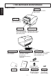
1. Parts Identification and Nomenclature ENGLISH Standard Model Printer cover Open this cover to load or replace paper. Power switch Used to turn on/off power to the printer. Control panel Cover open lever Features LED indica- Pull this lever in the tors to indicate printer direction of the arrow to status and switches to open the printer cover. operate the printer. Interface connector For connection to a host computer.
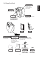
Wall Mount/Stand Model Power switch Used to turn on/off power to the printer. Printer cover Control panel Open this cover to load or replace paper. Features LED indicators to indicate printer status and switches to operate the printer. Interface connector For connection to a host computer. Peripheral drive connector Connects to peripheral units such as cash drawers, etc. Do not connect this to a telephone. Bracket Stand (Option) (Option) Power connector For connection of the AC adapter.
1-1. Choosing a place for the printer ENGLISH Before actually unpacking the printer, you should take a few minutes to think about where you plan to use it. Remember the following points when doing this. ✓ Choose a firm, level surface where the printer will not be exposed to vibration. ✓ The power outlet you plan to connect to for power should be nearby and unobstructed. ✓ Make sure that the printer is close enough to your host computer for you to connect the two.
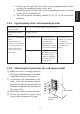
1-2-1. Specifications of the wall mounting bracket Wall mounting bracket outer dimensions 121 × 168 × 14.5 mm (Width × Height × Depth) Wall mounting bracket weight Approx. 0.27 kg.
Wood structure wall Concrete structure wall ENGLISH • Locate the beams in the wall and mount using them. • Do not tighten the screws or anchors to locations with one wall sheet. Always make sure that the screws penetrate the beams. (This is so the weight of the printer can be supported.) • Drive the anchor nuts into the wall and tighten the screws. Anchor nuts Screw Beam Concrete wall Wall Position the printer over the wall bracket and then slide it downwards to set it in place.
When consumable parts have run out, use those specified in the table below. Make sure that the AC adapter specified in the table is used. Use of consumable parts or AC adapter which are not specified in the table may result in damage to the printer, fire or electric shock. (1) Roll paper specification Thermal paper Thickness: 65~150 µm Width: 111.5±0.5 mm Outer roll diameter: ø100 mm or less Take up paper roll width: 112 +0.
Kanzaki Specialty Papers Inc. (KSP) ENGLISH P320RB (2 color paper: Red & Black), 65 µm (thickness) P320BB (2 color paper: Blue & Black), 65 µm (thickness) Depending on the type and thickness of the paper, it may be necessary to change the settings for printing darkness. To change the darkness settings, use the printing darkness settings command ‘d’ n. Refer to the separate programmer’s manual for details.
3-1. Interface Cable Note that the interface cable is not provided. Please use a cable that meets specifications. CAUTION Before connecting/disconnecting the interface cable, make sure that power to the printer and all the devices connected to the printer is turned off. Also make sure the power cable plug is disconnected from the AC outlet. 3-1-1. Serial Interface (RS-232C) Cable (1) Make sure the printer is turn off. (2) Connect the interface cable to the connector on the rear panel of the printer.
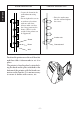
3-1-2. Parallel Interface Cable (1) Make sure the printer is turn off. ENGLISH (2) Affix the ferrite core onto the cable as shown in the illustration. Ferrite core Interface cable 5 cm (maximum) (3) Pass the fastener through the ferrite core. Fastener Pull and cut (4) Loop the fastener around the cable and lock it. Use scissors to cut off any excess.
(5) Connect the interface cable to the connector on the rear panel of the printer. ENGLISH (6) Fasten the connector clasps. Parallel interface cable 3-1-3. Connecting USB Cable Affix the ferrite core onto the USB cable as shown in the illustration below and make sure to pass the cable through the cable support as shown in the illustration.
3-1-4. Connecting Ethernet Cable (1) Make sure the printer is turned off. ENGLISH (2) Affix the ferrite core onto the ethernet cable as shown in the illustration below. Ethernet cable Ferrite core (3) Pass the fastener through the ferrite core. 10cm (maximum) Fastener (4) Loop the fastener around the cable and lock it. Use scissors to cut off any excess. (5) Connect the ethernet cable to the connector on the interface board. Then, connect the other end of the cable to your computer.
You can connect a peripheral unit to the printer using a modular plug. The following describes how to make the actual connection. See “Modular plug” on page 126 for details about the type of modular plug that is required. Note that this printer does not come with a modular plug or wire, so it is up to you to obtain one that suits your needs. Important! Make sure that the printer is turned off and unplugged from the AC outlet and that the computer is turned off before making connections.
3-3. Connecting the Optional AC Adapter ENGLISH Note: Before connecting/disconnecting the AC adapter, make sure that power to the printer and all the devices connected to the printer is turned off. Also make sure the power cable plug is disconnected from the AC outlet. (1) Connect the AC adapter to the power cable. Note: Use only the standard AC adapter and power cable. (2) Connect AC adapter to the connector on the printer. (3) Insert the power cable plug into an AC outlet.
3-4. Turning Power On (1) Set the power switch located on the front of the printer to on. The POWER lamp on the control panel will light up. Power switch Important! We recommend that you unplug the printer from the power outlet whenever you do not plan to use it for long periods. Because of this, you should locate the printer so that the power outlet it is plugged into is nearby and easy to access. – 14 – ENGLISH Make sure that the AC adapter has been connected as described in 3-3.
4. Control Panel and Other Functions ENGLISH 4-1. Control Panel 1 POWER lamp (Green LED) Lights when the power is ON POWER ERROR 2 ERROR lamp (Red LED) Indicates various errors in combination with POWER lamp FEED 3 FEED button 2 ERROR lamp (Red LED) 1 POWER lamp (Green LED) 3 FEED button Press the FEED button to feed roll paper. 4-2. Errors 1) Automatically recoverable error POWER lamp ERROR lamp Recovery Conditions Head high temperature detection Flashes at 0.
Error Description POWER lamp ERROR lamp Recovery Conditions RAM error Off On This is not a recoverable error. Consult dealer for repairs. EPROM error Flashes at 0.25 second intervals Flashes at 0.25 second intervals This is not a recoverable error. Consult dealer for repairs. Thermistor error Flashes at 0.5 second intervals Flashes at 0.5 second intervals Power supply error Flashes at 1 second intervals Flashes at 1 second intervals This is not a recoverable error.
4-3. Self Printing ENGLISH (1) Test Printing Turn the power on while holding the FEED button depressed. Test printing will be performed according to the Ver. No., DIP switch settings and character order. When the FEED button is depressed at the time of the end of test printing, only the characters will be printed out repeatedly.
– 18 – ENGLISH (2) Hexadecimal Dump Mode Open the printer cover, then turn the power on while holding the FEED button. When the cover is closed, “*** HEX DUMP PRINTING ***” is printed, and the printer enters the Hexadecimal Dump Mode. Each of the signals sent from the computer to the printer will be printed out in hexadecimal code. This function allows you to check if a control code sent to the printer by the program being used is correct or not.
5. Loading the Roll Paper ENGLISH Be sure to use roll paper that matches the printer’s specification. Push the Cover open lever, and open the printer cover. Cover open lever Roll paper Tension bar (Standard Model) Tension bar Roll paper While observing the direction of the roll, set the paper roll into the hollow, and pull on the leading edge of the paper toward you.
Note: Make sure that the printer cover is securely closed. Important! 1. Do not touch the cutter blade. · There is a cutter inside the paper outlet slot. Not only should you not put your hand in the paper outlet slot while printing is in progress, never put your hand into the outlet even when printing is not in progress. · The printer cover can be opened when replacing the paper.
6. Adjusting the Near-end Sensor ENGLISH Use the following procedure to adjust the near-end sensor so it is compatible with the size of roll paper you are using. 1 Open the printer cover. 2 Determine the diameter of the roll paper you are using and find the required setting in the table below. 3 Insert the tip of a ballpoint pen or similar pointer object into the hole of the adjuster. While pressing the adjuster, slide it up or down to the setting that matches the roll paper you are using.
Paper thickness (µm) 65 When using the paper roll with a core whose inside diameter (A):ø12, outside diameter (B):ø18 Detected diameter (C) Remained paper length (Approx. mm) (Approx. m) Level 1 Level 2 Level 3 Level 1 Level 2 ø23 ø27 ø31 2.5 4.9 7.7 2.1 4.2 6.7 75 Paper thickness (µm) Level 3 When using the paper roll with a core whose inside diameter (A): ø25.4, outside diameter (B):ø32 Detected diameter (C) Remained paper length (Approx. mm) (Approx.
7. Preventing and Clearing Paper Jams ENGLISH 7-1. Preventing Paper Jams The paper should not be touched during ejection and before it is cut. Pressing or pulling the paper during ejection may cause a paper jam, paper cutting failure or line feed failure. 7-2. Removing Paper Jam If a paper jam occurs, clear it as described below. (1) Set the power switch to off to turn off power to the printer. (2) Pull the lever toward you to open the printer cover. (3) Remove the jammed paper.
Printed characters may become partially unclear due to accumulated paper dust and dirt. To prevent such a problem, paper dust collected in the paper holder and paper transport section and on the surface of the thermal head must be removed periodically. Such cleaning is recommended to be carried out once six month or one million lines. 8-1. Cleaning the Thermal Head To remove blackish dust collected on the surface of the thermal head, wipe it with alcohol (IPA).
1. Identification des pièces et nomenclature ....................................................27 1-1. Emplacement de l’imprimante .............................................................29 1-2. Montage du modèle mural ...................................................................29 2. Consommables et adaptateur secteur ..........................................................32 3. Câbles de connexion et adaptateur secteur .................................................34 3-1.
1. Identification des pièces et nomenclature Modèle standard Capot de l’imprimante Ouvrez ce capot pour charger ou remplacer le papier. FRANÇAIS Interrupteur d’alimentation Permet la mise sous et hors tension de l’appareil. Panneau des commandes Le panneau est équipé de commutateurs permettant la commande de l’imprimante et de DELs indiquant les statuts. Connecteur d’interface Ce connecteur vous permet de connecter l’imprimante à l’ordinateur-hôte.
Modèle mural/avec socle Levier d’ouverture du capot Tirez ce levier dans le sens de la flèche pour ouvrir le capot de l’imprimante. Capot de l’imprimante Panneau des commandes Ouvrez ce capot pour charger ou remplacer le papier. Le panneau est équipé de commutateurs permettant la commande de l’imprimante et de DELs indiquant les statuts. Connecteur d’interface Connecteur d’appareil périphérique Ce connecteur vous permet de connecter l’imprimante à l’ordinateur-hôte.
1-1. Emplacement de l’imprimante Avant de déballer l’imprimante, déterminez l’emplacement où vous souhaitez l’installer. Veuillez observer les points ci-dessous lors de votre choix. FRANÇAIS ✓ Choisissez une surface stable et de niveau sur laquelle l’imprimante ne sera exposée à aucune vibration. ✓ Assurez-vous que l’emplacement dispose d’une prise secteur proche et d’accès aisé. ✓ Assurez-vous que la distance entre l’imprimante et l’ordinateur-hôte vous permet de les raccorder aisément.
FRANÇAIS ✓ Le diamètre de vis recommandé est de 4 mm. ✓ Veillez toujours à utiliser les huit (8) orifices de vis du support de montage. ✓ Montez le support au mur en veillant à ce sa position ne diffère que de ±2° maximum de la verticale. ✓ Le mur destiné à recevoir l’appareil doit être à un angle de 90°±2° par rapport à l’horizontale. 1-2-1.
Mur en bois Mur en béton • Montez les vis dans la charpente d’un mur. FRANÇAIS • Ne pas serrer les vis ou les ancrages dans la cloison seule. Veillez bien à les monter dans un poteau de la charpente, ceci afin d’assurer que les vis puissent supporter le poids de l’imprimante. • Monter les écrous d’ancrage dans le mur et serrer les vis. Écrous d’ancrage Vis Poteau Mur en béton Cloison Disposer l’imprimante légèrement audessus du support et la faire glisser vers le bas.
2.
Kanzaki Specialty Papers Inc. (KSP) P320RB (papier 2 couleurs : rouge et noir), 65 µm (épaisseur) P320BB (papier 2 couleurs : bleu et noir), 65 µm (épaisseur) Suivant le type et l’épaisseur du papier, il peut être nécessaire de changer le réglage de clarté d’impression. Pour changer le réglage de la clarté d’impression, utilisez la commande de réglage de clarté d’impression ‘d’n. Reportez-vous au manuel de programmation séparé pour les détails.
3. Câbles de connexion et adaptateur secteur 3-1. Câble d’interface ATTENTION Avant de connecter ou déconnecter le câble d’interface, veillez à ce que l’imprimante et tous les appareils qui y sont connectés soient hors tension. Veillez également à débrancher le câble d’alimentation de la prise secteur. 3-1-1. Câble d’interface série (RS-232C) (1) Assurez-vous que l’imprimante est hors tension. (2) Connectez le câble d’interface à la borne figurant sur le panneau arrière de l’imprimante.
3-1-2. Interface parallèle (1) Assurez-vous que l’imprimante est hors tension. (2) Fixez la grande gaine en ferrite sur le câble comme illustré. FRANÇAIS Tore de ferrite Interface câble 5 cm (maximum) (3) Passez l’attache dans le tore de ferrite. Attache Tirez et coupez (4) Passez l’attache autour du tore de ferrite et serrez-la. Coupez l’extrémité de l’attache à l’aide de ciseaux.
(5) Connectez le câble d’interface à la borne figurant sur le panneau arrière de l’imprimante. Câble d’interface parallèle 3-1-3. Branchement d’un câble USB Attachez le tore de ferrite au câble USB conformément à l’illustration ci-dessous, et veiller à passer le câble par le support de câble illustré. 4 cm (maximum) Tore de ferrite – 36 – FRANÇAIS (6) Attachez les fermoirs du connecteur.
3-1-4. Branchement d’un câble ethernet (1) Assurez-vous que l’imprimante est hors tension. FRANÇAIS (2) Attachez le tore de ferrite au câble ethernet conformément à l’illustration. Câble ethernet Tore de ferrite 10 cm (maximum) (3) Passez le collier de serrage par le tore de ferrite. Collier de serrage (4) Passez le collier de serrage autour du câble et immobilisez ce dernier. Coupez l’extrémité excédentaire du collier à l’aide d’une paire de ciseaux.
3-2. Raccordement d’un appareil périphérique Attention! Assurez-vous que l’imprimante est hors tension, qu’elle est débranchée de la prise secteur et que l’ordinateur est hors tension avant d’effectuer les connexions. (1) Connectez le câble de pilote de périphérique à la borne figurant sur le panneau arrière de l’imprimante. Attention! Ne connectez pas une ligne de téléphone à la borne du pilote de périphérique, sous peine de risquer d’endommager l’imprimante.
3-3. Connexion de l’adaptateur secteur optionnel Remarque:Avant de connecter ou déconnecter l’adaptateur secteur, veillez à ce que l’imprimante et tous les appareils qui y sont connectés soient hors tension. Veillez également à débrancher le câble d’alimentation de la prise secteur. FRANÇAIS (1) Connectez l’adaptateur secteur au câble d’alimentation. Remarque:Utilisez exclusivement l’adaptateur secteur et le câble d’alimentation destinés à l’imprimante.
3-4. Mise sous tension de l’imprimante (1) Placez l’interrupteur d’alimentation, situé à l’avant de l’imprimante, sur la position sous tension. La DEL POWER s’allume au panneau des commandes. Interrupteur d’alimentation Attention! Nous vous recommandons de débrancher l’imprimarte du secteur lorsque vous ne comptez pas l’utiliser pendant une période prolongée. Par ailleurs, veillez lors de l’installation à ce que la prise secteur alimentant l’imprimante soit proche et d’accès facile.
4. Panneau de commande et autres fonctions 4-1. Panneau de commande FRANÇAIS 1 Témoin POWER (DEL verte) S’allume quand l’appareil est sous tension. POWER ERROR 2 Témoin ERROR (DEL rouge) Indique des erreurs variées en combinaison avec le témoin POWER. FEED 3 Témoin FEED (avance de papier) 2 Témoin ERROR (erreur) 1 Témoin POWER (alimentation) 3 Témoin FEED Appuyez sur la touche FEED pour faire avancer le papier. 4-2.
Description de l’erreur Témoin POWER Témoin ERROR Conditions de récupération Erreur de mémoire vive Hors tension Sous tension Ce n’est pas une erreur récupérable. Consultez votre revendeur pour des réparations. Erreur d’EPROM Clignote à 0,25 seconde d’intervalle Clignote à 0,25 seconde d’intervalle Ce n’est pas une erreur récupérable. Consultez votre revendeur pour des réparations.
4-3. Auto-impression FRANÇAIS (1) Essai d’impression Mettez l’appareil sous tension tout en maintenant la touche FEED enfoncée. L’essai d’impression sera effectué en fonction du numéro de version, des réglages du commutateur DIP et de l’ordre des caractères. Si vous appuyez sur la touche FEED à la fin de l’essai d’impression, seuls les caractères seront imprimés à plusieurs reprises.
– 44 – FRANÇAIS (2) Mode de vidage hexadécimal Ouvrez le capot de l’imprimante, puis mettez l’appareil sous tension tout en maintenant la touche FEED enfoncée. Quand le capot est fermé, “*** HEX DUMP PRINTING ***” est imprimé et l’imprimante entre en mode de vidage hexadécimal. Chacun des signaux envoyés par l’ordinateur à l’imprimante sera imprimé dans le code hexadécimal. Cette fonction vous permet de vérifier si un code de commande envoyé à l’imprimante par le programme utilisé est correct ou non.
5. Chargement du rouleau de papier Veillez à utiliser un rouleau de papier qui correspond aux spécifications de l’imprimante. FRANÇAIS Poussez le levier d’ouverture du capot et ouvrez le capot de l’imprimante. Levier d’ouverture du capot Rouleau de papier Barre de tension (Modèle standard) Barre de tension Rouleau de papìer Mettez le rouleau de papier en place dans le creux tout en respectant son orientation, et tirez sur l’extrémité du papier.
Poussez vers la bas les deux côtés du capot de l’imprimante pour le fermer. Attention! 1. Ne pas toucher la lame du coupe-ruban. · Une lame se trouve dans la fente de sortie de papier. Il est fortement déconseillé de mettre sa main dans la fente de sortie de papier non seulement pendant l’impression mais aussi en toute autre circonstance, même quand l’impression n’est pas effectuée. · Le capot de l’imprimante peut être ouvert pour remplacer le papier.
6. Réglage du capteur de fin de rouleau Utilisez la procédure suivante pour régler le capteur de fin de rouleau conformément à la taille du rouleau de papier utilisé. FRANÇAIS 1 Ouvrez le capot de l’imprimante. 2 Déterminez le diamètre du rouleau de papier utilisé et identifiez le réglage requis dans le tableau ci-dessous. 3 Insérez la pointe d’un stylo bille ou un autre instrument pointu similaire dans le trou du curseur de réglage.
Valeur de réglage correspondant au papier utilisé. Épaisseur du Quand vous utilisez un rouleau de papier dont le diamètre intérieur du support est de papier (µm) (A):ø12 et le diamètre extérieur de (B):ø18 Diamètre détecté (C) Longueur de papier restante (Env. mm) (Env.
7. Prévention et correction de bourrages de papier 7-1. Prévention des bourrages de papier FRANÇAIS Il convient de ne jamais toucher le papier pendant son éjection et avant qu’il soit coupé. Appuyer ou tirer sur le papier pendant son éjection risque de provoquer un bourrage, des problèmes de coupure ou d’avance de ligne. 7-2. Correction de bourrages de papier En cas de bourrage de papier, procédez comme suit afin d’y remédier : (1) Mettez l’appareil hors tension.
Les caractères imprimés pourraient devenir partiellement illisibles en raison de l’accumulation de la poussière de papier et de crasse. Afin de prévenir ce genre de problème, il convient de nettoyer régulièrement la poussière qui s’accumule sur le support de papier, les passages du papier et la surface de la tête d’impression. Il est recommandé d’effectuer un tel nettoyage une fois tous les six mois ou après l’impression d’un million de lignes. 8-1.
1. Beschreibung und Bezeichnung der Geräteteile .........................................53 1-1. Wahl eines Aufstellungsorts für den Drucker ...................................... 55 1-2. Anbringungsteile für Wandanbringungsmodell ...................................55 2. Verbrauchsteile und Netzteil ........................................................................58 3. Anschlußkabel und Netzteil .......................................................................... 60 3-1. Schnittstellenkabel ...
1. Beschreibung und Bezeichnung der Geräteteile Standard-Modell Abdeckung Diese Abdeckung öffnen, um Papier einzusetzen oder zu entnehmen. Nur Parallel-Schnittschnelle-Modell Zum Ein- oder Ausschalten des Druckers. DEUTSCH Bedienfeld Mit LED-Anzeigen zur Anzeige des Druckerstatus und Schalter zur Druckerbedienung. Schnittstellenbuchse Zum Anschließen an den Hostcomputer. Abdeckung-öffnen-Hebel Diesen Hebel in Pfeilrichtung ziehen, um die Druckerabdeckung zu öffnen.
Wandanbringungs-/Standmodell Abdeckung-öffnen-Hebel Diesen Hebel in Pfeilrichtung ziehen, um die Druckerabdeckung zu öffnen. Nur Parallel-Schnittschnelle-Modell Bedienfeld Abdeckung Mit LED-Anzeigen zur Anzeige des Druckerstatus und Schalter zur Druckerbedienung. Diese Abdeckung öffnen, um Papier einzusetzen oder zu entnehmen. Bügel Ständer (Option) Schnittstellenbuchse Zum Anschließen an den Hostcomputer. Peripherie-Treiberanschluß Zum Anschluß an Peripheriegeräte wie Registrierkassen etc.
1-1. Wahl eines Aufstellungsorts für den Drucker DEUTSCH Bevor Sie den Drucker auspacken, sollten Sie einige Minuten damit verbringen, einen geeigneten Aufstellungsort auszusuchen. Denken Sie dabei an die folgenden Punkte: ✓ Den Drucker auf einem flachen, aber festen Untergrund aufstellen, wo keine Vibrationen vorhanden sind. ✓ Die verwendete Steckdose soll in der Nähe und frei zugänglich sein.
✓ Immer alle acht (8) Schraubenlöcher im Haltebügel verwenden, wenn der Haltebügel an der Wand angebracht wird. ✓ Den Bügel so an der Wand anbringen, daß die Befestigungsgenauigkeit innerhalb von ±2° in lotrechter Richtung liegt. ✓ Die zur Befestigung verwendete Wand muß innerhalb von 90°±2° zur horizontalen Referenz angeordnet sein. 1-2-1. Spezifikationen des Wandhaltebügels Gewicht des Wandhaltebügels Ca.
Holzstrukturwand Betonstrukturwand • Die Balken in der Wand aufsuchen und zur Befestigung verwenden. DEUTSCH • Nicht die Schrauben oder Anker an Stellen befestigen, wo keine Balken unter der Wandverkleidung sind. Immer sicherstellen, daß die Schrauben in die Balken eindringen. (Dies ist erforderlich, damit das Gewicht des Druckers getragen werden kann.) • Die Ankermuttern in die Wand treiben, und die Schrauben befestigen.
2. Verbrauchsteile und Netzteil (1) Rollenpapierbeschreibung Thermopapier Dicke: 65~150 µm Breite: 111,5±0,5 mm Rollen-Außendurchmesser: ø100 mm or less -1 mm Breite der Aufnehmerpapierrolle: 112 +0,3 Kern Außen/Innen-Durchmesser Papierdicke Kern außen Kern innen 65~75 µm ø18±1 mm ø12±1 mm 65~75 µm ø32±1 mm ø25,4 mm 75~150 µm ø32±1 mm ø25,4 mm Druckfläche: Äußere Papierkante Behandlung der Papierendkante:Nicht Paste oder Kleber zum Befestigen von Papierrolle oder Kern verwenden.
Nippon Paper Industries TF50KS-E2C (Normalpapier), 65 µm (Dicke) Kanzaki Specialty Papers Inc. (KSP) P320RB (Bicolor-Papier: Rot & Schwarz), 65 µm (Dicke) P320BB (Bicolor-Papier: Blau & Schwarz), 65 µm (Dicke) DEUTSCH Je nach Typ und Stärke des Papiers kann es erforderlich sein, die Einstellungen für die Druckintensität zu ändern. Zum Ändern der Intensitätseinstellung den Druckintensität-Befehle ‘d’n verwenden. Einzelheiten siehe Programmieranleitung.
3. Anschlußkabel und Netzteil 3-1. Schnittstellenkabel Beachten Sie, daß das Schnittstellenkabel nicht mitgeliefert ist. Bitte verwenden Sie ein Kabel, das den Spezifikationen entspricht. 3-1-1. Serielles Schnittstellenkabel (RS-232C) (1) Stellen Sie sicher, daß der Drucker ausgeschaltet ist. (2) Schließen Sie das Schnittstellenkabel an die Buchse an der Rückseite des Druckers an. (3) Befestigen Sie die Steckerk-Schrauben.
3-1-2. Parallele Schnittstelle (1) Stellen Sie sicher, daß der Drucker ausgeschaltet ist. (2) Befestigen Sie den großen Ferritkern am Kabel, wie das in der Abbildung gezeigt wird. Ferritkern DEUTSCH Kable (3) Führen Sie den Kabelbinder durch den Ferritkern. 5 cm (maximum) Kabelbinder Ziehen und abschneiden (4) Führen Sie den Kabelbinder um das Kabel und sperren Sie ihn. Schneiden Sie überschüssiges Band mit einer Schere ab.
(5) Schließen Sie das Schnittstellenkabel an die Buchse an der Rückseite des Druckers an. (6) Befestigen Sie die Steckerklammern. DEUTSCH Paralleles Schnittstellenkabel 3-1-3. Anschließen des USB-Kabels Bringen Sie den Ferritkern am USB-Kabel an, wie in der Abbildung unten gezeigt und stellen Sie sicher, das Kabel durch die Kabelhalterung zu führen, wie in der Abbildung gezeigt.
3-1-4. Anschließen des Ethernet-Kabels (1) Stellen Sie sicher, daß der Drucker ausgeschaltet ist. (2) Bringen Sie den Ferritkern auf dem Ethernet-Kabel an, wie in der Abbildung unten gezeigt. Ethernet-Kabel Ferritkern DEUTSCH (3) Führen Sie die Befestigung durch den Ferritkern. 10 cm (maximum) Befestigungsteil (4) Führen Sie das Befestigungsteil um das Kabel und sperren es. Schneiden Sie überstehende Teile ab. (5) Schließen Sie das Ethernet-Kabel am Stecker an der Schnittstellenkarte an.
3-2. Anschluß an ein Peripheriegerät Es kann ein Peripheriegerät an den Drucker mit einem Modularstecker angeschlossen werden. Im folgenden wird beschrieben, wie die Verbindung hergestellt wird. Siehe “Modularstecker” auf Seite 126 für den Typ von Modularstecker, der dazu erforderlich ist. Beachten Sie, daß der Drucker nicht mit einem Modularstecker oder Kabel ausgestattet ist. Diese Teile müssen vom Anwender besorgt werden.
3-3. Anschließen des optionalen Netzteils Hinweis:Vor dem Anschließen/Abtrennen des Netzteils stellen Sie sicher, daß der Drucker und alle angeschlossenen Gerät ausgeschaltet sind. Außerdem sollte der Netzstecker abgezogen sein. (1) Schließen Sie das Netzteil an das Netzkabel an. Hinweis:Verwenden Sie nur das vorgesehene Netzteil und Netzkabel. (2) Das Netzteil am Stecker des Druckers anschließen. (3) Stecken Sie den Netzstecker des Netzteils in eine Steckdose ein.
3-4. Einschalten Stellen Sie sicher, daß das Netzteil angeschlossen ist, wie in 3-3 beschrieben. DEUTSCH (1) Den Netzschalter vorne am Gerät auf Ein (ON) stellen. Das POWERLämpchen am Bedienfeld leuchtet auf. Netzschalter Wichtig! Wir empfehlen, den Netzstecker aus der Steckdose zu ziehen, wenn der Drucker längere Zeit lang nicht benutzt werden soll. Der Drucker sollte vorzugsweise an einem Platz aufgestellt werden, der leichten Zugang zur Netzsteckdose gewährt.
4. Bedienfeld und andere Funktionen 4-1. Bedienfeld 1 POWER-Lämpchen (grüne LED) Leuchtet in eingeschaltetem Zustand POWER ERROR 2 ERROR-Lämpchen (rote LED) Zeigt in Kombination mit dem POWER-Lämpchen verschiedene Fehlerzustände an FEED DEUTSCH 3 FEED-Taste 2 ERROR-Lämpchen (rote LED) 1 POWER-Lämpchen (grüne LED) 3 FEED-Taste Die FEED-Taste drücken, um das Rollenpapier vorzutransportieren. 4-2.
Fehlerbeschreibung POWER-Lämpchen ERROR-Lämpchen Behebungsbedingungen Papierschnitt-Fehler Aus Ein Dies ist ein nicht behebbarer Fehler. Der Kundendienst muß bezüglich Reparatur kontaktiert werden. EEPROM-Fehler Blinkt im Abstand von 0,25 s Blinkt im Abstand von 0,25 s Dies ist ein nicht behebbarer Fehler. Der Kundendienst muß bezüglich Reparatur kontaktiert werden.
4-3. Selbstdruck (1) Testdruck Das Gerät einschalten, während die FEED-Taste gedrückt gehalten wird. Der Testdruck wird entsprechend der Ver. Nr., den DIP-Schalter-Einstellungen und der Zeichenfolge ausgeführt. Wenn die FEED-Taste beim Ende des Testdrucks gedrückt wird, werden nur die Zeichen wiederholt ausgedruckt.
– 70 – DEUTSCH (2) Sedezimaler Datenausdruck Die Druckerabdeckung öffnen, und dann einschalten, während die FEEDTaste gedrückt gehalten wird. Wenn die Abdeckung geschlossen wird, wird “***HEX DUMP PRINTING***” ausgedruckt, und der Drucker schaltet auf die Betriebsart sedezimaler Datenausdruck um. Jedes der vom Computer zum Drucker gesandten Signale wird nun als sedezimaler Code ausgedruckt. Diese Funktion erlaubt es, zu prüfen, ob ein von der Sowa zum Drucker gesandter Steuercode korrekt ist oder nicht.
5. Einlegen der Papierrolle Immer Rollenpapier verwenden, das zu den technischen Daten des Druckers paßt. Den Abdeckung-Öffnen-Hebel drükken, und die Druckerabdeckung öffnen. DEUTSCH Abdeckung-Öffnen-Hebel Rollenpapier Straffungsstange (Standard-Modell) Straffungsstange Rollenpapier (Wandanbringungs-/Standmodell) Unter Beachtung der richtigen Einsetzrichtung der Rolle die Papierrolle in die Vertiefung legen und die Vorderkante des Papiers nach vorne ziehen.
Beide Seiten der Druckerabdeckung zum Schließen nach unten drücken. Wichtig! 1. Nicht die Schneidwerkklinge berühren. · Im Papierauslaßschlitz befindet sich ein Schneidwerk. Niemals die Hände in den Auslaßschlitz stecken, nicht nur während des Druckbetriebs sondern auch wenn der Drucker nicht arbeitet. · Die Druckerabdeckung kann geöffnet werden, wenn das Papier ausgetauscht wird.
6. Einstellung des Endanäherungs-Sensors Den Endanäherungs-Sensor auf folgende Weise justieren, damit er der Größe der verwendeten Papierrolle entspricht. DEUTSCH 1 Die Druckerabdeckung öffnen. 2 Den Durchmesser der verwendeten Papierrolle ermitteln, und in der untenstehenden Tabelle die entsprechende Einstellung aufsuchen. 3 Die Spitze eines Kugelschreibers o.ä. Gegenstands in das Loch des Einstellers stecken.
Einstellwerte entsprechend des verwendeten Papiers 65 Bei Verwendung einer Papierrolle mit einem Kern mit Innendurchmesser (A):ø12 und Außendurchmesser (B):ø18 Erkannter Durchmesser (C) Rest papier (Etwa mm) (Etwa m) Niveau 1 Niveau 2 Niveau 3 ø23 ø27 ø31 75 Papierdicke (µm) Niveau 1 Niveau 2 Niveau 3 2,5 4,9 7,7 2,1 4,2 6,7 Bei Verwendung einer Papierrolle mit einem Kern mit Innendurchmesser (A):ø25,4 und Außendurchmesser (B):ø32 Erkannter Durchmesser (C) Rest papier (Etwa mm) (Etwa m) Ni
7. Verhindern und Beheben von Papierstau 7-1. Verhindern von Papierstau Das Papier soll beim Ausgeben und vor dem Schneiden nicht berührt werden. Wenn das Papier beim Ausgeben gedrückt oder gezogen wird, kann ein Papierstau, ein Abschneidfehler oder ein Zeilenvorschubfehler verursacht werden. 7-2. Beheben von Papierstau Wenn ein Papierstau auftritt, beheben Sie ihn wie folgt. DEUTSCH (1) Stellen Sie den Netzschalter auf Aus, um den Drucker auszuschalten.
8. Regelmäßige Reinigung Die Druckzeichen können durch Ansammlung von Papierstaub und anderem Schmutz unscharf werden. Um das zu verhindern, muß im Papierhalter und in der Papiertransportstufe angesammelter Staub von Zeit zu Zeit entfernt werden. Diese Reinigung sollte einmal alle sechs Monate oder einmal nach jeder Million Zeilen ausgeführt werden. Zum Entfernen von schwärzlichem Staub auf der Oberfläche des Thermalkopfes diesen mit Isopropylalkohol (IPA) abwischen.
1. Identificazione delle parti e nomenclatura .................................................. 79 1-1. Scelta di un luogo per la stampante .....................................................81 1-2. Materiale di montaggio per il modello da montare a parete ................81 2. Parti soggette a consumo e trasformatore CA ............................................ 84 3. Cavi di collegamento e trasformatore CA ................................................... 86 3-1. Cavo interfaccia ..................
1. Identificazione delle parti e nomenclatura Modello standard Coperchio stampante Aprire questo coperchio per inserire o sostituire la carta. Interruttore di alimentazione Usarlo per accendere/spegnere la stampante. ITALIANO Pannello di controllo Leva di apertura coperchio Dispone di indicatori LED che indicano lo stato della stampante e di interruttori per controllare la stampante. Tirare questa leva in direzione della freccia per aprire il coperchio della stampante.
Modello con supporto/da montare a parete Leva di apertura coperchio Tirare questa leva in direzione della freccia per aprire il coperchio della stampante. Interruttore di alimentazione Usarlo per accendere/spegnere la stampante. Coperchio stampante Pannello di controllo Aprire questo coperchio per inserire o sostituire la carta. ITALIANO Dispone di indicatori LED che indicano lo stato della stampante e di interruttori per controllare la stampante.
1-1. Scelta di un luogo per la stampante Prima di disimballare la stampante, decidere dove si desidera installarla. Tenere presenti i seguenti punti. ITALIANO ✓ Scegliere una superficie stabile e in piano, dove la stampante non sia esposta a vibrazioni. ✓ La presa di corrente che si intende usare per la stampante deve essere vicina e libera da ostacoli. ✓ La stampante deve essere abbastanza vicina al computer da permettere il collegamento tra i due.
✓ Usare sempre tutti gli otto (8) fori vite sulla staffa di montaggio quando si fissa la staffa di montaggio alla parete. ✓ Montare la staffa sulla parete in modo che l’accuratezza di montaggio sia entro ±2° dalla perpendicolare. ✓ La parete usata per il montaggio deve essere di 90° ± 2° rispetto al riferimento orizzontale.
Parete a struttura in legno Parete a struttura in cemento • Localizzare i travi nella parete e montare su di questi. • Non serrare le viti o i tasselli in punti dove esiste solo un pannello. Assicurarsi sempre che le viti penetrino nei travi. (Questo serve a sorreggere il peso della stampante.) • Inserire i dadi di ancoraggio nella parete e serrare le viti.
2.
Kanzaki Specialty Papers Inc. (KSP) P320RB (carta bicolore: rosso e nero), 65 µm (spessore) P320BB (carta bicolore: blu e nero), 65 µm (spessore) A seconda del tipo e dello spessore della carta, può essere necessario cambiare le impostazioni per la densità di stampa. Per cambiare le impostazioni di densità, usare il comando di impostazione densità di stampa ‘d’n. Fare riferimento al manuale del programmatore separato per dettagli.
3. Cavi di collegamento e trasformatore CA 3-1. Cavo interfaccia Notare che il cavo interfaccia non è in dotazione. Si prega di usare un cavo che corrisponde alle specifiche. CAUTELA Prima di collegare/scollegare il cavo interfaccia, assicurarsi che la stampante e tutti i dispositivi collegati alla stampante siano spenti. Inoltre assicurarsi che la spina del cavo di alimentazione sia scollegata dalla presa di corrente. (1) Assicurarsi che la stampante sia spenta.
3-1-2. Interfaccia parallelo (1) Assicurarsi che la stampante sia spenta. (2) Fissare l’anello di ferrite al cavo come mostrato nell’illustrazione. Anello di ferrite ITALIANO Cavo (3) Far passare la fascetta di fissaggio attraverso l’anello di ferrite. 5 cm (massimo) Fascetta di fissaggio Tirare e tagliare (4) Avvolgere la fascetta intorno al cavo e fissarla. Usare delle forbici per tagliare la parte in eccesso.
(5) Collegare il cavo interfaccia al connettore sul pannello posteriore della stampante. (6) Fissare i morsetti del connettore. ITALIANO Cavo interfaccia parallelo 3-1-3. Collegamento del cavo USB Applicare l’anello di ferrite al cavo USB come mostrato nell’illustrazione sotto e assicurarsi di far passare il cavo attraverso il fermacavo come mostrato nell’illustrazione.
3-1-4. Collegamento del cavo Ethernet (1) Assicurarsi che la stampante sia spenta. (2) Applicare l’anello di ferrite al cavo Ethernet come mostrato nell’illustrazione sotto. Cavo Ethernet Anello di ferrite 10 cm (massimo) (3) Far passare il fermo attraverso l’anello di ferrite. Fermo ITALIANO (4) Far passare il fermo intorno al cavo e bloccarlo. Usare delle forbici per tagliare la parte in eccesso. (5) Collegare il cavo Ethernet al connettore sulla scheda interfaccia.
3-2. Collegamento ad un’unità periferica Si può collegare un’unità periferica alla stampante usando una spina modulare. Di seguito descriviamo come eseguire il collegamento. Vedere “Modulare necessario” a pagina 126 per dettagli sul tipo di spina modulare necessario. Notare che la stampante non è dotata di spina o filo modulare, che devono essere acquistati in base alle esigenze di impiego.
3-3. Collegamento del trasformatore CA opzionale Nota: Prima di collegare/scollegare il trasformatore CA, assicurarsi che la stampante e tutti i dispositivi collegati alla stampante siano spenti. Inoltre assicurarsi che la spina del cavo di alimentazione sia scollegata dalla presa di corrente. (1) Collegare il trasformatore CA al cavo di alimentazione. Nota: Usare solo il trasformatore CA e cavo di alimentazione standard. (2) Collegare il trasformatore CA al connettore sulla stampante.
3-4. Accensione Assicurarsi che il trasformatore CA sia stato collegato come indicato nella sezione 3-3. ITALIANO (1) Regolare su ON l’interruttore di alimentazione situato sul davanti della stampante. La spia POWER sul pannello di controllo si illumina. Interruttore di alimentazione Importante! Consigliamo di scollegare la stampante dalla presa di corrente quando si prevede di non usarla per un lungo periodo.
4. Pannello di controllo e altre funzioni 4-1. Pannello di controllo 1 Spia POWER (LED verde) Si illumina quando l’unità è accesa. 2 Spia ERROR (LED rosso) Indica vari errori in combinazione con la spia POWER. FEED POWER ERROR 3 Tasto FEED 2 Spia ERROR (LED rosso) 3 Tasto FEED Premere il tasto FEED per far avanzare la carta su rotolo. 1 Spia POWER (LED verde) ITALIANO 4-2.
3) Errori senza recupero Descrizione dell’errore Spia POWER Spia ERROR Condizioni di recupero Errore RAM Spenta Accesa Questo errore è senza recupero. Consultare il rivenditore per riparazioni. Errore EPROM Lampeggia a intervalli di 0,25 secondi Lampeggia a intervalli di 0,25 secondi Questo errore è senza recupero. Consultare il rivenditore per riparazioni.
4-3. Stampa automatica (1) Stampa di prova Accendere l’unità tenendo premuto il tasto FEED. La stampa di prova viene eseguita nell’ordine di numero di versione, impostazioni degli interruttori DIP e ordine dei caratteri. Se si preme il tasto FEED alla fine della stampa di prova, sono stampati ripetutamente solo i caratteri.
ITALIANO (2) Modo di scaricamento esadecimale Aprire il coperchio stampante, quindi accendere l’unità tenendo premuto il tasto FEED. Quando si chiude il coperchio viene stampato “*** HEX DUMP PRINTING***” e la stampante passa al modo di scaricamento esadecimale. Ciascuno dei segnali inviati dal computer alla stampante viene stampante come codice esadecimale. Questa funzione permette di controllare se un codice di controllo inviato alla stampante dal programma usato è corretto oppure no.
5. Inserimento del rotolo di carta Assicurarsi di usare carta su rotolo che corrisponde alle specifiche della stampante. Spingere la leva di apertura coperchio e aprire il coperchio stampante. ITALIANO Leva di apertura coperchio Carta su rotolo Barra di tensione (Standard Model) Barra di tensione Carta su rotolo Osservando l’orientamento del rotolo, inserire il rotolo di carta nel vano e tirare il bordo iniziale della carta verso di sé.
Premere su entrambi i lati del coperchio stampante per chiudere. Importante! 1. Non toccare la lama della taglierina. · All’interno della fessura di uscita carta si trova una taglierina. Non mettere mai la mano nella fessura di uscita della carta durante la stampa e non mettere mai la mano nella fessura anche quando la stampa non è in corso. · Il coperchio della stampante può essere aperto quando si sostituisce la carta.
6. Regolazione del sensore di esaurimento prossimo Usare il seguente procedimento per regolare il sensore di esaurimento prossimo in modo che sia compatibile con le dimensioni del rotolo di carta usato. 1 Aprire il coperchio stampante. 2 Misurare il diametro del rotolo di carta usato e trovare l’impostazione necessaria nella tabella sotto. 3 Inserire la punta di una penna a sfera o un oggetto appuntito simile nel foro sul regolatore.
Valore di regolazione secondo la carta usata Spessore carta Quando si usa un rotolo di carta con nucleo di diametro interno (A):ø12, diametro (µm) esterno (B):ø18 Diametro individuato (C) Lunghezza carta rimanente (mm circa) (m circa) Livello 1 Livello 2 Livello 3 ø23 ø27 ø31 75 Paper thickness (µm) Livello 1 Livello 2 Livello 3 2,5 4,9 7,7 2,1 4,2 6,7 Quando si usa un rotolo di carta con nucleo di diametro interno (A):ø25,4, diametro esterno (B):ø32 Diametro individuato (C) Lunghezza carta
7. Prevenzione e soluzione degli inceppamenti della carta 7-1. Prevenzione degli inceppamenti della carta La carta non deve essere toccata durante l’espulsione e prima che sia tagliata. Se si preme o si tira la carta durante l’espulsione si può verificare un inceppamento della carta, un mancato taglio della carta o un avanzamento di riga mancato. 7-2. Eliminazione degli inceppamenti della carta Se si verifica un inceppamento della carta, eliminarlo come descritto di seguito.
8. Pulizia periodica I caratteri stampati possono diventare parzialmente poco chiari a causa dell’accumulo di polvere di carta e sporcizia. Per evitare tale problema, è necessario rimuovere periodicamente la polvere di carta accumulata nel comparto carta, nella sezione di trasporto carta e sulla superficie della testina termica. Si consiglia di eseguire questa pulizia una volta ogni sei mesi oppure ogni milione di righe stampate. 8-1. Pulizia della testina termica 8-2.
Appendix A: Specifications A-1. General Specifications (1) Printing method Direct line thermal printing (2) Print speed Max. 1200 dots/sec. (150 mm/sec.) (3) Dot density 203 dpi: 8 dots/mm (0.125 mm/dot) (4) Printing width Max. 104 mm (5) Number of print columns 69 (12 × 24 dots) (6) Roll paper Refer to chapter 2 for details on the recommended roll paper. Paper width: 111.5 ± 0.
Wall Mount Model 153 mm 149 mm 180 mm 213 mm APPENDIX – 105 –
A-2. Auto Cutter Specifications (1) Cutting frequency (2) Thickness of paper Max. 20 cuts per minute 0.065 ~ 0.15 mm A-3. Interface RS-232C serial interface/Two-way parallel interface (IEEE1284)/USB interface/Ethernet interface/Wireless LAN Interface A-4. Electrical Characteristics (1) Input Voltage DC 24V±10% (2) Current Consumption Operating: Approx. 1.8 A (at ASCII printing) Peak: Approx. 10 A (at print duty 100%, for 10 seconds or less) Stand-by: Approx. 0.
A-5. Environmental Requirements (1) Operating Temperature Humidity 5°C to 45°C 10% to 90% RH (without condensation) (%RH) 34°C90% RH 90 Relative humidity 80 40°C65% RH 60 45°C50% RH 40 Operating environment range 20 10 0 10 20 30 40 50 Temperature (°C) Operating temperature and humidity range APPENDIX (2) Transport/storage (except for paper) Temperature -20°C to 60°C Humidity 10% to 90% RH (without condensation) A-6.
A-7. Black Mark Specifications Reverse side of the paper 1 +1 -0.8 mm Dimension A = 30 to 300 mm 5 ± 1 mm 15 mm or more 2.5 mm Printing direction Printing area Upper margin 15 mm or more Bottom margin The reverse side of the paper is the printing surface. (3 mm + dimension A × 3%) or more 1.) The cut position shown above is when the print starting position correct value for Appendix F: memory switch 9 is the default setting. 2.) The black mark’s PCS value must be 0.90 or more. 3.
Appendix B: Dip Switch Setting Two DIP switches are provided at the bottom of the printer, and can be set as given in the table below. Be sure to set the power switch to off before changing the settings. It is recommended to use a pointed item like a pen or flat-blade driver screw to change the settings. The settings will become effective when the power switch is set to on again. The following is the procedure for changing the settings on DIP switches. 1. Make sure the printer is turned off. 2.
B-1. Parallel Interface Type ON ON OFF No. 1 2 3 4 5 6 7 8 OFF No. 1 2 3 4 DIP-SW2 DIP-SW1 DIP-SW 1 Switch 1-1 ON OFF ON OFF Switch 1-2 ON ON OFF OFF Command emulation Star Line Mode Star Page Mode DP8340 Mode ESC/POS Mode The factory settings of DIP switch are all on. The functions of switches 1-3 through 1-8 will change according to the command emulation that has been set using switches 1-1 and 1-2.
(3) DP8340 mode Switch Function ON 1-1 Command emulation Always ON 1-2 Command emulation Always OFF 1-3 Control cord CR Invalid 1-4 Character table (See below) 1-5 Character table (See below) 1-6 International character set (See below) 1-7 International character set (See below) 1-8 International character set (See below) OFF Same as LF Character Table Switch USA & Europe IBM#1 IBM#2 1-4 ON OFF ON JAPAN OFF 1-5 ON ON OFF OFF International Character Set Switch USA Fran
B-2. Serial Interface Type ON ON OFF No. 1 2 3 4 5 6 7 8 OFF No. 1 2 3 4 DIP-SW1 DIP-SW2 DIP-SW 1 Switch 1-1 ON OFF ON Switch 1-2 ON ON OFF OFF OFF Command emulation Star Line Mode Star Page Mode DP8340 Mode ESC/POS Mode The factory settings of DIP switch are all on. The functions of switches 1-3 through 1-8 will change according to the command emulation that has been set using switches 1-1 and 1-2.
(3) DP8340 mode Switch Function ON 1-1 Command emulation Always ON 1-2 Command emulation Always OFF 1-3 Control cord CR Invalid 1-4 Character table (See below) 1-5 Character table (See below) 1-6 International character set (See below) 1-7 International character set (See below) 1-8 International character set (See below) OFF Same as LF Character Table Switch USA & Europe IBM#1 IBM#2 1-4 ON OFF ON JAPAN OFF 1-5 ON ON OFF OFF International Character Set Switch USA Fran
The following is the procedure for changing the settings on DIP switch No. 3. 1. Turn off the printer and all components connected to it. 2. Remove the 2 screws. 3. Remove the serial interface board unit. 4. Change the setting of the DIP switches. 5. Replace the serial interface board unit. Then secure it with the screws. 6. Turn on the printer and all components connected to it. DIP switch 3 OFF No. 1 2 3 4 5 6 7 8 DIP-SW3 The factory settings of DIP switch are all on, except for switches 7 and 8.
B-3. USB Interface Type ON ON OFF No. 1 2 3 4 5 6 7 8 OFF No.
B-4. Ethernet Interface Type ON ON OFF No. 1 2 3 4 5 6 7 8 OFF No.
■ Initializing Settings Set the push switch as described below to initialize the setting information. Push the switch for one to five seconds while running under normal operating mode. The green and red LEDs will flash with a regular pattern. After that, push the switch once again in that state to turn OFF both of the red and green LEDs. This will return the settings of the interface board to their default, or ex-factory, settings.
B-5. Wireless LAN Interface Model No. 1 2 3 4 No.
LED Display Green : Lights when pockets are received. ■ Printer Driver / Utility software / LPR Port Driver The printer driver, utility software and LPR port driver can be downloaded from the following website. Printer Driver URL : http://www.star-m.jp/eng/dl/dl02.htm LPR Port Driver To use the Wireless LAN interface from Microsoft’s Windows 95/98 and ME, the “Star LPR Port Driver Set” along with the printer driver is necessary.
* This product contains Transmitter Module which conforms to the R&TTE Directive. * This product contains Transmitter Module FCC ID: M4Y-0835C. * This product contains Transmitter Module IC: 3195A-XI835C. Installing the Ferrite Core (Wireless LAN Model for EU Only) Install the ferrite core onto the peripheral drive cable to prevent radio interference. Use the ferrite core only for the wireless LAN model in the EU. 1 Install the ferrite core onto the peripheral drive cable as shown in the illustration.
Connecting the peripheral drive cable Connect the peripheral drive cable to the connector on the printer. Then, connect the other end of the cable to the peripheral drive circuit.
Appendix C: Parallel Interface The two-way parallel interface is compatible with the IEEE1284 compatibility mode, nibble mode and byte mode. Refer to the separate programmer’s manual for details.
Appendix D: Serial Interface D-1. RS-232C Connector Pin No. Signal name Direction 25 Pin 9 Pin 1 F-GND — Function Frame ground 2 3 TXD OUT 3 2 RXD IN 4 7 RTS OUT 8 N/C CTS IN 6 6 DSR IN Status of this signal is not checked. 7 5 S-GND — Signal ground 5 8~19 1,9 20 4 N/C Transmission data Receive data Request To Send: The printer sets this signal to “SPACE” when it is ready to send. Not used Status of this signal is not checked.
D-2. Cable Connections The followings are a recommended interface cable connections. Printer side (D-sub 25 pin) Host side 25 pin 9 pin FG 1 1 FG TXD 2 2 3 TXD RXD 3 3 2 RXD RTS 4 4 7 RTS CTS 5 5 8 CTS DSR 6 6 6 DSR SG 7 7 5 SG DTR 20 8 1 DCD INIT 25 20 4 DTR Note Use shielded wire less than 3m in length.
Appendix E: USB, Ethernet and Wireless LAN Interface E-1. USB Interface Specifications 1. General Specification: Conforms to USB 2.0 Specifications 2. Communication Speed: USB Full Speed Mode (12 Mbps) 3. Communication Method: USB Bulk Transmission Mode 4. Power Specifications: USB Self-power Function 5. Connector: USB Up-Stream Port Connector (USB Type-B) E-2. Ethernet Interface Specifications APPENDIX 1. General Specification: Conforms to IEEE802.3 2.
Appendix F: Peripheral Unit Drive Circuit Peripheral unit drive circuit connector only connects to peripheral units such as cash drawers, etc. Do not connect it to a telephone. Use cables which meet the following specifications. Peripheral Drive Connector 1 Signal name FG Frame ground 2 DRD1 Drive signal 1 OUT 3 +24V Drive power OUT Pin No.
Appendix G: Memory Switch Settings Each memory switch is stored in EEPROM. For details on the functions and settings of memory switches, see the separate Programmer’s Manual. The table below shows the factory settings for the memory switches. Memory Switch Hexadecimal Code 0 0000 1 2 0000 0000 3 0000 4 5 6 7 8 0000 0000 0000 0000 0000 9 0000 APPENDIX Warning! Changing the memory switch settings can cause the printer to fail to operate correctly.
WEEE Statement En Ge Fr It In the European Union, this label indicates that this product should not be disposed of with household waste. It should be deposited at an appropriate facility to enable recovery and recycling in accordance with legislation under the WEEE Directive (Directive 2002/ 96/EC). In der Europäischen Union dient dieses Symbol als Hinweis dieses Produkt nicht im normalen Hausmüll zu entsorgen.
ELECTRONIC PRODUCTS DIVISION STAR MICRONICS CO., LTD. OVERSEAS SUBSIDIARY COMPANIES STAR MICRONICS AMERICA, INC. 536 Nanatsusinya, Shimizu-ku, Shizuoka, 424-0066 Japan Tel: 0543-47-0112, Fax: 0543-48-5013 1150 King Georges Post Road, Edison, NJ 08837-3729 U.S.A. Tel: 732-623-5555, Fax: 732-623-5590 http://www.starmicronics.com Please access the following URL http://www.star-m.jp/eng/dl/dl02.htm for the lastest revision of the manual STAR MICRONICS EUROPE LTD.