Label PRINTER TSP828L SERIES Hardware Manual
Federal Communications Commission Radio Frequency Interference Statement This equipment has been tested and found to comply with the limits for a Class A digital device, pursuant to Part 15 of the FCC Rules. These limits are designed to provide reasonable protection against harmful interference when the equipment is operated in a commercial environment.
TABLE OF CONTENTS 1. Unpacking and Installation ................................................................................................................... 1 1-1. Unpacking ................................................................................................................................... 1 2. Parts Identification and Nomenclature ................................................................................................ 2 3. Setup ................................................
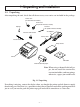
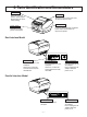
1. Unpacking and Installation 1-1. Unpacking After unpacking the unit, check that all the necessary accessories are included in the package.
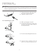
2. Parts Identification and Nomenclature Printer cover Front cover Open this cover to load or replace paper. Do not open the cover while printing. Push the center of the front cover to open the printer cover. Control panel Power switch Features LED indicators to indicate printer status and switches to operate the printer. Used to turn on/off power to the printer. Dual Interface Model USB interface RS-232 interface Power connector For connection to a host computer.
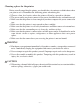
Choosing a place for the printer Before actually unpacking the printer, you should take a few minutes to think about where you plan to use it. Remember the following points when doing this. ✓ Choose a firm, level surface where the printer will not be exposed to vibration. ✓ The power outlet you plan to connect to for power should be nearby and unobstructed. ✓ Make sure that the printer is close enough to your host computer for you to connect the two.
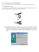
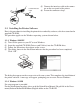
3. Setup 3-1. Connecting the Cable to the PC 3-1-1. USB Interface cable Connect the USB interface cable to a USB port of your PC. Note:The dialog shown below may appear on your PC screen if your PC is running Windows 98 or Me, and if you turn ON the power of the printer for the first time while the PC and the printer are connected with the USB cable. In this case, refer to the software manual on the CD-ROM, in the following directory: Documents folder. 3-1-2.
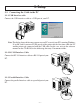
3-2. Connecting the Cable to the Printer Note that the interface cable is not provided. Please use a cable that meets specifications. 3-2-1. USB Interface Cable Affix the ferrite core onto the USB cable as shown in the illustration below and make sure to pass the cable through the cable support as shown in the illustration.
3-2-2. RS-232 Interface Cable (1) Make sure the printer is turn off. CAUTION Before connecting/disconnecting the interface cable, make sure that power to the printer and all the devices connected to the printer is turned off. Also make sure the power cable plug is disconnected from the AC outlet. (2) Connect the interface cable to the connector on the rear panel of the printer. (3) Tighten the connector screws. 3-2-3. Parallel Interface Cable Ferrite core (1) Make sure the printer is turn off.
Parallel interface cable (5) Connect the interface cable to the connector on the rear panel of the printer. (6) Fasten the connector clasps. 3-3. Installing the Printer Software Here is the procedure for installing the printer driver and utility software, which are stored on the supplied CD-ROM. The procedure applies to the Windows operating systems shown below. 3-3-1. Windows 2000/XP (1) (2) (3) (4) Turn ON the power to your PC to start Windows.
3-4. Connecting the AC Adapter Note:Before connecting/disconnecting the AC adapter, make sure that power to the printer and all the devices connected to the printer are turned off. Also make sure the power cable plug is disconnected from the AC outlet. (1) Connect the AC adapter to the power cable. Note:Use only the standard AC adapter and power cable. (2) Connect AC adapter to the connector on the printer. s (3) Insert the power cable plug into an AC outlet.
3-5. Turning Power On Make sure that the Power cord has been connected as described in 3-4. Turn ON the power switch located on the front of the printer. The POWER lamp on the control panel will light up. Power switch CAUTION We recommend that you unplug the printer from the power outlet whenever you do not plan to use it for long periods. Because of this, you should locate the printer so that the power outlet it is plugged into is nearby and easy to access.
3-6. Loading the Roll Paper 3-6-1. Thermal Label Roll Paper (Peel Mode) CAUTION When using a thermal label roll paper, do not install the tension bar, two tension folders, and two springs; otherwise, a paper jam could result. (1) Check that dip switch 1-8 is ON (default: thermal label roll paper). See Chapter 9 for instructions on how to set the dip switches. (2) Turn ON the power switch of the printer. (3) Push the front cover downward. (4) Open both the outer and inner printer covers.
(6) Peel off a label that is within 150 mm from the end of the roll paper, and place the roll paper in the direction shown. (7) Pull out the end of the backing paper towards you. (8) Close the inner cover, and firmly press both its ends.
(9) Turn the end of the backing paper backward. (10) Push both sides of the printer cover with your hands as shown, until the printer cover is securely closed. (11) Gently pull the end of the backing paper to take up the slack in the roll paper. (12) Press the FEED button to bring up the leading edge of the roll paper. Note: If the leading edge of a label is not detected after 300 mm or more of the roll is fed, the printer will determine that it is out of paper, and will stop.
3-6-2. Thermal Label Roll Paper (Tear Bar Mode) CAUTION When using a thermal label roll paper, do not install the tension bar, two tension folders, and two springs; otherwise, a paper jam could result. (1) Check that dip switch 1-8 is ON (default: thermal label roll paper). See Chapter 9 for instructions on how to set the dip switches. (2) Turn ON the power switch of the printer. (3) Push the front cover downward. (4) Open both the outer and inner printer covers.
(6) Peel off a label that is within 100 mm from the end of the roll paper, and place the roll paper in the direction shown. (7) Pull out the end of the backing paper towards you. (8) Check that the power switch is ON. (9) Leaving the backing paper as is, close both the outer and inner covers. Push both sides of the printer cover with your hands as shown, until the printer cover is securely closed. (10) Cut the portion of the backing paper, which extends from the front cover, along the tear bar.
(11) Press the FEED button to bring up the leading edge of the roll paper. Note: If the leading edge of a label is not detected after 300 mm or more of the roll is fed, the printer will determine that it is out of paper, and will stop. Redo the loading of the roll paper from the beginning. (12) The printer will eject a label as shown. 3-6-3. Thermal Roll Paper (1) Check that dip switch 1-8 is OFF (thermal roll paper). (2) Turn ON the power switch of the printer. (3) Push the front cover downward.
(6) If the thickness of the paper is 65 to 99 µm, install the tension bar on the printer as shown. If the thickness of the paper is 100 to 150 µm, it is not necessary to install the tension bar. Note: Firmly press the tension bar until it clicks into place. Click Note: To remove the tension bar, use a slot screwdriver to undo the clips at each end of the tension bar, as shown. Then, remove the tension bar. (7) Place the roll paper in the direction shown.
(8) Pull out the end of the roll paper towards you. (9) Leaving the paper as is, close both the outer and inner covers. Push both sides of the printer cover with your hands as shown, until the printer cover is securely closed. (10) Cut the portion of the paper that extends from the front cover. (11) Press the FEED button to bring up the leading edge of the roll paper.
WARNING • Do not touch the tear bar blade. - There is a tear bar blade inside the paper outlet slot. Not only should you not put your hand in the paper outlet slot while printing is in progress, never put your hand into the outlet even when printing is not in progress. Tear bar Tear bar • During and immediately after printing, the area around the thermal head is very hot. Do not touch it, as you could be burned.
4. Thermal Roll Paper Specification When consumable parts have run out, use those specified below. Note: Access the following URL for the information of the recommended paper. http://www.star-m.jp/eng/dl/dl02.htm 4-1. Thermal Label Roll Paper • Backing paper width: 45 ± 0.5 mm to 112 ± 0.5 mm • Paper thickness: 190 µm maximum • Roll paper outer dimensions Roll diameter: ø110 mm maximum roll diameter Overall width: 45 ± 0.5 mm to 112 ± 0.5 mm • Core inner/outer diameters: core inner diameter ø25.
• Recommended label paper: Thickness (µ m) Manufacturer Product name Lintec LD2114 Lintec Quality features/applications Base material Separator Total thickness Adhesion type High sensitivity, for handheld 65 50 115 High adhesion LD3330 High sensitivity, for distribution 87 65 152 High adhesion Lintec LD3180 High sensitivity, for distribution 82 65 147 Low adhesion Lintec LD9102 Virtual adhesive thermal 117 65 182 High adhesion Lintec LD5530 High sensitivity, for measurem
• Recommended label paper specifications: Use roll paper that meets the conditions below. Printing direction Base material (label paper) 4±1 A=36 to 304 (label pitch) 32 to 300 (label length) Peel paper (backing paper) 2 ± 0.5 41 to 108 ± 0.5 (label width) 45 to 112 ± 0.5 (backing paper width) (2) Unit: mm • Effective printing range: The printable range of label paper is shown below. 2.5 minimum (left margin) 103 (effective print width: 68 characters, using font A) {2.
• Black Mark Specifications (1) Black mark pitch Set the black mark pitch A to be within a range of 36 to 304 mm. (2) Black mark dimensions Set the black mark dimensions to be printed in accordance with the recommended black mark label paper specifications below. (3) PCS value Set the PCS value for the black mark to be printed to a minimum of 0.90.
(6) Effective printing range when using label paper with black mark specifications. 2.5 minimum (left margin) 103 (effective print width: 68 characters, using font A) {2.5 minimum (right margin)} A=36 to 304 (label pitch) 32 to 300 (label length) B=3+A×0.03 (bottom margin) 26 to 294 (effective printing length) 3 minimum (top margin) Effective print width Unit: mm 2 ± 0.5 41 to 108 ± 0.5 (label width) 45 to 112 ± 0.
4-2. Thermal Roll Paper • Paper width: 45 ± 0.5 mm to 112 ± 0.5 mm • Paper thickness: 65 µm to 150 µm • Roll paper outer dimensions Roll diameter: ø110 mm maximum roll diameter Overall width: 45 ± 0.5 mm to 112 ± 0.5 mm • Core inner/outer diameters: (1) When 65 µm paper thickness 75 µm core inner diameter ø12 ± 1/core outer diameter ø18 ± 1 or core inner diameter ø25.4 ± 1 mm/core outer diameter ø32 ± 1 mm (2) When 76 µm paper thickness 150 µm core inner diameter ø25.
5. Control Panel and Other Functions 5-1. Control Panel 3 FEED button 2 ERROR lamp (Red LED) 1 POWER lamp (Green LED) 1 POWER lamp (Green LED) Lights when the power is ON. 2 ERROR lamp (Red LED) Indicates various errors in combination with POWER lamp. 3 FEED button Press the FEED button to feed roll paper. 5-2. Errors 1) Automatically recoverable errors Error Description Head high temperature detection Cover open error POWER Lamp Flashes at 0.
2) Non-recoverable errors Error Description Head thermistor error POWER Lamp Off Power voltage error Off EEPROM error Off Flash access error Off SRAM error Off ERROR Lamp Flashes at 1.5-second intervals Flashes at 2-second intervals Recovery Conditions This is not a recoverable error. This is not a recoverable error. Flashes at 0.75-second in- This is not a recovertervals able error. Flashes at 0.5-second inter- This is not a recovervals able error.
5-4. Adjusting the Sensors This printer is equipped with three types of paper sensors. C B A Light Emitter A Light Receiver A. Label roll paper transmission type sensor This sensor detects the presence of the backing paper for the label roll paper. Because this sensor is affected by the thickness and the color of the backing paper of the label roll paper, the sensor might require an adjustment, depending on the label roll paper that is used. B.
(6) If the two lamps remain ON after flashing, it means that the sensor is adjusted properly and does not require further adjustment. (7) If both the ERROR and POWER lamps are OFF, use a plastic slot screwdriver to turn and adjust the VR3 knob to a position in which both the ERROR and POWER lamps are ON. If the adjustment has been successful, proceed to (10). (8) If the adjustment has not been successful, press the FEED button.
(5) Press and hold the FEED button, and turn ON the power switch of the printer. The two lamps will flash on the control panel to indicate that the sensor adjustment mode has been activated. After the lamps flash, release your finger from the button. (6) If the two lamps remain ON after flashing, it means that the sensor is adjusted properly and does not require further adjustment. Proceed to (8).
(6) After the lamps have flashed, turn the VR1 knob fully counterclockwise. The adjustment has been completed if the POWER lamp is ON. Proceed to (8). The ERROR lamp may be ON or OFF. (7) If the POWER lamp is not ON, turn and adjust the VR1 knob to a position in which both the ERROR and POWER lamps are ON. If the adjustment has been successful, proceed to (8). If the adjustment has not been successful, have the printer repaired. (8) Turn OFF the power switch and set the dip switch SW1-4 to ON.
6. Preventing and Clearing Paper Jams 6-1. Preventing Paper Jams The paper should not be touched during ejection and printing. Pressing or pulling the paper during ejection may cause a paper jam or line feed failure. 6-2. Removing Paper Jam If a paper jam occurs, clear it as described below. (1) Set the power switch to off to turn off power to the printer. (2) Push the front cover and open the printer cover. (3) Remove the jammed paper.
7. Periodic Cleaning At times, the printer might leave some characters partially unprinted due to paper particles or debris from the adhesive used on label paper. As a preventive measure, clean the printer regularly every month or after printing 200,000 lines. 7-1. Cleaning the Thermal Head and Ground Hardware Use the optional head cleaner as shown to remove the grime from the thermal head.
8. Specifications 8-1. General Specifications (1) (2) (3) (4) (5) Printing method Print speed Dot density Printing width Roll paper (6) Overall dimension (7) Weight (8) Noise Approx. Direct line thermal printing Max. 150 mm/sec. 203 dpi: 8 dots/mm (0.125 mm/dot) Max. 104 mm Refer to chapter 4 for details on the recommended roll paper. Paper width:44.5 ± 0.5 mm to 111.5 ± 0.5 mm (thermal roll paper) 43 ± 0.5 to 110 ± 0.
8-2. Interface • Bidirectional parallel interface: IEEE 1284 compatibility and nibble modes • Dual interface: RS-232 D-Sub 9 pin USB USB type-B connector 8-3. Electrical Characteristics (1) Input: 100 to 240V AC, 50/60 Hz (2) Output: DC 24V ± 5% (3) Current Consumption Operating: Approx. 2.0 A (at ASCII printing) Approx. 10 A (at print duty 100%, for 10 seconds or less) Peak: Stand-by: Approx. 0.1 A (4) Power Connector Pin No. 1 2 3 Shell Function Drive power (24V) Signal GND N.C.
8-4. Environmental Requirements (1) Operating Temperature Humidity 5°C to 45°C 10% to 90% RH (without condensation) (%RH) 34°C 90% RH 90 Relative humidity 80 40°C 65% RH 60 45°C 50% RH 40 Operating environment range 20 10 0 10 20 30 40 50 Temperature (°C) Operating temperature and humidity range (2) Transport/storage (except for paper) Temperature -20°C to 60°C Humidity 10% to 90% RH (without condensation) 8-5.
9. Dip Switch Setting Two DIP switches are provided at the bottom of the printer, and can be set as given in the table below. Be sure to set the power switch to off before changing the settings. It is recommended to use a pointed item like a pen or flat-blade driver screw to change the settings. The settings will become effective when the power switch is set to on again. The following is the procedure for changing the settings on DIP switches. 1. Make sure the printer is turned off. 2.
9-1. Parallel Interface Type ON ON OFF OFF No. 1 2 3 4 5 6 7 8 No.
9-2. Dual Interface Type The dual interface enables the connection of an RS-232 interface and a USB interface, although they cannot be connected concurrently. The printer starts with the RS-232 interface at the time its power is turned ON. Afterwards, it will switch automatically to the USB interface if a USB cable that is connected to a computer is connected to the dual interface.
DIP-SW 2 Switch 2-1 2-2 2-3 2-4 Function ON Always ON OFF Should be set to on The factory settings of DIP switch are all on. 9-2-2. RS-232 Interface Type ON OFF ON OFF No. 1 2 3 4 5 6 7 8 No.
DIP-SW 2 Switch 2-1 2-2 2-3 2-4 Function ON Always ON OFF Should be set to on ■ DIP Switch 3 The factory settings of DIP switch are all on. The following is the procedure for changing the settings on DIP switch No. 3. 1. Turn off the printer and all components connected to it. 2. Remove the 2 screws. 3. Remove the dual interface board unit. 4. Change the setting of the DIP switches. 5. Replace the dual interface board unit. 6. Then secure it with the screws. 7.
DIP-SW 3 Switch 3-1 3-2 3-3 3-4 3-5 3-6 3-7 3-8 Baud Rate 4800BPS 9600BPS 19200BPS 38400BPS Function ON Baud Rate OFF See table below Data Length Parity Check Parity Handshake 8 bits Disabled Odd DTR 7 bits Enabled Even XON/XOFF Should not be changed (Should be set to off) — — Switch 3-1 OFF ON ON OFF Switch 3-2 ON ON OFF OFF – 41 –
10. Parallel Interface The two-way parallel interface is compatible with the IEEE1284 compatibility mode and nibble mode. Refer to the separate specification manual for details. Table of Connection Signals for Each Mode Pin No.
11. Dual Interface 11-1. RS-232 Interface 11-1-1. Interface Specifications 1 Data transmission method: 2 Baud rate: 3 Word length 4 Signal polarity Asynchronous serial interface Selectable from 4800, 9600, 19200, 38400 bps (Refer to “9. DIP Switch Setting”.) Start bit: 1 bit Data bit: 7 or 8 bits (selectable. Refer to “9. DIP Switch Setting”.) Parity bit: Odd, even or none (selectable. Refer to “9. DIP Switch Setting”.
11-1-2. Connectors and Signal Names RS-232 Pin No. – 1 2 3 4 Signal name FG N.C RXD TXD DTR Direction — — IN OUT OUT 5 6 7 8 9 S-GND DSR RTS CTS N.C — IN OUT IN — Function Frame ground Not used Receiving data Transmission data Indicates whether data receive from host is enabled or disabled. 1) DTR Communication Mode Space when receive is enabled.
11-1-3. Cable Connections The followings are a recommended interface cable connections. Printer side (D-sub 9 pin) NC 1 RXD 2 TXD Host side 9 pin 25 pin 1 FG 2 3 RXD 3 3 2 TXD DTR 4 7 4 RTS SG 5 5 7 SG DSR 6 8 5 CTS RTS 7 6 6 DSR CTS 8 1 8 DCD NC 9 4 20 DTR Note: Use shielded wire less than 3 m in length. 11-2. USB Interface 11-2-1. USB Function 1. 2. 3. 4. General Specification: Conforms to USB 2.
12. Memory Switch Settings Each memory switch is stored in EEPROM. For details on the functions and settings of memory switches, see the separate Specification Manual. The table below shows the factory settings for the memory switches. Memory Switch 0 1 2 3 4 Hexadecimal Code 0000 0000 0000 0000 0000 Warning! Changing the memory switch settings can cause the printer to fail to operate correctly.
ELECTRONIC PRODUCTS DIVISION STAR MICRONICS CO., LTD. OVERSEAS SUBSIDIARY COMPANIES STAR MICRONICS AMERICA, INC. 536 Nanatsushinya, Shimizu-ku, Shizuoka, 424-0066 Japan Tel: 0543-47-0112, Fax: 0543-48-5013 1150 King Georges Post Road, Edison, NJ 08837-3729 U.S.A. Tel: 732-623-5555, Fax: 732-623-5590 Please access the following URL http://www.star-m.jp/eng/dl/dl02.htm for the latest revision of the manual. STAR MICRONICS U.K. LTD.