
User's Manual


MovingMedia 2000 iCell Pico BTS Installation Guide Page 13 of 16
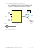
Perform the wall mounting. Mark the location of the drilling holes according to Figure
3-4. Drill three holes
Hang the Mounting Bracket in the marked location and fasten with three screws.
Mount the Power Supply onto the Wall Mount Bracket. Assemble the iCell unit to the
bracket on the spacers. Connect a BTS module according to section 3.4.2.
Figure 3-4: Hole Location for Mounting Bracket
To comply with Maximum Permissible Exposure (MPE) requirements, the maximum composite
EIRP output from the antenna cannot exceed 1.26 Watts EIRP and the antenna must be
permanently installed in a fixed location that provides at least 13 cm of separation from all persons.
This is maximum separation based on the possibility of connecting the Pico to a very high gain
directional antenna of 11 dBi. A more typical 3 dBi gain antenna would result in a separation
distance of 5 cm.
3.4 Interface Connections
3.4.1 BTS Interface Connections
Verify that the power switch is off and the external AC power line is
disconnected.
3.4.2 BTS Interface Connection
Figure 3-7 illustrates the wiring diagram of the wall mount configuration and Table 3-4
provides the wiring parameters.
130.0 cm (5.12")