V-bike® Spinner® Spinner® Pro Spinner® Elite Spinner® NXT OWNER’S GUIDE
Introduction . . . . . . . . . . . . . . . . . . . . . . . . . . . . . . . . . . .. . . . . . . . . . . . . . . . . . . . . . . . . . . . . . . . . . . . . . . . . . . . . . . Safety Instructions . . . . . . . . . . . . . . . . . . . . . . . . . . . . . . . . . . . . . . . . . . . . . . . . . . . . . . . . . . . . . . . . . . . . . . . . . . . . Assembly and Setup . . . . . . . . . . . . . . . . . . . . . . . . . . . . . . . . . . . . . . . . . . . . . . . . . . . . . . . . . . . . . . . . . . . . . . . . .
INTRODUCTION _ Welcome to the world of STAR TRAC®. This manual will acquaint you with the assembly, operation and maintenance of your STAR TRAC group cycle.
SAFETY INSTRUCTIONS _ INSTRUCTIONS The following fitness safeguards and operating precautions are directed to purchasers and users of STAR TRAC group cycles. Club Managers should ensure that members and fitness staff are trained to follow these same instructions. Failure to follow these safeguards may result in injury or serious health risk. FITNESS SAFEGUARDS • • • • Make your physician aware of any proposed fitness regimen before embarking on any exercise program.
ASSEMBLY AND SETUP _ ASSEMBLY AND SETUP V-BIKE® SPINNER® ASSEMBLY AND SETUP Use the following procedures to unpack and assemble your STAR TRAC V-BIKE SPINNER. UNPACKING Position the shipping carton so the “Heavy End” logo is located at the bottom. Open the top of the carton and fold back all four flaps. Carefully tilt the box forward so that the box may be lifted to expose the cycle.
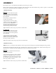
ASSEMBLY 1. Install the Back Leg Place the back leg in position at the rear of the cycle, aligning the two holes in the leg with the mating holes in the frame bracket. Insert two 8mm x 70mm bolts through the frame bracket and back leg, and install a flat washer and nut on each bolt. Using the #5 Allen Wrench and Multi-Purpose Wrench, tighten the nuts securely. Step 1 2.
5. Install the Handlebar Insert the handlebar post into the frame assembly and secure in place using a tension handle. Position the handlebar on top of the handlebar post and secure in place using a tension handle and washer. NOTE: Tighten the tension handles firmly. Step 5 6. Install the Water Bottle Holders Using the Allen Wrench, remove the two screws from the right side fork of the frame assembly.
SPINNER® PRO / ELITE / NXT ASSEMBLY AND SETUP Use the following procedures to unpack and assemble your STAR TRAC SPINNER ®. UNPACKING Prepare the area that you will be unpacking and assembling the bike to be free from debris that may cause damage. Observe all safety precautions and care while unpacking and assembling the bike. Position the shipping carton so the “Heavy End” logo is located at the bottom. Open the top of the carton and fold back all four flaps.
Take time now to enter your V-bike® Spinner® serial number in the space below (serial number is located on the bottom cross member). If parts are missing, or if you have any operational questions, please call Star Trac’s Service department at (800) 5031221; have your serial number ready. Serial No._____________________________________________ NOTE: If you are missing any of the parts listed above, inspect the packing material and the box for items that may have been overlooked.
ASSEMBLY Following these steps in order will minimize the build time and ensure proper assembly. Note: Not all of the following procedures are performed on all models; Spinner ® Pro, Elite and NXT. If the procedure is specific to a model it will be noted as follows: NXT Only, Pro/Elite Only, NXT/Elite Only, or Pro Only. 1. Install the Back Leg NXT Only Lift up the rear of the bike frame and place the rear leg assembly in position under the frame, aligning the holes in the leg with the holes in the frame.
Pro & Elite Only Using the 5mm hex wrench and a 13mm combination wrench insert 2- M10X55mm flat head screws, nuts and washers to secure the front leg assembly to the frame. Tighten all screws/nuts securely using a torque wrench to 85 Inch Pounds Step 2 (Pro/Elite) Move the bike to a flat surface and adjust the four leveling feet so the bike is stable. 3. Install the Saddle and Seat Slider Install the seat post into the frame and lower it to the lowest position and tighten the pop pin securely.
5. Install the Handlebar NXT Only Positioning the handlebar post with the number 1 on top and insert the handlebar into the handlebar sleeve locking it at number 4. Slide the handlebar onto the handlebar post insert with the water bottle holders facing forward and align the three screw holes. Insert the socket head set screw into the handlebar but do not tighten at this time. Insert the 2 flat head screws into the handlebar but do not tighten at this time.
You have now completed the assembly of your STAR TRAC SPINNER® PRO / ELITE / NXT SPINNER PRO SPINNER ELITE SPINNER NXT Testing the Bike Use this checklist to perform the bike test procedure. Recheck all the bolts and make sure they are all tightened to the proper torque specification and no parts are missing. Test the handlebar and seat post to make sure they move freely and you are able to lock in at different positions.
INSTRUCTIONS FOR USE _ Your STAR TRAC group cycle is easy to use. Simply sit on the cycle, tighten the pedal straps and begin pedaling. The cycle allows the user full control over resistance by simply adjusting the brake pad. Typically, lower resistance levels enable you to pedal at a faster pace, placing increased demand on the cardiovascular system. Higher resistance levels will typically deliver a greater muscle/endurance workout at lower RPMs.
HANDLEBAR ADJUSTMENTS Proper position for the handlebar is based primarily on comfort. Typically, the handlebar should be positioned slightly higher than the seat. All group cycles allow for adjustment of handlebar height. Additionally, the V-bike® Spinner® allows for fore andaft adjustment of the handlebar. To adjust the handlebar height: (V-bike® Spinner®) Loosen the handlebar height tension handle by turning the handle counterclockwise.
TRAINING INFORMATION _ This section provides hints on how to stay motivated, and suggestions for getting the most out of your workouts with maximum ease, efficiency and enjoyment. IMPORTANT: User should be aware of the features, functions and proper operation of the cycle before using the cycle for the first time. BEFORE BEGINNING Be sure the seat, handlebar and pedal straps are properly adjusted for your body size and comfort before beginning your workout.
MAINTENANCE _ This section provides the procedures to maintain the group cycles in serviceable condition. Differences between models are noted where applicable. PREVENTIVE MAINTENANCE Perform regular scheduled preventive maintenance procedures to maintain your group cycle in serviceable condition. ATANCE TOOLS Tools required for service and maintenance of your group cycle are listed below.
IMPORTANT: If your facility allows members to interchange pedals, it is critical that the pedals are checked after each class to prevent damage, which may lead to injuries if ignored. Water bottle (V-bike & Spinner Pro) Tighten down assembly screws. NOTE: Water bottle cages are easily damaged when oversized bottles are forced to fit within the bottle cage. Checking and tightening the screws will help prevent damage.
MOVING AND LEVELING To move the cycle to a new location: Lift the cycle from the rear and use the front wheels (located on the front leg, below the handlebar) to roll the cycle from one location to another. To level the cycle: Use the four leveling adjusters (located on the underside of the front and rear legs) to compensate for uneven floor surfaces. PARTS REPLACEMENT BRAKE PAD REPLACEMENT Removal 1.
Chain tension adjustment NXT PRO/ ELITE 1. Using the 16mm or 5/8” socket and socket wrench loosen the axle nuts on the sides of the flywheel. 2. Using the 10mm open end wrench, loosen the lock nuts on the chain adjustment screws. 3. To tighten the chain, turn the adjustment screw in a clockwise rotation equally on both sides using the 10mm open end wrench. 4. To loosen the chain turn the adjustment screw counter clockwise rotation (unscrew) equally on both sides using the 10mm open end wrench. 5.
Chain Replacement CAUTION: Do not get your fingers caught in the chain or sprockets. 1. Remove the chain guard by unscrewing the chain guard screws. 2. Apply tension to the brake knob by turning it all the way clockwise so the flywheel does not turn. NXT PRO/ ELITE 3. Using the 16mm or 5/8” socket and socket wrench loosen the axle nuts on the sides of the flywheel. 4. Using the 10mm open end wrench, loosen the lock nuts on the chain adjustment screws. 5.
STAR TRAC 14410 Myford Road Irvine, California 92606 Telephone: (800) 228-6635, (714) 669-1660 Fax: (714) 508-3303 http://www.startrac.com c Part Number 620-7302, Rev.