STAR TRAC 14410 Myford Road Irvine, CA 926060 USA WORK INSTRUCTIONS, E-TBT / E-TBTe INSTALLATION 2 620-7921 Rev A
GENERAL Before using this product, it is essential to read ALL installation Instructions and this ENTIRE operations manual; the manual describes equipment setup and instructs members on how to use it correctly and safely. TOOLS REQUIRED 1. Phillips screwdriver, #2 (Included) 2. Hex (Allen) key, 3/16 (Included) 3. Hex (Allen) key, 16” (Included) 4. Hex (Allen) key, 5MM (Included) 5.
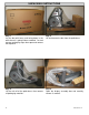
UNPACKING INSTRUCTIONS Step 1. Lay the box with heavy end facing down in the area where it is going to be assembled. Cut and remove packaging straps then open and remove the top cover. Step 2. Lift and remove the box from the pallet base. Step 3. Lift the unit off of the pallet base, then remove all packaging materials. Step 4. Open the display assembly box and carefully remove its content.
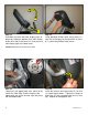
Step 5. Remove remaining packaging materials and lay all components on the floor. 1 Step 6. Verify the following components are included in the package: 1. TBT frame. 2. Display console assembly. 3. Upper neck. 4. Left and right upper body arms. 5. Owner’s manual, installation manual and warranty registration card. 6. Hardware kit. 5 2 6 4 3 1 2 3 1 2 3 4 5 4 Step 7.
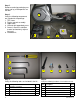
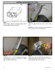
INSTALLATION INSTRUCTIONS Step 1. Route display cables up through upper half of neck through the holes provided. Step 2. Insert the upper half of the neck into the lower half. Caution: Be careful not to pinch any cables between the two sections of the assembled neck. Step 3. Install two 5/16” - 18 X 3/4” button head screws into front neck using a 3/16” hex key. Tighten bolts to 200 in-lbs (23 N-m). 6 Step 4. Secure the neck by tightening the 3/8-16 x 2” socket head cap screw using a 5/16” hex key.
Step 5. Using provided screwdriver, remove the M4 x 0.7 screws that hold the display assembly together, then separate the back of the display from the front. Note: Retain the screws for later use. Step 7. Line up the four holes of the mounting bracket with holes of the neck, then insert four 6mm x 50mm socket head cap screws. 7 Step 6. Slide the back of the display with the mounting bracket onto the upper neck of the Total Body Trainer.
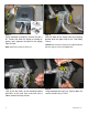
3 2 1 4 Step 9. Identify the four cables coming out of the neck and mounting bracket: 1. Heart rate cable 2. Main I/O cable 3. Coax cable 4. DC power cable Step 10. Plug-in the 12-pin main I/O cable into the front display circuit board at J4 connector. Note: If the unit is not equipped with Personal Viewing Screen, the coax and DC power cables should be tucked down the neck as they are part of the PVS Kit. Step 11. Next, plug-in the heart rate cable into the HR board connector. 8 Step 12.
2 1 Step 13. Assemble the front and back display parts together by sliding the bottom of the front display under the 2 tabs at the base first, then pressing front display against the back cover. Step 14. Using provided Phillips head screw driver, secure the front display to the back with (8) M4 x 0.7 x 19mm long Phillips head screws. Caution: Be careful not to pinch any wires. Step 15. Locate left side upper body arm, move to left side of the Total Body Trainer.
Step 17. Place the Total Body Trainer on the floor in the position it will be used. Then adjust leveling feet to assure that the Total Body Trainer is leveled to the floor and does not rock back and forth. Step 18. Perform a visual inspection, and test the features and functions of the unit prior to use. Note: Refer to the User’s Manual for other settings and instructions.
Use the checklist below to ensure the proper installation of the Total Body Trainer: 1. All parts, tools and hardware in the package are accounted for. 2. All screws are tightened and torqued down to their specified values. 3. Upper body arms are properly mounted and secured. 4. Upper body arms move freely, along the entire range of motion. 5. Upper neck is properly mounted and secured. 6. Display’s mounting bracket and back cover are properly mounted and secured. 7.
EMBEDDED DISPLAY CONSOLE INSTALLATION INSTRUCTIONS 1 2 3 1 2 4 3 5 Step 1. Remove all contents from the packaging and verify that you have the following parts: 1. Embedded display console. 2. Operation manual. 3. Tool kit. 4. Power adaptor (60W AC). 5. Power cord. Step 2. Verify the tool kit has the following parts: Step 3. Be careful with the display and place it face down on top of a non-scratching surface to protect it from being damaged. Step 4.
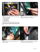
Step 5. Disconnect the ground cable from the ground quick disconnect tab on the embedded display. Save the cable for later use. Step 6. Mount the back cover to the display mounting bracket using four (4) M4 x 0.7 x 19mm long Phillips head screws and four (4) M4 flat washers. Step 7. Attach the ground cable to upper left screw on the mounting bracket and secure tightly. Step 8. Pullout the coax adapter from the tuner card on the embedded display.
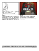
After Before Step 9. Now screw in the coax adaptor to the coax cable coming out of the base neck. Step 10. Go back to the embedded display assembly and remove the plastic tabs from the lower back cover. 3 2 1 Step 11. Take the embedded display assembly to the base unit. Hold the front display plastics at the top with one hand while connecting the cables and harnesses with the other. 14 4 Step 12. Identify the four cables coming out of the neck and mounting bracket: 1. Heart rate cable 2.
Step 13. Plug-in the heart rate cable from the neck into the heart rate board connector on the FitCPU board of the embedded display assembly. Step 14. Plug-in the 12-pin main I/O cable from the neck to the 12 pin connector on the FitCPU board of the embedded display assembly. Step 15. Next plug in the coax cable to the coax adapter on the tuner card of the embedded display assembly. Step 16. Now plug in the DC power cable from the base neck to DC connectors on the embedded display assembly.
Step 17. Plug in the Heart rate ground cable into the quick disconnect tab on the display mount. Step 18. Plug in the ground cable coming from upper left side of the display mounting bracket into the quick disconnect tab on the embedded display assembly. 2 1 Step 19. Assemble the front and back display parts together by sliding the bottom of the front display under the 2 tabs at the base first, then pressing front display against the back cover. Step 20.
Step 21. Now it is time to connect entertainment cable and power to the unit. Connect the in-house entertainment cable to the RF input at the base of the unit. Take the power supply from the kit and plug the small barrel connector to the DC input. Then take the power adapter cable from the kit and plug it into the power supply and the electrical receptacle. Step 22. Turn power on. Perform a visual inspection, and test the features and functions of the unit prior to use.
Use the checklist below to ensure the proper installation of the Total Body Trainer: 1. 2. 3. 4. 5. 6. 7. 8. All parts and hardware in the package are accounted for. Embedded display assembly is clear of any scratches or damage. All screws are tightened and torqued down to their specified values. Display’s mounting bracket and back cover are properly mounted and secured. All cables and harnesses are properly plugged to their respective connectors.
iPod® CENTER CONSOLE INSTALLATION INSTRUCTIONS 1 3 2 5 1 2 4 Step 1. Remove all contents from the packaging and verify that you have the following parts: 1. iPod® center console. 2. iPod® cradle. 3. Owner’s manual. 4. Cable kit. 5. Lower back cover. Step 2. Verify the cable kit has the following two parts: 1. Center console power cable. 2. Headphone jack and mount.
Step 5. Disconnect the ground wire between the heart rate board and the display mount. Step 6. Disconnect the 12-pin serial connector from the display Step 7. Now disconnect the heart rate connector from the display Step 8. Be careful with the display and place it face down on top of a non-scratching surface to protect it from being damaged.
Step 9. Using a #2 Phillips head screwdriver, remove the (4) screws that hold bottom side of the display console on, then remove the (1) screw that holds the headphone jack cap. Step 10. Next remove the bottom cover, then remove the headphone blank cover. You will no longer need those covers and they can be stored away for any possible future use. Note: Retain screws for later use. Step 11.
2 1 3 4 Step 13. Now install the new head phone jack mount. Use the screw saved from the earlier step to secure the mount to the display. Step 14. Identify the cables coming out of the new center console: 1. Center console keypad ribbon cable. 2. Headphone jack cable. 3. Center console ground cable. 4. Seven-pin interface cable. Step 15. Connect the center console keypad cable to J8 connector on the display board. Step 16.
Step 17. Take the headphone jack cable from the center console and connect it to the newly installed headphone jack in the front of the display. Step 18. Take the center console power cable from the kit, attach the male 12 pin connector to the female 12 pin connector on the display board. Then connect the (2) DC power connectors to the center console. Note: The DC power cables can be plugged to either one of the DC connectors on center console. Step 19.
Before After Step 21. Take the new bottom cover and remove the handlebar plastic tabs. Step 22. Slide off and remove the CSAFE power connector from the old bottom plastic cover. Step 23. Install the CSAFE power connector on the new bottom plastic cover. Step 24. Install the new bottom plastic cover onto display, use the screws saved from the earlier step to secure the display bottom. Tighten the screws so they are snug. Note: Take special care to not pinch any of the cables between the plastics.
Step 25. Connect the CSAFE power cable from the bottom cover to J10 connector on the display board. Step 26. Take the front display plastics with the new center console to the base unit. Hold the front display plastics at the top with one hand while connecting the cables and harnesses with the other. 3 2 1 4 Step 27. Identify the four cables coming out of the neck and mounting bracket: 1. Heart rate cable 2. Main I/O cable 3. Coax cable 4. DC power cable Step 28.
Step 29. Next, plug-in the heart rate cable from the neck into the heart rate board connector on the display. Step 30. Plug back the Heart rate ground cable into the quick disconnect tab on the display mount. 2 1 Step 31. Plug the center console ground cable into the quick disconnect tab on the display mount. Step 32. Assemble the front and back display parts together by sliding the bottom of the front display under the 2 tabs at the base first, then pressing front display against the back cover.
Step 33. Using a Phillips head screw driver, secure the front display to the back with (8) M4 x 0.7 x 19mm long Phillips head screws. Step 34. Turn power on. Perform a visual inspection, and test the features and functions of the unit prior to use. Note: Refer to the User’s Manual for other settings and instructions.
Use the checklist below to ensure the proper installation of the Total Body Trainer: 1. 2. 3. 4. 5. 6. 7. All parts, tools and hardware in the package are accounted for. Center console assembly is properly mounted and secured. All screws are tightened and torqued down to their specified values. Display’s mounting bracket and back cover are properly mounted and secured. All cables and harnesses are properly plugged to their respective connectors.
MYE® ENTERTAINMENT CENTER CONSOLE INSTALLATION INSTRUCTIONS 1 3 2 4 5 Step 1. Remove all contents from the packaging and verify that you have the following parts: 1. MYE® center console. 2. iPod® cradle. 3. iPod® center console owner’s manual. 4. MYE® operation manual. 5. Lower back cover. Step 2. Using a #2 Phillips screwdriver, remove the (8) screws on the back of the display plastic. Set the screws aside, you will need them for reassembly.
Step 5. Disconnect the 12-pin serial connector from the display Step 6. Now disconnect the heart rate connector from the display Step 7. Be careful with the display and place it face down on top of a non-scratching surface to protect it from being damaged. Step 8. Using a #2 Phillips head screwdriver, remove the (4) screws that hold bottom side of the display console on, then remove the (1) screw that holds the headphone jack cap. Note: Retain screws for later use.
Step 9. Next remove the bottom cover, then remove the headphone blank cover. You will no longer need those covers and they can be stored away for any possible future use. Step 10. Using a Phillips head screwdriver, remove the (4) screws that hold the original center console in place, then remove the center console. You will no longer need the center console and it can be stored away for any possible future use. Step 11. Insert the new center console into the front display.
2 1 3 4 Step 13. Identify the cables coming out of the new center console: 1. Center console keypad ribbon cable. 2. Center console power cable 3. Center console ground cable. 4. Seven-pin interface cable. Step 14. Connect the center console keypad cable to J8 connector on the display board. Step 15. Connect the seven-pin interface cable from the console to J14 connector on the display PC board. Step 16.
Step 17. Take the new iPod® cradle from the kit and install it onto display console. Before After Step 19. Take the new bottom cover and remove the handlebar plastic tabs. 33 Step 18. Now connect iPod® cable from the iPod cradle to J10 connector on the center console board. Step 20. Slide off and remove the CSAFE power connector from the old bottom plastic cover.
Step 21. Install the CSAFE power connector on the new bottom plastic cover. Step 22. Install the new bottom plastic cover onto display, use the screws saved from the earlier step to secure the display bottom. Tighten the screws so they are snug, then plug in the CSAFE power cable to the back of the display. Note: Take special care to not pinch any of the cables between the plastics. 3 2 1 Step 23. Take the front display plastics with the new center console to the base unit.
Step 25. Plug-in the 12-pin main I/O cable from the neck to the new 12 pin adaptor. Step 26. Next, plug-in the heart rate cable from the neck into the heart rate board connector on the display. Step 27. Plug back the Heart rate ground cable into the quick disconnect tab on the display mount. Step 28. Plug the center console ground cable into the quick disconnect tab on the display mount.
2 1 Step 29. Assemble the front and back display parts together by sliding the bottom of the front display under the 2 tabs at the base first, then pressing front display against the back cover. Step 30. Using a Phillips head screw driver, secure the front display to the back with (8) M4 x 0.7 x 19mm long Phillips head screws. Caution: Be careful not to pinch any wires. Step 31. Turn power on. Perform a visual inspection, and test the features and functions of the unit prior to use.
Use the checklist below to ensure the proper installation of the Total Body Trainer: 1. 2. 3. 4. 5. 6. 7. 8. All parts, tools and hardware in the package are accounted for. Center console assembly is properly mounted and secured. All screws are tightened and torqued down to their specified values. Display’s mounting bracket and back cover are properly mounted and secured. All cables and harnesses are properly plugged to their respective connectors.
PERSONAL VIEWING SCREEN (PVS) INSTALLATION INSTRUCTIONS 2 1 1 4 3 2 5 6 3 4 5 6 7 7 Step 1. Step 2. Remove all contents from the packaging and verify that you have the following parts: Remove all content from the hardware kit packaging and verify that you have the following parts: Item 1 2 3 4 5 6 7 Description PVS assembly with mounting bracket. Headphone jack and mount. PVS center console. Owner’s manual with registration card. Power adaptor. Hardware kit. Power cord.
Step 5. Disconnect the ground wire between the heart rate board and the display mount. Step 6. Disconnect the 12-pin serial connector from the display. Step 7. Now disconnect the heart rate connector from the display. Step 8. Be careful with the display and place it face down on top of the non-scratching surface.
Screws Screws Step 9. Remove the cap cover with the Star Trac logo from the back cover plastics by removing the (2) screws using a #2 Phillips screwdriver. Retain screws for later use. Note: You will no longer need the cap cover and, if desired, you can store it away for any possible future use. Step 11. Mount the PVS assembly on the mounting bracket, then thread the (4) M8 buttonhead screws through the PVS mounting bracket into the display mount. Do not tighten the screws yet. 40 Step 10.
Step 13. Using a #2 Phillips head screwdriver, remove the (4) screws that hold the bottom cover of the display console, then remove the (1) screw that holds the headphone jack cap. Note: Retain screws for later use. Step 15. Using a Phillips head screwdriver, remove the (4) screws that hold the original center console in place, then remove the center console. Step 14. Next remove the bottom cover, then remove the headphone blank cover.
Step 17. Install the iPod® cable into the iPod® cradle on the front side of the display console by removing the plug from the cradle then inserting the cable through opening. Make sure cable is aligned properly with the display plastics. Press firmly to insure the cable is seated into the cradel. Step 18. Tie the iPod® cable to the plastic using the 3.5” tie wrap. 2 1 Step 19. Now install the new head phone jack mount. Use the screw saved from the earlier step to secure the mount to the display.
Step 21. Connect the center console keypad cable to J8 connector on the display board. Step 22. Connect the seven-pin interface cable from the console to J14 connector on the display board. Step 23. Now connect the iPod® cable from the bottom cover to J10 connector on the center console board. Step 24. Next replace the bottom cover. Use the screws saved from the earlier step to secure the display bottom. Tighten the screws so they are snug, then plug in the CSAFE power cable to the back of the display.
3 2 1 Step 25. Take the front display plastics with the new center console to the base unit. Hold the front display plastics at the top with one hand while connecting the cables/harnesses with the other. 4 Step 26. Identify the four cables coming out of the neck and mounting bracket: 1. Heart rate cable 2. Main I/O cable 3. Coax cable 4. DC power cable From PVS Neck 1 2 3 4 5 6 From Base Neck Step 27. Identify the cables coming out of the PVS neck: 1. Coax cable. 2. Headphone jack cable. 3.
Tie Wrap Step 29. Take the 5” piece of tape from the PVS kit and wrap the connectors so that all of the metal surface is covered. Step 30. Using a 5” tie wrap from the PVS kit, bind the cables from the PVS neck to one side of the display mount. Take the tie and put it through the hole on one of the display mount tubes. Step 31. Plug-in the 12-pin main I/O cable coming from the unit base into the front display circuit board at J4 connector. Step 32.
Step 33. Plug the DC power cable from the base neck to either one of the DC connectors on new center console board. Then plug the DC power cable from the PVS neck to the other DC connectors on same center console board. Step 34. Plug the data interface cable coming from the PVS neck into the center console board. Step 35. Plug the video cable coming from the PVS neck into the center console board. Step 36. Plug the audio cable coming from the PVS neck into the center console board.
Step 37. Plug back the Heart rate ground cable into the quick disconnect tab on the display mount. Step 38. Plug the center console ground cable into the quick disconnect tab on the display mount. 2 1 Step 39. Plug the headphone jack cable coming from the PVS neck into the, newly installed, headphone jack on the front of display. Step 40.
Step 41. Using a Phillips head screw driver, secure the front display to the back with (8) M4 x 0.7 x 19mm long Phillips head screws. Step 42. Now it is time to connect entertainment cable and power to the unit. Connect the in-house entertainment cable to the RF input at the base of the unit. Take the power supply from the kit and plug the small barrel connector to the DC input. Then take the power adapter cable from the kit and plug it into the power supply and the electrical receptacle. Step 43.
Use the checklist below to ensure the proper installation of the Total Body Trainer: 1. All parts, tools and hardware in the package are accounted for. 2. Personal Viewing Screen assembly is properly mounted and secured. 3. Center console assembly is properly mounted and secured. 4. All screws are tightened and torqued down to their specified values. 5. Display’s mounting bracket and back cover are properly mounted and secured. 6. All cables and harnesses are properly plugged to their respective connectors.
STAR TRAC 14410 Myford Road Irvine, California 92606 Telephone: (800) 228-6635, (714) 669-1660 Fax: (714) 508-3303 http://www.startrac.
Star Trac Fitness TM E-TBT Total Body Trainer OWNER’S MANUAL
MANAGER / MAINTENANCE MODE After using your STAR TRAC E SERIES TOTAL BODY TRAINERS for a period of time, you may wish to change some of its settings. MANAGER MODE The Manager Mode allow you to query and modify the basic settings of your Total Body Trainer. To enter Manager Mode: 1. Press and hold the , and keys together. 2. A beep will sound and “MANAGER MODE” will display momentarily in the Message Window. 3. Release all keys. “SERIAL NO #####” will display in the Message Window.
The following keys are available in MAINTENANCE MODE: Upper and Lower Data Information Window SCROLL Keys: Display the next and previous parameters, respectively. Keys will repeat if held. Increase and Decrease LEVEL Keys: Adjust the value of the displayed parameter up and down, respectively, in increments of 1 unit . These keys do not save the new value - see OK Key below. OK Key: Updates (saves) the values of all parameters in Flash memory, and exits Maintenance Mode.
Lowest Value Highest Value Default Value CW Prog 0 65535 0 Number of times the Continuous Watts Program was run since last reset. Alpine 0 65535 0 Number of times the Alpine Pass Program was run since last reset. Rndm Prog 0 65535 0 Number of times the Random Hill Program was run since last reset. UB Revs 0 65335 0 Number of times the upper body system completed a full revolution. Comm Lost 0 65535 0 Number of times a “Communication Lost” condition occurred since last reset.