LEG CURL IP-S1315 INSTALLATION INSTRUCTIONS
Copyright 2009. Star Trac by Unisen, Inc. All rights reserved, including those to reproduce this book or parts thereof in any form without first obtaining written permission from Star Trac. Every effort has been made to keep this information current; however, periodically, changes are made to the information herein, and these changes will be incorporated into new editions of this publication. All product names and logos are trademarks of their respective owners. Printed in the USA.
INSTALLATION INSTRUCTIONS REQUIRED TOOLS: • 2.
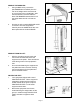
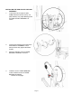
REMOVE THE SHROUDS: 1. Using a 4MM hex key remove the (M6,30MM,Button Head Bolt) from the rear of the weight stack. Save this bolt as you will need it to re-install later. After the bolt has been removed rotate the black TOP BUMPER towards the front of the weight stack then lift it off and set aside. 2. Grip the top of the outside SHROUD and lift to remove it from the weight stack. Carefully store the SHROUD for later use. Now repeat with the inside SHROUD. REMOVE FROM PALLET: 1.
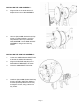
INSTALLING THE WELDED CROSS SUPPORT: 1. Locate the CROSS SUPPORT and align the holes as shown. INSTALLING THE WELDED CROSS SUPPORT, FRONT SCREWS: 1. Use three ( M8, 25MM, Button Head Bolt), three (M8, Nyloc Nut), and six (M8,Washers) to install and tighten the WELDED CROSS SUPPORT, as shown. 2. Use one (M8, 105MM Button Head Bolt), one (M8, Nyloc Jam Nut), and one (M8, Washer) to install and tighten the PULLEY assembly as shown, using a 5mm hex key socket.
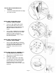
INSTALLING THE ROM ADJUST AND CAM ASSEMBLY: 1. Locate (from left to right) one (M8, 20MM, Socket Head Cup screw), one (M8, Washer), two (Taper Bearings) and the ROM ADJUST ASSEMBLY as shown. 2. Insert a taper bearing to the shaft of the ROM ADJUST ASSEMBLY until it bottoms all the way against the ROM PLATE. 3. Place the assembly into the TAPER BEARING HOUSING, as shown. 4. Install the second TAPER BEARING onto the shaft and into the TAPER BEARING HOUSING. . . .continue to next page. . .
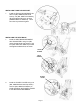
INSTALLING THE CAM ASSEMBLY : 5. Align the flat on the shaft with the DShaped slot on the CAM ASSEMBLY. 6. Use one (M8, 20MM, Socket Head Cap screw), one (M8, Washer), one (End Cap Without a Groove) to install the CAM ASSEMBLY to the ROM ADJUST ASSEMBLY using a 6mm hex key socket. INSTALLING THE SHIN PAD ASSEMBLY: 1. Locate one 20MM diameter SHAFT with a flat and the SHIN PAD assembly. 2. Align the SHIN PAD assembly to the ROM ADJUST BRACKET, as shown. 3. Insert the 20MM SHAFT with a flat. 4.
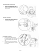
INSTALLING THIGH PAD SUPPORT: 1. Install the THIGH PAD SUPPORT along with one (M8, 20MM Socket Head Screw), one (M8, 1MM Thick Washer), (End Cap Without Groove), and two (25MM ID Machine Washers). Use a 6mm hex key socket to tighten. INSTALLING THE SEAT BACK: 1. Install the SEAT BACK WELDMENT with UPHOLSTERY using four (M8, 16mm Socket Head Cap Screws), and four (M8, 1MM Thick Washer) to install and tighten the Back Rest, as shown. FRONT SCREWS BACK SCREWS PLASTIC COVER 2.
INSTALLING THE SEAT BOTTOM: 1. Using four (M8,25MM,Button Head Bolts) and four (M8,washers) install and tighten the SEAT BOTTOM using a 5mm hex key socket. INSTALL THE CABLE: 1. Locate the loose cable end and loop around the pulley as shown making sure not to fray the stranded wire. ATTACHING THE CABLE: 1. Pull and insert the CABLE END into the CABLE MOUNT of the CAM until the end of the CABLE is visible in the sight hole. 2. Secure with the four sets screws (M8) included, using a 4MM hex key.
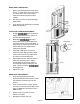
GUIDE ROD LUBRICATION: 1. Apply a general purpose lubricant (such as 3-in-1 oil) that does not contain Teflon to a cotton cloth, then run the cotton cloth up and down the guide rods as needed. 2. Also apply oil to the incremental weight guide tracks. 3. Verify that the Top Plate and Incremental Plate slide smoothly. Incremental Guide Track TOP PLATE & CABLE ADJUSTMENT: 1. Engage pin at maximum weight and actuate arm 3 to 4 times to fully seat the weight stacks. 2.
INCREMENTAL WEIGHT ADJUSTMENT: 1. Check to make sure the gap between the TOP PLATE pin and the 20mm hole of the INCREMENTAL WEIGHT plate is 3mm or less when engage. 2. If gap is greater than 3mm, loosen but do not remove the two BUTTON HEAD SCREWS (M6) using a 4MM hex key. 3. Slide the bracket up or down to create a 3mm gap. 4. Re-tighten the two BUTTON HEAD SCREWS. INCREMENTAL WEIGHT PLATE GAP SCREWS INSTALLING THE SHROUDS: 1. Insert the SHROUDS from the top sliding downward.
INSTALLING THE TOP BUMPER: 1. After both shrouds have been installed install the black TOP BUMPER by first inserting the two tabs (1) found on the large end of the TOP BUMPER into the equipment main frame. Now rotate (2) the TOP BUMPER down until it is sitting flush on top of the weight frame. Install the (M6,30MM,Button Head Bolt) (3) through the weight frame into the TOP BUMPER as shown and tighten to 1.0 N-m max.
Page 13
STAR TRAC 14410 Myford Road Irvine, California 92606 Telephone: (800) 228-6635, (714) 669-1660 Fax: (714) 508-3303 www.startrac.com Part No. 620-7929, Rev B.