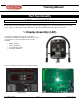
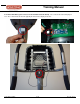
Training Manual Part Functionality E-ST (Model 9-5090), LED Display In this section, we will review all the components that make up the stepper. To resolve issues that may occur on an E Series stepper, it is important to understand all the components and what function they play in the system. 1. Display Assembly (LED) The display assembly is like the brains of the unit. It controls and commands the stepper to take actions. It is the user interface to control the machine.
Training Manual Components that connect to the display electronic: STAR TRAC FITNESS 2 of 22 637-1376 Rev: A
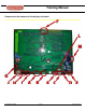
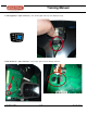
Training Manual A. Display Panel (J7 – 12 pin connector) –The main keypad that is used to enter commands. B. Center Console, Basic (J8 – 6 pin connector) –The small keypad that has the ‘Quick Start’ key. If the unit has any kind of entertainment, there will be extra keys for that.
Training Manual C. CSAFE Power (J10 – 6 pin connector) – The external CSAFE port. Note: This port is only used to supply power to external add on audio accessories. D. Polar Receiver (J11 – 3 pin connector) – The telemetry/wireless heart rate plugs in here (receives the signal sent out by a chest strap).
Training Manual E. Contact Heart Rate (6 pin connector on the standoff heart rate board) – The contact heart rate board plugs in here. The contact heart rate board is typically mounted on the display electronics.
Training Manual F. Fan Keypad (J1 – 8 pin connector) – The small keypad at the top of the display housing. G. Fan Power (J3 – 2 pin connector) – The fan gets power from the display electronic.
Training Manual H. Primary Port (J6 – 10 pin connector) – The primary port for uploading software into the display. I. Secondary Port (J5 – 10 pin connector) – The secondary port for uploading software into the display.
Training Manual J. Display Cable (J4 – 12 pin connector) – This is the main cable that connects the display to the LCB. The display cable is like the nerves of the stepper. Information and power are sent up to the display and back down to the LCB to control the unit. The display cable passes: • • • Power to the display Commands for resistance level Signal for RPM The data cable is polarized so it cannot be plugged in incorrectly.
Training Manual K. TV Interface (J9 – 7 pin connector) – NEVER use this port. L. HR Board Ground Cable – connects to the display frame.
Training Manual M. CCB (J14 – 7 pin connector) Used for PVS and on “Made for iPod” kits only.
Training Manual 2.
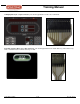
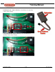
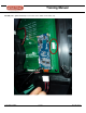
Training Manual The LCB is the heart of the stepper. The LCB brings the power from brake and conditions it for distribution to the display electronic.
Training Manual Connections and Components that plug into the LCB (PN: 711-3162) A. RPM Sensor Connector (J1 – 4 pin connector) – This is where the LCB receives the signal from the RPM Sensor.
Training Manual B. Alternator Cable Connector (J2 – 10 pin connector) – Brings in the power from the alternator and controls the resistance on the pedals. The battery cables are included with this connector to supply power for pause. . C. Resistor Connector (‘R1_A’ and ‘R1_B’) – These connect to the two resistors. ‘R1_A’ connects to bottom connector and ‘R1_B’ connects to the top connector on the resistors.
Training Manual D. CSAFE Data Connector (J3 – 8 pin connector) – This is where the external CSAFE cable plugs in to the LCB for data transfer. E. Display Cable Connector (P1 – 12 pin connector) – Information and power are sent up to the display and back down to the LCB to control the unit.
Training Manual F. Software Uploading Connector (JP1 – 10 pin connector) – This is used to load software into the LCB.
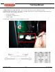
Training Manual 3. Other Electrical Components A. Power/Line Filter – Conditions the input power (when using the external power supply).
Training Manual B. External Power/CSAFE/Coax Cable Connector a. External Power Supply Port – Is needed when the unit has a PVS or embedded touch screen installed. b. CSAFE Port – This is where the RJ45 cable needs to be plugged in to make external equipment (like Fitlinxx) communicate with the unit. Note: The CSAFE port on the outside of the display only delivers 12 volts. c. Coax Cable Connector – This is where the coaxial cable connects to deliver TV signal to the PVS or an embedded touch screen.
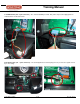
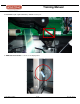
Training Manual 4. Mechanical/Drive Components A. Pedal Chain and Chain Springs a. The pedal chain is attached to the pedal linkage and drives the main shaft to create movement. b. The chain springs supply constant tension on the pedal chains and returns the pedals back to their original position (at the top).
Training Manual B. Sprocket/Clutch – This is where the chain goes around during pedal movement. During the down stroke the clutch (one way bearing) closes to drive the main shaft and during the up stroke the clutch opens up.
Training Manual C. Transmission Chain – Connects the pedal drive to the main drive.
Training Manual D. Alternator and Drive Belt a. Alternator Belt – Connects the alternator to the main drive. b. Drive Belt – Connects the lower pulley to the main pulley.