Section 1: Introduction Welcome to the world of STAR TRAC. In your hands is the STAR TRAC TR 4500 Service Manual. This manual is designed to be easy to use, providing detailed instructions on how to service and maintain the TR 4500. We highly recommend that you read all the applicable sections of the service manual prior to serving the treadmill. The information on the following pages will enable you to begin easily, quickly, and safely. Contents 1.1 How to use the Service Manual 1.
How To Use This Manual • This Service Manual has been written to assist and instruct the repair technician on key components for quick and efficient diagnosis of service problems. • To assist in finding the applicable sections in the Service Manual. Each Section has a table of contents to help locate specific symptoms and topics. Titles and major headings are located at the top of every page. • This manual is to be used strictly as a Maintenance manual for service and repair, not as an owner’s manual.
Precautions 1. Always make sure that the treadmill is turned off and unplugged before starting any work, unless otherwise noted, or when necessary for voltage testing. 2. Read each section through for NOTES before starting any work. 3. To pull apart electrical connectors, pull on the connector itself, not the wires. 4. When replacing fuses, be sure the new fuses is the correct amperage rating. Do Not exceed the fuse amp rating. If necessary use a fuse of lower rating until the proper fuse may be attained.
Product Support Asistance PRODUCT SUPPORT DEPARTMENT STAR TRAC Product Support Department sets the industry standard in Customer Service and Technical Assistance World Wide. Providing superior product support and customer service is at the very heart of STAR TRAC’s business philosophy. This commitment to service has been a major contributor to STAR TRAC’s success and growth in the worldwide fitness equipment industry.
Tools and Equipment Equipment Function Philips Head Screwdriver #2 Shroud Motor Control Board Assembly Side Bed Cover and End Caps Auto-Transformer Small Slotted Screwdriver 3/32” Motor Control Potentiometers (MAX SPD) & (IRCOMP) Bungee Cord 28” Suspend Motor Shroud on Display Rail 5/32” Hex Allen key Handrail assembly 5/64” Hex Allen key Display Board set screws 1/8” Hex Allen key Display Assembly 1/4” Hex Allen key Running Belt Head Roller Tail Roller 5/16” Wrench or Nut Driver Drive Moto
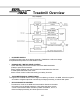
Treadmill Overview • DC POWER SUPPLY The MCB provides power to the display assembly. Establishes a reference voltage and potentiameter position from the elevation motor • RUNNING BELT MOTOR DRIVE CONTROL Takes Alternating Current and converts it to Pulse Width Modulation (PWM) to power the Drive Motor. Motor voltage feedback and control-speed-commands determine the level of PWM power delivered to the motor. Motor Control circuits include fault sensing and safety functions.
Section 2: Preventive Maintenance Schedules Performing regular preventive maintenance on all Star Trac treadmills is strongly recommended. Without preventive maintenance, normal wear and tear may cause cumulative effects, such as misalignment and early replacement of parts. This may result in downtime. For this reason, we highly recommend following the manufacturer’s maintenance schedules. Contents: 2.1 Preventative Maintenace Chart 2.2 Waxing Procedure 2.
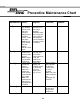
Preventive Maintenance Chart Maintenance Clean Daily Weekly Monthly Using a liquid non-abrasive cleaner, wipe down the following: display board handrails, shroud, heart rate grips. Note: Do not spray directly onto the display board or heart grips. Elevate the treadmill and vacuum under the unit. Note: Unplug the unit when vacuuming. Lift the motor shroud and vacuum around the motor and electronics. Clean and lubricate the elevtion screws. Note: This must be done with the unit unplugged and turned off.
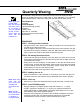
Quarterly Waxing The treadmill is designed with an automatic prompt, which will display RE WAX across the display screen every 2,000 miles or 3,000 kilometers. The procedure below explains step-by- step how to apply wax and clear the RE WAX prompt. Note: Apply wax powder while belt and deck are still warm (from 5 to 15 minutes of use) for optimum benefit. The following steps are done with the treadmill off.
Section 3: Diagnostics The STAR TRAC 4500 Treadmill series contains diagnostic and customizing modes. In these modes you are able to check accumulated data about the past usage of the treadmill, test its motor and display controls, and investigate display code messages. For these reasons, your treadmill is equipped with a ; • • • • • Manager Mode (customize) Maintenance Mode (diagnostics) Motor Test Mode (diagnostics) Display Test Mode (diagnostics) Heart Rate Test Mode (diagnostics) Contents: 3.
Manager Mode After having used you Star Trac 4500 treadmill for several workouts, you may wish to specially customize your treadmill by changing some of its settings. To engage Manager Mode: 1. Press and hold the “ 0 ”, “ 1 ” & “ START ” keys together. While holding the “ 0 ” & “ START ” keys down, release the “ 1 ” key only. 2. The display will beep and display Manager Mode momentarily, then UNITS will be displayed.
Manager Mode The following parameters may be changed using the previous keys: Parameters Lowest Value --UNITS Highest Value --- Option 1 Option 2 English Metric Default Value English Meaning English= units of lbs., miles, hours, minutes Metric= units of kg., km, hours, minutes. MN SPD 0.1 2.5 English=0.5 Metric=1.0 0.5 Minimum speed in MPH or KM/HR MX SPD 5.0 20.0 English=10.0 Metric=20.0 10.
Maintenance Mode Maintenance Mode includes all of the items of Manager Mode, plus additional data that is automatically saved to properly troubleshoot in case of a problem. To engage Maintenance Mode: 1. Press and hold the “ 0 ”, “ 2 ” & “ START ” keys together. While holding the “ 0 ” & “ START ” keys down, release the “ 2 ” key only. 2. The display will beep and display MAINTENANCE momentarily, then UNITS will be displayed.
Maintenance Mode The following parameters may be changed using the previous keys: Parameters Lowest Value --UNITS Highest Value --- Option 1 Option 2 English Metric Default Value English Meaning English= units of lbs., miles, hours, minutes Metric= units of kg., km, hours, minutes. MN SPD 0.1 2.5 English=0.5 Metric=1.0 0.5 Minimum speed in MPH or KM/HR MX SPD 5.0 20.0 English=10.0 Metric=20.0 10.
Maintenance Mode Parameters Lowest Value --HRT CON Highest Value --- Option 1 Option 2 ON OFF Default Value OFF Meaning OFF= Heart Control disable ON= Heart Control enabled CNT DN= Manual countdown heart rate POLAR, CONTACT or BOTH (Polar & Contact) HRT --- --- CNT DN POLAR CONTACT BOTH CNT DN POLAR CONTACT BOTH CNT DN 10 REV 22.0 74.0 30.7 = For 110v units. 35.8 = For 220v units 29.1 Inches of running belt travel for 10 flywheel revolutions, measured in inches. 1.8” pulley:30.
Maintenance Mode Parameters Lowest Value 0 KEY DN Highest Value 255 Option 1 Option 2 --- --- Default Value 0 NO RPM 0 255 --- --- 0 SP CNG 0 255 --- --- 0 EL STL 0 255 --- --- 0 EL RNG 0 255 --- --- 0 EL LOST 0 255 --- --- 0 ELZERO 0 255 --- --- 240 EL MAX 0 255 --- --- 57 LSTERR 0 25 --- --- 0 LSTELV 0 255 --- --- 0 LSTPOT 0 255 --- --- 0 3.6 Meaning Number of times the Stop Switch was down or disconnected on power-up since last reset.
Maintenance Mode Parameters Lowest Value 0 LSTRES Highest Value 2 Option 1 Option 2 --- --- Default Value 0 LSTSSP 0 255 --- --- 0 LSTPWM 0 255 --- --- 0 LSTMSP 0 255 --- --- 0 LST TM 0 65355 --- --- 0 LSTDCK 0 65355 --- --- 0 LSTBLT 0 65355 --- --- --- 3.7 Meaning Displays 1 = Unit was resetting to 0%. 0 = Unit finished resetting to 0% prior to the display code. Displays the speed prior to the display code. Displays the PWM number prior to the display code.
Motor Test Mode Motor Test Mode allows the treadmill to calibrate both elevation and running belt speed. Verifies RPM Sensor feedback, Drive Motor and MCB response, and verifies Elevation Motor range (count). Also burns in the motor, by way of the controls and displays of the treadmill. ***Caution*** : Do not stand on the running belt while performing these test. Engage Test Mode: 1. Press and hold the “ 0 ”, “ 1 ” & “ START ” keys together (or the “0” , “2” ).
Calibration ***Caution*** : Do not stand on the running belt while performing these test. Automatic Speed Calibration: In this mode minimum and maximum speed is automatically calibrated. Calibration lasts less than 3 minutes; belt will be in motion during this test. Auto-calibration should be done every time MN, MX SPD & UNITS parameters have been changed in either SETTINGS or CONFIGURE Mode.
Display Test Mode Display Test Mode allows you to test the light-emitting diodes (LEDs), 15-segment displays, and the watchdog timer of the Display Control Panel by way of its own controls and displays. It also allows EPROM version to be displayed. To enter Display Test Mode: ***Caution*** : Do not stand on the running belt while performing these test. 1. Press and hold the “ 0 ”, “ 1 ” & “ START ” keys together (or the “0” , “2” ).
Heart Rate Test Heart Rate Test Mode tests the heart rate calculation and display capability of the treadmill if it is equipped with contact rings or Polar wireless heart rate chest strap reception capability. To enter Heart Rate Test Mode: 1. Press and hold the “ 0 ”, “ 1 ” & “ START ” keys together (or the “0” , “2” ). While holding the “ 0 ” & “ START ” keys down, release the “ 1 ” (or 2) key. 2. The display will beep and display MANAGER (or MAINTENANCE) momentarily, then UNITS will be displayed. 3.
Section 4: Troubleshooting Should the STAR TRAC 4500 Treadmill experience a problem or a display code appear, the following procedures will help determine the precise reason for the problem. Included are flow charts breaking down each individual display code with problem statements and solutions. Contents 4.1 110v MCB Layout 4.24 Running Deck Symptoms 4.3 220v MCB Layout 4.26 Isolating Noise 4.5 Calibration Symptoms 4.27 Leveling 4.7 Manual Calibration 4.28 Static Symptoms 4.
110v MCB LED Layout The Following LEDs will help diagnose if the MCB has failed or causing intermittent problems. ** CAUTION ** Several of the following troubleshooting require dealing with live voltage. Have the treadmill turned off and unplugged when checking wire connections. NOTE: The display console may still power up with the AC LED off. AC LED - Indicates that AC power has been applied to the MCB.
110v MCB LED Layout NOTE: Engage Motor Test Mode and manually push on the running belt to verify RPM feedback. MOTOR LED - Indicates the presence of acceptable voltage to the motor. If this LED is not lit one of the following conditions exists: 1. Verify AC voltage is being applied. 2. Verify that MTR1/MTR2 wires are connected to the MCB. (This should be done with the treadmill unplugged and turned off) After the above have been verified and the MOTOR LED is still ‘OFF”, the MCB should be replaced.
220v MCB LED Layout The Following LEDs will help diagnose if the MCB has failed or causing intermittent problems. ** CAUTION ** AC PWR - Indicates that AC power has been applied to the MCB. It does Several of the follownot give indication of voltage level, if this LED is not lit and the ing troubleshooting treadmill does not power up, verify the following: steps require dealing 1. The treadmill is plugged into a wall outlet. with live voltage. 2. The ON/OFF switch is turned to the on position.
220v MCB LED Layout NOTE: Engage Motor Test Mode and manually push on the running belt to verify RPM feedback. RPM SENSOR - Indicates input signal from the RPM Sensor to the MCB. If this LED is not flashing during operation, verify the following 1. RPM sensor disconnected from connector J3 at the MCB. 2. RPM sesnor gap misaligned. 3. RPM sensor faulty After the above have been verified and the RPM LED is still “OFF”, the MCB should be replaced.
Calibration Troubleshooting The following steps help troubleshoot in case Auto-Calibration procedures fail to give the correct reading or response. Symptom: Diagram #1 Auto-Calibration fluctuates. 1. Verify line voltage for sufficient voltage supply. • If wall voltage is less than 10% than what is required, this will cause speed fluctuation. 2. Verify unit is on a dedicated circuit breaker. • Treadmills sharing the same circuit line will cause intermittent problems and variation in speed. 3.
Calibration Troubleshooting Diagram #1 Symptom: Will not Calibrate to MAX speed. 1. Verify line voltage for sufficient voltage supply. • If wall voltage is less than 10% than what is required, this will cause speed fluctuation. 2. Verify unit is on a dedicated circuit breaker. • Treadmills sharing the same circuit line will cause intermittent problems and variation in speed. 3. Verify the following parameters are set correctly in the Configuration Mode.
Manual Calibration The following procedure allows the treadmill to manually calibrate Minimum and Maximum speeds, only in the case Auto-Calibration is not functioning correctly. Symptom: Will not calibrate to MN or MX speed, in the Auto-Calibration Mode. **CAUTION** Do not stand on the running belt while performing these steps. 1. Engage TEST MODE. Press and hold the “ 0 ”, “ 1 ” & “ START ” keys together (or the “0” , “2” ). While holding the “ 0 ” & “ START ” keys down, release the “ 1 ” (or 2) key.
No Display Power The following steps help troubleshoot in case the display board fails to power up, during or before regular operation. 110v UNIT Diagram A Diagram B 1. Lift and suspend the motor shroud. **CAUTION** The following steps are performed with the treadmill “ON”. 2. Verify if LED AC is lit. AC LED indicates that AC power is being applied to the MCB, does not indicate voltage level. If this LED is lit go to step 3.
No Display Power The following steps help troubleshoot in case the display board fails to power up, during or before regular operation. 220v UNIT Diagram A Diagram B 1. Lift and suspend the motor shroud. **CAUTION** The following steps are performed with with treadmill “ON”. 2. Verify if LED AC is lit. AC LED indicates that AC power is being applied to the MCB, does not indicate voltage level. If this LED is lit go to step 3.
Elevation Motor The following procedure explains the elevation system Thermal Protection and limitations. Symptom: NOTE: Activation of the thermal protection breaker does not cause damage to the elevation actuator or other treadmill components. Elevation system shuts-off when used consistently. 1. The Star Trac Model 4500 elevation system actuator is protected from overheating by a thermal protection circuit.
Elevation Motor The following procedure verifies elevation motor potentiometer response. ** CAUTION ** Do not stand on the running belt while performing these steps. NOTE: Several of the following steps require dealing with “live” voltage. Have the treadmill turned off and unplugged when checking wire connections. NOTE: The potentiometer values can be read in Motor Test Mode, 240 = 0%, 57 = 15% for 110v units or 80= 15% for 220v units.
Elevation Troubleshooting 220v treadmill Incline Range Adjustment for Free-wheeling symptom. Symptom: ** CAUTION ** Do not stand on the running belt while performing these steps. Treadmill free-wheels at high elevation, causing the running belt to slowly accelerates beyond the selected speed. 1. This symptom may be easily fixed by changing certain values in the Configure Mode.
Speed Troubleshooting Symptom: Note: This symptom may be easily fixed by verifying certain values in the Configure Mode. Treadmill appears/feels faster/slower than other STAR TRAC treadmills. 1. Engage Maintenance Mode by holding down the “0”, “2” and “Start” keys at the same time, and then release the “1” key only. Display will read MAINTENANCE momentarily then display UNITS. 2. Using the elevation “ ↑ “ key to go through the parameteres, verify the following parameterts have the correct values.
Speed Troubleshooting Symptom: Treadmill will not reach maximum speed. Note: This symptom may be easily fixed by verifying certain values in the Configure Mode. Note: For each value changed the “ENTER” key must be pressed to be saved. Note: All 110v units are designed to reach a maximum speed of 10.0 MPH. 220v units set in metric will reach a maximum 20.0 KM/PH. Note: Wall voltage is very critical when dealing with maximum speed.
Speed Troubleshooting Symptom: Treadmill jerks or hesitates during operation. ** CAUTION ** Running belt will be moving at high speed during Step 1 & 3. ** CAUTION ** When checking motor brushes have the treadmill turned off and unplugged. Note: Brushes should show a smooth pattern of wear, cracks or unusual wear will cause motor to jerk, replace if brushes if neded. 1. Verify the running belt / drive belt are not loose or slipping. • • Accelerate the running belt to 3.0 (5.0 kph).
Heart Rate Troubleshooting Before any troubleshooting is performed, verify that the heart rate grips are being used and maintained properly. ** CAUTION ** Do not stand on the running belt while performing these steps. Symptom: Intermittent or erratic heart rate reading. 1. User failing to grip all four rings completely with both left and right hands 2. An excessively tight grip on the rings can cause erratic readings.
Heart Rate Troubleshooting Symptom: Diagram 1 No Heart Rate reading. 1. Engage HEART RATE TEST. Turn the • • 2. • • power switch “on” while pressing key “5” simultaneously on the display. All the display LEDs will light up when engaged. Press the HEART key once, EPROM version will be displayed. HEART key twice, displays Heart/ Seeking HR. Grip heart rate handles, The negative (-) symbol will begin to flash indicating heart rate system is being registered.
Heart Rate Troubleshooting 5. Connect Heart Rate Board straight to the display input. • By-pass the Combiner Board, insert the heart rate wires straight to the display. See Diagram #3 & 3a. After connection has been repeat step 1. REPLACE: Combiner Board if Heart Rate registers. If no Heart Rate is registered go to step 6. NOTE: Step 5 can only be performed if the software includes both Polar and Contact. Diagram 4 Diagram 5 6. Check continuity/resistance between Heart Rate grip rings and input wires.
Polar Heart Troubleshooting If the display is having difficulty picking up polar heart rate readings, verify proper usage. Symptom: ** CAUTION ** Do not stand on the running belt while performing these step. Intermittent or erratic polar heart reading. NOTE: Secure the chest strap transmitter as high under the pectoral muscle (breast) as is comfortable and allow normal breathing. properly positioned and wet. See below diagrams. 1. The maximum distance for polar heart rate to receive a signal is 3 feet.
Display Cable The following symptoms indicates a faulty or pinched display cable. Symptom: No display power related. **CAUTION** 1. No display power, treadmill elevation bottoms out during start-up. Do not stand on 2. No display power, MCB LED +11 remains lit on 110v units. MCB LED Display the running belt remains lit on 220v units. while performing these steps. Intermittent or no elevation. 1. In Test Mode only up direction works, MCB LED “UP” remains lit. NOTE: Alter2.
Drive Motor The following symptoms indicates a faulty drive motor. Symptom: Tripping the ON/OFF switch breaker. **CAUTION** Do not stand on the running belt while performing these steps. NOTE: If the ON/OFF swith trips only with a load, running belt may be worned. 1. Disconnect the drive motor belt. 2. Run the drive motor for ten minutes at a high speed (6 MPH/ 10 KPH).
Head / Tail Roller You may need to replace the head or tail roller if the following symptoms are observed. Symptom: Thumping, knocking noise as the running belt goes over the roller. Verify the following: • Delron end caps are loosening. • Bearings are grinding or knocking. • Lagging (coating) is loose. • Thumping sounds (may also indicate a possible wax build up). The running deck surface is coated with a special wax.
Drive Belt Troubleshooting The drive belt tension may require tightening if a slipping problem occurs on the drive pulley. Symptom: Running belt slips when running or walking. 1. Loosen the four motor mount kep nuts and washer using a 5/16 “ wrench. 2. Adjust the drive belt tension by turning the motor mount adjustment (socket head cap) screw. See diagram below. Tension should be no more than 90 lbs. • If too tight, turn the belt tension screw counter-clockwise.
Running Belt Troubleshooting Note: For optimal To prevent belt problems from occurring, verify the running belt is properly performance during the adjusted and working smoothly by performing the following steps: lifetime of the treadmill, running belt adjustments may become necessary. All adjustments are performed by adjusting the tail roller Allen screws with a 1/4” Allen wrench. 1. Feel the underside center of the running belt, for glaze.
Running Belt Tracking Note: The running belt If the running belt is not centered on the tailroller and is either to far left or may mis-track due to right, adjust tracking using the following steps:: the style of the walker or runner. 1. Turn treadmill on. Increase speed to 3.0 mph (5.0 kph). Note: The running belt will track to the side less tensioned. 2. Adjust tracking by adjusting the tailroller Allen screws located at the back sides of the tail roller with a 1/4” Allen wrench in 1/4 turn increments.
Running Belt Tension Note: Prior to making The running belt tension may need to be adjusted over time to keep the any adjustments to the the belt from slipping with each jogging step or at high speeds. Use the running belt tension, following procedure for testing belt tension. verify the drive motor belt is properly tensioned. 1. Accelerate the running belt to 3.0 mph (5.0 kph). 2. Stand on the side of the treadmill.
Running Deck The following procedure will help determine and properly adjust the deck bumpers. Symptom: Running deck squeaks when running. 1. When properly located, the side bumpers (two on each side) bear against the delrin rods in the frame rails. The rear bumpers bear against the steel posts at the end of the frame rails. If the bumpers are not located so they bear against the rods as described, the running deck may shift to one side or the other during use.
Running Deck Symptom: Running deck squeaks when running (continued). Correcting the problem: 1. Position the deck with the rear bumpers properly aligned with the steel posts. With a pencil, make a mark on the deck adjacent to each of the four delrin rods( as seen from the top of the side rails). 2. Reach under the running deck, shift the deck as far as possible to tone side.
Isolating Noise Sounds travel throughout the treadmill making it difficult to isolate the cause of a sound. The following procedure will help determine where a noise may be coming from. NOTE: Verify that Isolate the noise. the treadmill is level 1. If the noise seems to be coming from two different parts (drive motor or roller before isolating any etc.), isolate the noise by disconnecting the drive belt. Then run the drive motor specific component by itself.
Leveling To ensure proper tracking of the running belt, treadmill leveling should be verified. Symptoms: NOTE: If a leveling foot does not make contact with the floor or if it lifts upwards as weight is applied to one corner of the deck, this will cause the running belt to mis-track. • Running belt travels to one side. • Treadmill vibrates. Leveling feet must be adjusted to conform to the floor surface.
Vibration A treadmill vibrates during use if the floor or leveling feet are uneven or when assembly bolts are loose. Symptom: Unit vibrates while running. 1. Verify the treadmill is on an even, uncarpeted floor. NOTE: For complete leveling procedure, see the following page. • • If no, move the treadmill to an even floor. If floor is carpeted, place the treadmill on a rubber mat. 2. Verify that the Leveling feet are adjusted correctly. 3. Verify the following assemblies.
Static Shock The treadmill may cause a slight shock from the display panel or handrails, due to a faulty ground wire or a worn running belt and deck. **CAUTION** When checking motor brushes, always turn the treadmill off and unplug. Symptom: Slight shock from handrails or when using the display panel. 1. Check the line cord and plug prongs for signs of damage. • Verify no prongs are broken, loose or missing. 2.
Display Codes Chart ** CAUTION ** Do not stand on the running belt, while performing these steps. STAR TRAC recommends that you refer your questions about your STAR TRAC 4000 TREADMILL operation and suspected malfunctions to STAR TRAC’s PRODUCT SUPPORT DEPARTMENT. However, you may wish to investigate display codes that appear on the display. You may do so by reviewing the below chart or follow the step-by-step flowcharts for the corresponding display code.
Code: KEY DN Flowchart Note4 : Carefully peal off the affected keypad. Wipe the display surface with degreaser (Windex works well). Re-apply the keypad starting from one edge and using your fingers or a rag press the keypad in one direction to remove the air bubbles. Definition: "KEY STUCK" Possible Cause: Damaged or shorted key/keypad. Start Note 1: This code may occur when a user tried entering "Test Mode" or "Display Test Mode" using the wrong key. Look for any indentations on any of the keys.
Code: NO RPM Flowchart Definition: "RPM LOSS" Possible Cause: Damaged or misaligned RPM sensor. Start Note 1: Press and hold the "0", "1," & "START" keys down at the same time, then release the "1" key. The display will read: MAINTENANCE. Then press and release the 8 key. Or manually hold the 8 key and simultaneously turn the treadmill on by the on & off switch. Both methods will engage "Test mode". Engage "MAINTENANCE" mode. Verify RPM feedback in "Test Mode". See (note 1) Display reads: XXX 3 .
Code: NO RPM Flowchart 1A Note 5: RPM Sensor gap between the Halll Effect pickup adn teh flywheel should be no more than 1/8 inch. If not, adjust the RPM sensor to correct gap. 2A If no appearant damage is visable. Manually toggle the display cable for possible intermittent connection. Process Diagram #2 If the PWM LED does not flash or intermittently respond, replace the display cable. STOP Does display read RPM feedback ? YES NO Replace RMP Sensor Engage automatic speed calibration.
Code: NO RPM Flowchart 1B Check the following connections; drive motor to choke/filter to MCB. Re-engage Test Mode. Bring speed command 3 back up to 50. Does the running belt move ? YES Re-engage AutoCalibration. See (note 4) NO By-pass the choke/filter from the MCB and drive motor. Stop Does the running belt move ? YES Replace the choke/filter system. NO Replace the MCB Stop Stop 4.
Code: SP CNG Flowchart Definition: "SUDDEN SPEED CHANGE." Possible Cause: RPM pick-up misaligned. Start Note 1: Press and hold the "0", "1", & "START" keys down at the same time, then release the "1" key. The display will read: MAINTENANC, then press and release the "8" key. Or, manually hold the "8" key and simultaneously turn the treadmill on by the on & off switch. Both methods will engage "Test Mode". Note 2: Verify that the PWM LED is flashing, while the treadmill is on.
Code: SP CNG Flowchart 1A Note 5: Turn the treadmill off and unplug. Remove one brush at a time. Check for unusual wear, replace if needed. LED responds ? 1B Check motor brushes, for unusual wear. See (note 5) Diagram #3 YES NO Manually toggle the display cable for possible intermittent connection. If the PWM LED does not flash or intermittently respond when cable is toggled, replace the display cable. Stop Replace the M.C.B.
Code: SP CNG Flowchart 1C 1D Note 6: To engage automatic speed calibration, press the "HEART" in Test Mode. The display will read: CALI. Treadmill will then go into a self auto speed calibration. This will automatically calibrate MIN PWM, 1/2 MAX, and MAX PWM for min and max speed. This will take less than 3 minutes. Treadmill will be in motion, during this test. Engage automatic speed calibration. See (note 6) Check the following: 1. RPM connection to J3 connector. 2. Check alignement.
Code: SP CNG Flowchart Note 8: Engage "Maintenance Mode" Scroll up through the menu to the different error references by using the "UP" elevation key. Clear all error codes by pressing the "HEART" key. Diagram #5 Does display read RPM feedback ? NO YES Engage automatic speed calibration. Replace the RPM sensor or Hall Effect, depending on style. Then clear all error codes, see (note 8) Exit "Test Mode" by pressing the stop key. Re-engage "Engineering Mode" and clear all error codes.
Code: EL LOST Flowchart Definition: "ELEVATION LOST BEYOND 0% or 15% RANGE" Possible Cause: Out of range elevation count or elevation system malfunctioned. Start Note 1: Press and hold the "0", "2" & "START" Engage keys down at the same "TEST MODE" time, then release the "1" Verify elevation key. The display will read: MAINTENANCE. response in "Test Press and release the Mode". "8" key. See (note 1) Or manually hold the "8" key and simultaneously turn the treadmill on by the on & off switch.
Code: EL RNG Flowchart Definition: "ELEVATION RANGE Is incline greater than 240 ? BEYOND 0% or 15% RANGE" Possible Cause: Out of range elevation count or elevation system malfunctioned. Is incline less than 57 or 80 ? NO YES YES Note 1: Press and hold the "0", "2" & "START" keys down at the same time, then release the "1" key. The display will read: MAINTENANCE/. Press and release the "8" key. Or manually hold the "8" key and simultaneously turn the treadmill on by the on & off switch.
Code: EL RNG Flowchart 1A 1B Disconnect the elevation motor belt and manually bring down the elevation until display read 240. Bring the treadmill down to physical 0% 240, using the elevation down key. Re-connect the elevation belt. Elevation responds ? NO YES Re-ingage regular mode. Verify if elevation is operating correctly. If elevation is working see (note 4) If display code continues contact Unisen. Re-ingage regular mode. Verify if elevation is operating correctly.
Code: EL STL Flowchart Definition: "ELEVATION STALL BEYOND 0% or 15% RANGE" Possible Cause: Out of range elevation count or elevation system malfunctioned. Start Note 1: Press and hold the "0", "2" & "START" keys down at the same time, then release the "1" key. The display will read: MAINTENANCE. Press and release the "8" key. Or manually hold the "8" key and simultaneously turn the treadmill on by the on & off switch. Both methods will engage "Test Mode".
Code: EL STL Flowchart 1A Note 4: Diagram #2 Place your (red) meter probe into the black wire of pin 4, located at connector J5. Then place your (black) meter probe to AC1 on the M.C.B. Voltage should read +/-110v. or +/-220v depending on model. When pressing the elevation "DOWN" key, the voltage should drop down to 0v or 1v. This would indicate a good response from the M.C.B. Do the same for pin 5 (red wire), as shown in Diagram #4. Then press the elevation "UP" key. Voltage should drop down to 0v or 1v.
Section 5: Parts Replacement Should the STAR TRAC 4500 Treadmill experience a problem requiring replacement of a specific part, the following procedures will help and instruct in the replacement of major parts. Contents 5.1 – 5 Drive Motor Replacement 5.13 – 15 Auto-transformer Replacement 5.6 – 9 Elevation Motor Replacement 5.16 – 19 Heart Rate Grip Replacement 5.10 – 12 Side Bed Cover Replacement 5.
Drive Motor Replacement Tools: ** CAUTION ** Always turn the power switch to the off position. Unplug the treadmill power cord from the power outlet. • • • • • • • • • • Running Belt Drive Motor Philips-head screwdriver Bungee cord, approx. 24 inches Needle nose pliers 5/16-in socket and torque socket wrench to measure 110 in/lb. 1/8-in. Allen torque wrench to measure 75 in./lb. Plastic hammer Punch Straight edge, 24 inch Belt Tension Gauge, to 90 lbs.
Drive Motor Replacement Remove Motor 1. Loosen the 5/16-inch nut that locks the motor alignment screw, then unscrew the screw several turns. 2. Loosen the four 5/16-inch motor mount nuts so that the motor slides freely on the frame. See Diagram A below. 5.
Drive Motor Replacement 3. Using a 1/8-inch Allen wrench, loosen the two set screws in the motor pulley. 4. Slide the motor towards the rear of the treadmill l to give slack to the motor drive belt. 5. Slip the drive belt off the motor pulley, then remove the pulley and the locking key. 6. Remove the four motor mount nuts, then lift the motor out of the treadmill and set I aside. Mark it as the removed motor to avoid confusion with the replacement motor. This completes motor removal procedures.
Drive Motor Replacement Diagram B. Check and Adjust Belt Tension 1. Place a tension gauge onto the center of the belt and check tension. The gauge should indicate 90 inch-pounds. 2. If you have not tension gauge, press down on top of the belt, midway between pulleys, very hard with your thumb. The belt should deflect between 3/8 inch and ½ inch. 3. Screw the motor adjustment screw against the motor mount, moving the motor towards the front of the treadmill pulleys to equalize tension through the belt. 4.
Drive Motor Replacement 5. Recheck pulley alignment and belt tension. 6. When alignment and tension are correct, tighten all four motor mount nuts using a socket torque wrench set at 75 inch-pounds. 7. Lock the motor adjustment screw by tightening the locking nut against the frame. 8. Loosen the set screw at the motor pulley, then recheck alignment. 9. Slide the pulley on the shaft until alignment is restored. 10.
Elevation Motor Replacement Tools: ** CAUTION ** Always turn the power switch to the off position. Unplug the treadmill power cord from the power outlet. • • • • • • • • Replacement elevation motor Philips-head screwdriver Pliers Tap nuts, ½-inch (2) Allen wrench, 9/64 in. Socket wrench with 17-mm socket Shop hammer Large screwdriver or steel chisel Procedure: Lift motor shroud The drive motor is located below the plastic shroud at the front of the treadmill.
Elevation Motor Replacement Diagram A 4. Slide the idler pulley in its slot to loosen the elevation drive belt, then remove the belt from the idler pulley. 5. Using an Allen wrench, loosen the screws around the drive pulley, then remove the pulley from the elevation motor shaft. 6. At the Motor Control Board, disconnect the elevation motor cable from connector J5. 7. At the upper surface of the motor plate, remove the four screws that hold the elevation motor to the motor plate.
Elevation Motor Replacement Replacement the Elevation Motor 1. Position the elevation motor in its mount. Be sure to hold the motor’s electrical cable closely against the motor to prevent its being pinched between the motor and the treadmill frame. 2. Replace and tighten the four screws that hold the elevation motor to the motor plate. Use a 9/64-inch Allen wrench. 3. Connect the motor cable connector to the connector J5 on the Motor Control Board. 4.
Elevation Motor Replacement 6. Tighten Allen screws in the drive pulley, taking care to preserve the alignment achieved in the preceding step. 7. Place the drive belt over the idler pulley. 8. Slide the idler pulley tightly against the belt, then finger tighten the mounting screw on the idler pulley shaft. 9. Manipulate the drive belt so tat tit is flush with the inside surface of all pulley flnages and the right-hand drive screw bearing. 10. Tighten the idler pulley mounting nut ¼ to ½ turn. 11.
Side Bed Cover Replacement Tools: ** CAUTION ** Always turn the power switch to the off position. Unplug the treadmill power cord from the power outlet. • • • • • • • Side bed cover Philips-head screwdriver Slot-head screwdriver 1/8-in Allen wrench 5/8-in socket and socket wrench with ratchet Plastic-head hammer Wooden block Procedure: Removing the Side Bed Cover. 1. Remove the 5/8-in. hex-head screw at the bottom of the frame and inline with the bottom end of the vertical section of the handrail.
Side Bed Cover Replacement 4. Starting at the raised corner of the flange, lift upwards and outwards to free its outer edge from the frame along its length. 5. Lifting the outer edge of the cover, push the cover towards the center of the treadmill to clear the cover’s inner flange from the frame and remove from the treadmill. Installing Replacement Side Bed Cover To replace the cover, proceed as follows: 1.
Side Bed Cover Replacement 4. At the front end, pull the outer flange over the frame, then use your hand or a soft mallet to “pop” the outer flange over the frame along its full length. The rear end of the cover should butt against the end cap. See Diagram C. Diagram C 5. If the rear end of the cover does not meet the end cap, set a short section of wooden board against the front end of the cover, then tap the board with a plastic hammer to slide the cover flush against the end cap. 6.
Autotransformer Replacement The autotransformer may be tapped to accommodate line voltages from 195VAC to 250VAC. Following are procedures for replacing a failed autotransformer. Tools: • • • Replacement autotransformer Philips-head screwdriver Slot screwdriver Procedure: Lift motor shroud The drive motor is located below the plastic shroud at the front of the treadmill. To remove the shroud at access the motor, proceed as follows: 1.
Autotransformer Replacement Replace the Autotransformer 1. Position the replacement autotransformer over the four holes in the motor plate so that the connector lugs are towards the left-hand side of the treadmill. 2. Drop the four screws removed in the preceding step 5 into the mounting holes of the autotransformer. 3. Reaching under the treadmill, install related washers and nuts, and tighten the mounting screws. 4. Reconnect the autotransformer’s brown wire to terminal AC1 on the barrier strip. 5.
Autotransformer Replacment Reconnect the autotransformer’s black wire to terminal AC1 at the left-rear corner of the Motor Control Board. Connect the blue wire to the lug on the autotransformer. 1. Connect the red wire to the same lug from which it was removed in the previous step. If there is a question about the available line voltage, or if EL STL messages have been appearing on the display, check and follow the recommendations in Selecting the Voltage Tap. Replace the Shroud 1.
Heart Grip Replacement Tools: ** CAUTION ** Always turn the power switch to the off position. Unplug the treadmill power cord from the power outlet. • • • • Handgrip Kit 1/16 inch Allen wrench Light nylon cord Isopropyl alcohol Procedure: Remove the Display Panel 1. Using a 1/16-inch Allen wrench, remove the five screws from the rear of the display panel mount and carefully lay the panel down on the display rail. 2. Unplug the two handgrip cables from their connectors. See Diagram A. Diagram A 5.
Heart Grip Replacement 3. Lift the handgrip cables to separate the Velcro strips on the cable from the Velcro on the rear of the panel, then remove the two Velcro strips that hold the two cables together. 4. Cut and remove the cable ties from the handgrip cables. 5. Tie a 4-foot length of strong nylon cord to each cable, just below the connector. See Diagram B. Secure the free end of each cord so that it will not be pulled into the gooseneck.
Heart Grip Replacement Remove the Handgrips 1. Pull and twist the handgrips free of the rail tubing. If they will not slide off the tubing, use a knife or scissors to cut the rubber along its length, then slide the handgrips off the tubing. 2. Continue to pull each of the handgrip cables though the gooseneck and the display rail until they emerge with the nylon cord attached. 3. Remove the nylon cord from each cable and discard the handgrips. Replace the Handgrips 1.
Heart Grip Replacement Replace Display Panel 1. Position the display panel over the display panel mount, matching screw holes in the back of the panel with holes in the mount. 2. Using a 1/16-inch Allen wrench, replace and tighten each of the five screws removed in a previous step. Test Treadmill Operation After you have completed replacement of the handgrips, perform a complete system test. 5.
TR 4500 & 3900 Series Page: 1 Deck & Frame Assy Item No Part Number 1 2 3 4 5 6 7 8 9 10 11 12 13 14 15 16 17 18 19 20 21 22 23 24 25 26 27 28 29 30 31 020-4497 020-4500 020-4452 020-4480 020-4453 020-4481 050-1630 010-3061 140-3108 715-3196 020-4544 020-4584 020-4543 020-4583 140-3200 110-1823 020-4454 020-4627 110-3066 120-3002 110-0475 110-1790 110-1000 120-0460 110-1830 140-0492 050-1721 050-1716 140-3180 710-1031 710-1035 Description Shroud, Motor, black, 45/39/4000Sm Shroud, motor, grey, 45/39
TR 4500 & 3900 Series Page: 2 Elevation Assy Item No Part Number 1 2 3 4 5 6 7 8 9 10 11 12 13 260-0235 708-0151 715-0110 130-0250 110-1415 708-0645 020-6266 020-6268 130-1280 130-0050 800-0225 110-0477 120-0420 Description Motor, Elevation, 110vac Elevation Can Elevation Screw, drilled Pulley, Elevation, elev motor Axle Push Caps 1/2" Axle 1/2" Sleeve, Elevation Axle Spacer, Elevation (screw/wheel) Wheel, 3"x 1"x 1/2" bore Elevation Belt Elevation Idler Pulley, Assy Screw, 1/4-20 X 3/4" Shcs Washer
TR 4500 & 3900 Series Page: 3 Motor & Electrical Assy Item No Part Number 1 2 3 4 5 6 7 8 9 10 11 12 13 14 15 16 17 18 19 20 21 22 800-3016 715-3132 800-3259 800-3258 260-0220 260-0903 140-3111 800-3260 800-3245 800-3229 470-0190 470-0180 440-0095 020-0681 020-0493 110-0300 110-3026 110-1870 120-0480 110-1516 110-1510 140-0020 Description Mcb, 110v, 18/35/39/45/4000 Mcb, 220v, 18/35/39/45/4000 Filter Network, 110v Filter Network, 220v Motor, 110v, 2.5hp 3500rpm, mag Motor, 220v, 2.
TR 4500 & 3900 Series Page: 4 Running Belt Assy Item No Part Number 1 2 3 4 5 6 7 8 9 10 11 12 130-1630 708-0061 708-0132 130-0121 130-1629 130-7009 130-1628 110-1442 110-3056 110-0651 120-0490 120-0496 Qty Per Description Running Belt, (20"x128.5") Head Roller Tail Roller Drive Belt, (280J10) Drive Belt, (285J10) Pulley, drive motor, (10J180) 1.8"dia Pulley, drive motor, (10J210) 2.1" dia Key, motor/pulley, 3/16 X 1.
TR 4500 & 3900 Series Page: 5 4500 Handrail Assy Item No Part Number 1 2 3 4 5 6 7 8 9 10 11 12 13 14 15 16 17 18 19 20 21 22 23 24 25 715-3301 715-3302 715-3328 705-1663 711-1032 020-4600 110-0685 120-0480 120-0491 110-0506 140-3127 140-3133 709-0550 020-4592 020-4598 020-5037 020-5038 020-4582 020-4588 020-4581 020-4587 020-4589 020-4590 020-4580 020-4586 Qty Per Description Cable, Display, lower m/f, Tr4500 Cable, Display, upper m/m, Tr4500 Stop Switch, w/cable, 4500 (D04591 and up) Cable, Displ
TR 4500 & 3900 Series Page: 6 3900 Handrail Assy Item No Part Number 1 2 3 4 5 6 7 8 9 10 11 800-0126 110-0685 120-0480 120-0491 110-0506 710-0521 140-3127 020-4555 020-4535 020-4540 709-0550 Qty Per Description Cable, Display, 39/4000/18/35/900-1 Screw, 5/16-18 X 6" hex Washer, 5/16, cut Washer, 5/16 x 1.
TR 4500 & 3900 Series Page: 7 4500 Display Assy Item No Part Number Qty Per 1 2 3 4 5 6 7 8 9 10 11 12 13 14 15 16 17 18 19 91 92 93 94 715-3279 050-1722 050-1723 050-1724 020-4576 020-4577 140-2497 715-3131 711-1030 715-3280 800-3360 120-3012 110-3086 110-0250 110-0020 020-4579 Display Electronic, Pcb, Tr4500 Keypad Overlay, 4500/4200, left Keypad Overlay, 4500/4200, center Keypad Overlay, 4500/4200, right Lens, small, upper (1" x 6.
TR 4500 & 3900 Series Page: 8 3900 Display Assy Item No Part Number Qty Per 1 2 3 4 5 6 7 8 9 91 705-1635 050-1705 020-4496 020-4492 120-3004 110-0130 120-3002 Display Electronic, Pcb, 3900/3500 Keypad Overlay, 3900/3500 Lens, (3" x 8") Display Housing Standoff, 6-32 X 3/8 Screw, 6-32 X 1/4 Washer, #6 1 1 1 1 5 9 4 Y N N N N N N 705-1630 Display Assy Complete, Tr3500 1 Y Description Product Support Phn# 800-503-1221 Revision Date:09/18/00 Core Do Not Duplicate or Distribute