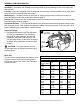
STAR MODEL SJ05 1/2 HP, SJ07 3/4 HP, SJ10 1 HP Deep Well 2 Pipe CONVERTIBLE JET PUMP ® Español p. 23 sw0900 a IL1612 ATTACH YOUR RECEIPT HERE Serial Number STOP Purchase Date Questions, problems, missing parts? Before returning to your retailer, call our customer service department at 1-800-742-5044, 7:30 a.m. - 5 p.m., EST, Monday - Friday. 1 95 North Oak Street • Kendallville, IN 46755 • © 2014 Star Water Systems. All rights reserved.
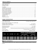
TABLE OF CONTENTS Product Specifications.......................................................................................................................2 Safety Information.............................................................................................................................2 Package Contents.............................................................................................................................4 Preparation....................................................
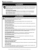
SAFETY INFORMATION DANGeR electrical shock hazard. Always disconnect power source before performing any work on or near the motor or its connected load. If the power disconnect point is out-of-sight, lock it in the open position and tag it to prevent unexpected application of power. Failure to do so could result in fatal electrical shock. electrical shock hazard. Do not handle the pump with wet hands or when standing in water as fatal electrical shock could occur.
SAFETY INFORMATION CAUTiON PRODUCT DAMAGE MAY RESULT This pump is not to be used for irrigation or water systems. PRODUCT DAMAGE MAY RESULT Protect the power cable from coming in contact with sharp objects. PRODUCT DAMAGE MAY RESULT Do not run pump dry. PRODUCT DAMAGE MAY RESULT Pump and plumbing must be full of water before startup. PRODUCT DAMAGE MAY RESULT Do not pump water which contains sand, mud, silt, or debris. INJURY MAY RESULT Be careful when touching the exterior of an operating motor.
PREPARATION Before beginning installation of product, make sure all parts are present. If any part is missing or damaged, do not attempt to assemble the product. Compare parts to package contents list and hardware contents list. Estimated Installation Time: 2 hours. Tools Required for Assembly (not included): pipe wrench, pliers, Phillips screwdriver, pipe clamp, 2-step PVC glue system (primer and sealer), thread tape Parts Required for Assembly (not included): 1-1/4 in. to 1 in. male PVC adapter, 1-1/4 in.
GENERAL PUMP INFORMATION Ventilation - Ventilation and drainage must be provided to prevent damage to the motor from heat and moisture. Freezing - Pump and all piping must be protected from freezing. If freezing weather is forecast, drain pump or remove completely from the system. Water Supply - The water source must be able to supply enough water to satisfy the capacity of pump and water needs. See performance chart on page 2.
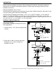
WELL TO PUMP CONNECTION (SUCTION PIPE) CAUTION: Dry-fit entire assembly to ensure proper fit before gluing or taping parts. CAUTION: Follow all proper gluing procedures as specified by the glue manufacturer. Always glue in a vertical direction whenever possible to prevent glue from dripping inside pipe or fittings CAUTION: Use pipe tape and pipe paste compound on all male threads. Tighten with wrench to a snug fit and add another 1/4 turn to ensure proper seal. Shallow Well Installations Only 1.
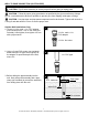
WELL TO PUMP CONNECTION (SUCTION PIPE) 4. Remove the pipe clamp and slide a well seal (not included) over the PVC pipe and onto the well casing. The PVC pipe should extend approximately 12 in. above the top of the well seal, depending on the height of the pump. 4 Approx. 12 in. NOTE: Do not let the assembly slide down into the well. Tighten the well seal until the rubber gaskets are tight against the well casing and the PVC pipe. Well Seal 5. Using a 2-step PVC system, attach a 1 in.
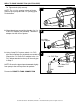
WELL TO PUMP CONNECTION (SUCTION PIPE) 7b. Tighten bolts (AA) securely. 7b NOTE: The 1-1/4 in. opening in back of ejector goes on top of pump and the 1 in. opening goes on the bottom. 8. Wrap thread tape around the threads of a 1 in. male PVC adapter (not included). Thread the adapter into the front of ejector. IL1538 8 1 in. Male PVC adapter 9. Using 2-step PVC system, attach 1 in. PVC pipe and couplings (not included) as needed to connect the 1 in. male PVC adapter to the 1 in.
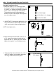
WELL TO PUMP CONNECTION (SUCTION PIPE) Deep Well Installations Only 1. Wrap both ends of a 1 in. close nipple with thread tape. Thread the close nipple into 1-1/4 in. male x 1 in. adapter and thread the adapter into a 1-1/4 in. foot valve (all not included). Thread the other end of close nipple into bottom of ejector. Hand tighten, then tighten 1 turn with a pipe wrench. 1 1 in. Close Nipple 1-1/4 in. Male x 1 in. Adapter 1-1/4 in. Foot Valve 2.
WELL TO PUMP CONNECTION (SUCTION PIPE) 5. T hread a 1 in. female PVC adapter (not included) onto the 1 in. x 5 in. nipple. Hand tighten, then tighten 1 turn with a pipe wrench. 5 1 in. female PVC adapter 1 in. x 5 in. nipple 6. Using a two step PVC system (not included) attach enough couplings and rigid PVC pipe (not included) to the adapters to equal the depth of the well minus 5 ft. IL1545 6 7.
WELL TO PUMP CONNECTION (SUCTION PIPE) 9. Cut the 1 in. pipe 2 in. shorter than the 1-1/4 in. pipe. Smooth rough edges. Using a two step PVC system, attach a 1 in. PVC elbow (not included) and a 1-1/4 in. PVC elbow (not included) to the pipes extending from the well seal. Both elbows should face the pump. 9 10. U sing a two step PVC system, attach enough rigid 1 in. and 1-1/4 in. PVC pipe and couplings to connect the pump to the 1 in. and 1-1/4 in. elbows. 10 2 in. 1-1/4 in. pipe 1-1/4 in.
PUMP TO TANK CONNECTION (DISCHARGE PIPE) 1. Wrap thread tape (not included) around threads of a 1 in. discharge tee (not included). Using a pipe wrench, thread the 1 in. discharge tee into the top of pump. 1 1 in. Discharge Tee NOTE: To improve performance and consistency, a flow control (not included) is recommended for deep well applications in place of a standard discharge tee. This will help regulate water pressure fluctuations and may prevent loss of prime. 2. Connect a 1 in. MPT x 1/4 in.
TANK TO HOUSE CONNECTION 1. Most pressure tanks will have a 1 in. inlet elbow on the bottom. Connect to this elbow with a 1 in. MPT x 1 in. slip (glue) adapter and short piece of pipe. 3 1 Adapter IL1365 Glue 2. Attach a 1 in. elbow (not included) to the pipe. Pipe 5 2 Elbow IL1366 Glue 3. Attach a 1 in. pipe (not included) to the elbow and a 1 in. x 3/4 in. reducer bushing (not included) to the pipe. 3 1 in. x 3/4 in. Reducer Bushing 1 in. Pipe Glue 4. Attach a 3/4 in.
TANK TO HOUSE CONNECTION 5. Attach the pipe from the pump to the tee installed in Step 4. Then, from the tee, install 3/4 in. pipe and optional shut off valve (not included) to connect tee to house plumbing. 5 Shut off valve Glue From Pump 6. I MPORTANT: Air pressure in the tank must be 2 PSI lower than the “cut-in” of the pressure switch. Pump has a 20/40 PSI pressure switch, so tank pressure must be set at 18 PSI.
PUMP ELECTRICAL CONNECTIONS Wiring the pressure switch 1. CAUTION: Make certain that the power source matches the pump requirements. This pump has a dual voltage motor and can run on 115 V or 230 V. This pump is pre-set at the factory to run on 230 V. Voltage swtich cover 1 NOTE: To change pump voltage, remove the square voltage switch cover at the top of pump and move the voltage switch as shown. 115 V Setting 2.
PUMP ELECTRICAL CONNECTIONS 5. Connect the green ground wire from the power supply to the remaining green ground screw in the pressure switch and re-attach the pressure switch cover. Ground Screws 5 Wire from power supply PUMP PRIMING AND STARTUP CAUTION: All pumps must be primed by filling the cavity with water before they are first operated. This may take several gallons of water, as the suction line will be filled in addition to the cavity of pump. 1.
PUMP PRIMING AND STARTUP 3. B e sure all pipes are filled when priming. Depending on the length of suction pipes, several gallons will be needed to fill the entire system. 3 4. Check to be sure water in the cavity of pump stays constant. If water level goes down, it could indicate a leak in the foot valve, check valve or suction pipe. 4 Water Level Check for Leaks 5. Once pump is filled, wrap the discharge tee plug and priming plug threads with thread tape and thread into pump.
PUMP PRIMING AND STARTUP IMPORTANT: If pump fails to prime within five minutes: Turn power off at the breaker box and check all pipe connections for leaks. All connections must be water and air tight in order for pump to operate. 7. Check suction pipe for any sagging. Support suction pipe in a straight line to the pump. 7 NOTE: Look for leaks or a milky color in the discharged water, which indicates an air leak. Re-prime if necessary, following steps 1 through 6 above. Reset breaker at the breaker box.
TROUBLESHOOTING Problem Little or no discharge. Possible Cause 1. P ump is not primed. 2. Suction lift too high or too long. 3. Hole or air leak in suction line. 4. Foot valve too small. 5. F oot valve or suction line not submerged deep enough in water. 6. Voltage switch incorrect. Pump will not deliver water or develop pressure. Pump vibrates and/or makes excessive noise. Pump will not start or run. 7. Casing gasket leaking. 1. Pump is not primed. 2. L eak in suction line. 3.
WARRANTY This product is warranted for one (1) year from the date of purchase or two (2) years from the date of manufacture, whichever occurs first. Subject to the conditions hereinafter set forth, the manufacturer will repair or replace to the original consumer any portion of the product which proves defective due to defective materials or workmanship. To obtain warranty service, contact the dealer from whom the product was purchased.
REPLACEMENT PARTS LIST For replacement parts, call our customer service department at 1-800-742-5044, 7:30 a.m. - 5 p.m., EST, Monday - Friday.