
Owner's manual


6
95 North Oak Street • Kendallville, IN 46755 • © 2014 Star Water Systems. All rights reserved.
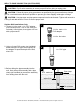
Pipe And Fittings
3. Use galvanized steel or NSF PW Schedule
40 PVC pipe and ttings. This material is
designed for water pressure and will seal
against air and water under pressure. Do
not use DWV ttings, as these are designed
for drains without pressure and will not seal
properly.
CAUTION: The entire system must be
air and water tight for efcient operation and to
maintain prime.
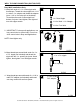
Wire Size:
The wire size is determined by the distance from
the power source to the pump motor and the
horsepower rating of the motor. See Table A for
proper wire size.
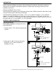
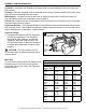
1 in. NPT
Discharge
1-1/4 in.
Suction
1 in.
Pressure
Pipe
3
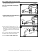
Ventilation - Ventilation and drainage must be provided to prevent damage to the motor from heat
and moisture.
Freezing - Pump and all piping must be protected from freezing. If freezing weather is forecast, drain
pump or remove completely from the system.
Water Supply - The water source must be able to supply enough water to satisfy the capacity of
pump and water needs. See performance chart on page 2.
Suction Lift - Suction lift is the vertical distance from the lowest level of the water to the pump intake.
See performance chart on page 2.
Horizontal Distance - The horizontal distance is the horizontal measurement between pump suction
and the water source. This distance may affect the ability of pump to operate. If it is more than 100 ft.,
call the manufacturer for assistance 1-800-742-5044.
GENERAL PUMP INFORMATION
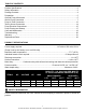
Wire Size Chart - Table A
Recommended Copper Wire and Fuse Sizes
HP Rating of Single Phase Motors
Distance from
Motor to Meter
1/2 3/4 1
0-50’
115 V
230 V
14 GA
14 GA
14 GA
14 GA
12 GA
14 GA
50-100’
115 V
230 V
12 GA
14 GA
12 GA
14 GA
12 GA
14 GA
100-150’
115 V
230 V
12 GA
14 GA
10 GA
12 GA
10 GA
12 GA
150-200’
115 V
230 V
12 GA
14 GA
10 GA
12 GA
8 GA
12 GA
200-300’
115 V
230 V
10 GA
14 GA
8 GA
10 GA
6 GA
10 GA
Fuse Size
115 V
230 V
Amps
15
15
Amps
15
15
Amps
20
15