
User guide


2. INSTALLATION
This unit is designed for under sink installation with plumb-
ing to an existing cold water line which connects to an
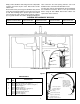
existing faucet or to a second faucet. Refer to Figure 1
which illustrates a typical installation.
Turn off water by closing the undersink shut-off valve on
the cold water side. Drain the cold water line by opening
the cold water faucet. Position the unit in an easily acces-
sible and convenient location. Cut a segment out of the
cold water line downstream from the shut-off valve so that
the filter can be plumbed in line.
The filter comes with two 3/8” O.D. polyethylene hook up
lines. The lines have fittings installed on each end but not
connected to the unit for shipping purposes. On one end of
the tubing, there is a brass union that is used to connect to
the plumbing. On the other end, there is a plastic fitting
used to connect to your filter manifold. DO NOT PLACE
THE SUPPLIED PLASTIC FERRULES ON THE END OF
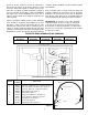
THE POLY TUBING WITH THE PLASTIC FITTING. See
Figure 2. Connect one of the plastic fittings to the filter
manifold inlet and the other to the filter manifold outlet.
Hand tighten fittings only. The filter comes factory assem-
bled to connect to 3/8” O.D. copper tubing. If existing
plumbing utilizes 3/8” O.D. polybutylene tubing, remove the
brass compression ferrules from the open ends of the
unions and replace with the supplied plastic compression
ferrules (See Figure 2.) The union connected to the side of
the filter marked “IN” can now be installed to the cold water
line coming from the water source. Push the union com-
pletely onto the cold water line and securely tighten. Next
push the union connected to the side of the filter marked
“OUT” completely on to the line going to the cold water
faucet and securely tighten the compression nut.
NOTE: If installing a secondary faucet, “tee” the inlet side
of the filter into the cold water line and connect the outlet
filter line to the second faucet.
3. STARTING THE UNIT
Close the faucet the and remove the aerator screen. Turn
on the water and slowly open the faucet a slight amount to
allow the air to bleed out. As the air is expelled and water
begins to flow smoothly, open the faucet about halfway and
allow to run. The water will appear black at first due to car-
bon particles being flushed through system. Allow the
water to run until it clears and no air is left in the line.
Replace the aerator screen.
Carbon takes a day or two to “wet out”, so periodic black
color may appear. The aerator screen may require clean-
ing, especially if pressure drop or low flow is noticed within
the first few days.
IMPORTANT: At start up, new mineral will entrain air into
the water stream. This can cause the water to have a milky
appearance. This is a normal, harmless condition that
should last no more than a few days depending upon water
usage.
4. WHEN TO REPLACE CARBON
As carbon adsorbs taste, odor and chlorine from your
water, its capacity diminishes. As the adsorptive properties
of the carbon diminish, it must be replaced. Because water
supplies across the country vary, the effective life of the
carbon depends upon the concentration of contaminants
and the amount of water that has been run through the
filter. It is recommended that the carbon and distributor
tube be replaced at least every three years. Some installa-
tions will require more frequent replacement. Use only
replacement carbon and distributor tubes designed for
your filter, and in the specified amounts. DO NOT MAKE
SUBSTITUTIONS, as there are many qualities and grades
of carbon available. A replacement carbon and distributor
tube kit (Part No. 136227) is available and should be
installed according to the replacement kit instructions.
NOTE: WHEN INSTALLING YOUR FILTER, RECORD THE
INSTALLATION DATE FOR FUTURE REPLACEMENT
REFERENCE OF FILTER (CARBON) MINERAL.
6. REPLACING MINERAL
Shut off water supply and open faucet to relieve pressure
in filter. Loosen compression nuts and disconnect unions
from plumbing. Remove entire filter from under sink and
move to outside area or place where carbon can be
replaced without worry about a small mess. Unscrew the
distributor head from the tank and pull out distributor tube.
1
UNDERSINK
TASTE AND ODOR FILTER
INSTALLATION INSTRUCTIONS
1. SPECIFICATIONS
MODEL NO. S07UF06C, TM06
APPLICATION Taste, Odor and Chlorine Removal (Wide Range of Application)
FLOW RATE 3 GPM
SPACE REQUIRED 7” X 7” X 21”
WEIGHT 13 lbs.
MAXIMUM OPERATING PRESSURE 80 PSI
MINIMUM OPERATING PRESSURE 20 PSI
TEMPERATURE 100° F
PLUMBING CONNECTION 3/8” O.D. Copper or Polybutylene
136229
SW0662
0310
Supersedes
0909