
Manual


6
INSTALLATION INSTRUCTIONS
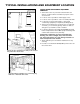
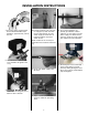
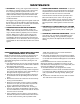
15. Check inlet and outlet for correct
water ow, matching arrows on
valve head and on by-pass valve
(especially if replacing an exist-
ing unit). CAUTION: Install in
directions of arrows.
IL0635
16. Above diagram shows unit
installed with a by-pass valve.
The unit can be removed easily
without disrupting the plumb-
ing. A 3-valve by-pass system
(Figure 18) is not needed.
Outlet
Inlet
Drain
Connection
By-Pass
Valve
IL0596
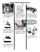
17. Above diagram shows unit with
a 3/4” manifold. This installation
requires a 3-valve by-pass sys-
tem as shown in Figure 18.
Outlet
Inlet
Drain
Connection
18. Above diagram shows a 3-
valve by-pass system. Many
new houses are plumbed water
softener ready in this manner.
A by-pass valve as shown in
Figure 16 can be used with this
system.
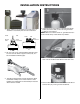
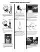
19. Before installing 3/4” ttings
to the inlet and outlet of the
by-pass valve or manifold, wrap
the threads 3 times around with
Teon tape. Install 3/4” ttings.
CAUTION: Do not over tighten.
20. Soldering is no longer required
to plumb with copper pipe.
Instead, use 3/4” compression
ttings. Connect plumbing as
required for the specic applica-
tion (see Figures 22, 23 & 24).
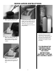
CAUTION: IF COPPER PIP-
ING WITH SWEAT FITTINGS IS
USED, DO NOT SWEAT DIRECT-
LY INTO THE IN/OUT MANIFOLD
OF SOFTENER VALVE OR BY-
PASS VALVE. HEAT WILL DAM-
AGE PLASTIC PARTS.
Inlet
Outlet
Control
Valve
Copper Pipe
Compression
Fittings
Sweat
Fittings
IL0704
Connecting to Copper Pipe
21. Turn ttings clockwise with a
wrench to tighten. Do not over
tighten.