
Manual


7
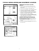
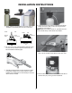
INSTALLATION INSTRUCTIONS
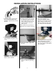
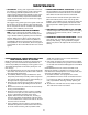
Inlet
Outlet
Control
Valve
Plastic Pipe
Solvent
Bond
Fittings
IL0705
CONNECTING TO PLASTIC PIPE
22. Turn ttings clockwise with a
wrench to tighten. Do not over
tighten.
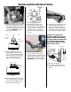
Inlet
Outlet
Control
Valve
Galvanized Pipe
or Nipple
IL0706
CONNECTING TO GALVANIZED
PIPE
23. Turn ttings clockwise with a
wrench to tighten. Do not over
tighten.
24. Typical nished installation us-
ing rigid copper pipe. Make sure
by-pass valve (if being used) is
in the service position to ensure
household service of treated
water.
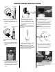
25. Press 1/2” I.D. semi-rigid or
non-collapsible plastic tub-
ing (not included) onto drain
line hose barb until snug and
secure with a hose clamp (not
included).
NOTE: Do not run 1/2” drain line
over 20’. If over 20’, increase tube
size to 3/4”.
26. Typical drain line to stand pipe
with proper 4” air gap.
NOTE: An air gap is required by
most local plumbing codes to pre-
vent waste water back ow. Check
and follow your local codes.
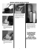
If you are installing a single tank
unit, proceed to step 33.
27. Loosen compression nut located
on right side of control valve
by turning counter clockwise.
Insert one end of 3/8” O.D. tube
(included).
NOTE: This step has already been
done on single tank design units.
Brass
Compression
Nut
Brass
Insert
Plastic
Ferrule
Poly
Tubing
IL0707
28. For 2 tank softener installations
only, make sure you have the
plastic ferrule in the right direc-
tion for an air tight seal.
29. Visually check brine tubing for
cracks or kinks. Check ttings for
proper assembly and tightness
as diagrammed.