
Manual


8
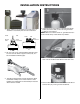
INSTALLATION INSTRUCTIONS
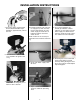
30. Turn compression nut clockwise
with wrench to tighten.
CAUTION: Do not over tighten.
NOTE: This step is not required on
single tank units.
31. Insert other end of 3/8”plas-
tic tube, from control valve,
through hole on brine
tank. Loosen compression nut,
turning counter clockwise, and
insert tubing.
NOTE: This step is not required on
single tank units.
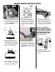
32. On 2 tank units only, turn
compression nut clockwise with
wrench to tighten.
CAUTION: Do not over tighten.
NOTE: This step is not required on
single tank units.
33. Install 1/2” I.D. semi-rigid or
non-collapsible tubing (not
included) to the overow hose
barb located on the side of the
softener cabinet or brine tank
and run to a suitable drain. Do
not connect to drain line off of
softener.
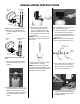
34. Plug cord from control valve
into 115V grounded electrical
outlet. Make certain that outlet
is supplied with power at all
times. Make sure area is dry
before plugging the unit in.
35. Open main water supply shut-
off valve. CHECK FOR LEAKS!
Close previously opened faucet
(step 13).
IL0635
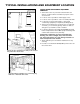
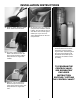
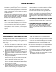
36. Make sure the bypass valve
is in the service position as
shown above. Rotate handle 90
degrees to go into the bypass
position, and close off the valve
when needed.
Outlet
Service
Position
Bypass
Valve
Inlet
37. On a 3-valve by-pass system,
open the inlet and outlet valves
and close the by-pass valve (see
diagram above).