BLOWER 1200CFM ITEM # 61022 OWNER’S MANUAL AND SAFETY INSTRUCTIONS SAVE THIS MANUAL. KEEP THIS MANUAL FOR SAFETY WARNINGS, PRECAUTIONS, ASSEMBLY, OPERATION, INSPECTION, MAINTENANCE AND CLEANING PROCEDURES. WRITE THE PRODUCT’S SERIAL NUMBER ON THE BACK OF THE MANUAL, OR THE MONTH AND YEAR OF PURCHASE IF PRODUCT HAS NO SERIAL NUMBER FOR QUESTIONS, PLEASE CALL CUSTOMER SERVICE: 909.628.
SAFETY WARNINGS Read all safety warnings and instructions. Failure to follow the warnings and instructions may result in injury and/or property damage. Save all warnings and instructions for future reference. The warning and safety instructions in this manual are not meant to cover all possible conditions and situations that may occur. Common sense, caution and care must be exercised when operating or cleaning tools and equipment.
SAFETY WARNINGS UNDERSTAND YOUR MACHINE Read this manual and labels affixed to the machine to understand its limitations and potential hazards before attempting to assemble this machine. Read, understand, and follow all instructions on the machine and in the manuals before operation. Be thoroughly familiar with the controls and their proper operation. Know how to stop the machine and disengage the controls quickly.
SAFETY WARNINGS ENGINE SAFETY If a spark arrestor is used, it should be maintained in effective working order by the operator. In the State of California the above is required by law (Section 4442 of the California Public Resources Code). Other states may have similar laws. Federal laws apply on federal lands. Never start or run the engine inside a closed area. The exhaust fumes are dangerous, containing carbon monoxide, an odorless and deadly gas. Operate this unit only in a well-ventilated outdoor area.
SAFETY WARNINGS OPERATION SAFETY Never operate the blower without good visibility or light. Always make sure you have secure footing. If you slip of fall, stop immediately. Never place any part of your body where it would be in danger if movement should occur during assembly, installation, operation, maintenance, repair, or moving. Keep all bystanders, children, and pets at least 50 feet (15m) away. If you are approached, stop the unit immediately.
PARTS INFORMATION Your walk-behind blower comes partially assembled and contains the following: 5
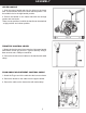
ASSEMBLY This walk-behind blower was partially assembled at the factory. To assemble your machine follow the below instructions. FRAME 1. Insert the end of the front swivel caster tube into the opening of the frame tube, align the holes. 2. Attach the tubes to the engine deck with M8x40 bolt, arc washer, spring washer and lock nut in four places. Tighten securely using two 13mm wrenches. WHEELS 1. Install one spacer onto the wheel axle. 2. Slide the wheel onto the axle. 3.
ASSEMBLY UPPER HANDLE 1. Hook the upper handle tabs into the holes on the frame tube. Use the bottom hole for the lower handle position. Use the middle hole for the high handle position. 2. Secure the handle on the frame tube with the carriage screws and star knobs. There are two positions in which the handle can be attached - a high position and a lower position. THROTTLE CONTROL LEVER 1. Mount the throttle control lever onto the right upper handle with M5x25 screw and lock nut.
SAFETY WARNINGS FRONT DISCHARGE CHUTE 1. Loosen the knob located on top of the discharge chute. 2. Orient the attachment so the “THIS SIDE UP DURING USE” is up. 3. Slide the attachment over the discharge chute. The slot on the top of the attachment will mate with the bolt of the attachment knob. 4. Hand-tighten the attachment knob to secure the attachment. The front discharge chute is used to redirect the air flow to the front of the blower. Attach it when needed.
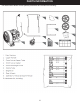
PRODUCT INFORMATION 9
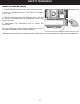
PRODUCT INFORMATION THROTTLE CONTROL LEVER Regulates the speed of engine. Moving towards H to speed up the engine. Moving towards L to lower the engine speed. RECOIL STARTER HANDLE Used to pull-start the engine. THROTTLE CONTROL The throttle control regulates the speed of the engine, and moves between FAST, SLOW and STOP positions. When the throttle control is moved to the STOP position, the engine will STOP. FLOW ANGLE ADJUSTMENT CONTROL LEVER Adjusts the direction of air flow between 7 positions.
OPERATION ADD OIL TO ENGINE 1. Make sure the walk-behind blower is on a flat, level surface. 2. Remove the oil fill cap/dipstick to add oil. 3. Using a funnel, add oil up to the FULL mark on the dipstick. (See engine manual for oil capacity, oil recommendation, and location of fill cap.) ADD GASOLINE TO ENGINE 1. The engine must be off and allowed to cool at least two minutes before adding fuel. 2. Remove the fuel filler cap and fill the tank.
SAFETY WARNINGS IDLE SPEED Set the throttle control lever to the SLOW position to reduce stress on the engine when work is not being performed. Lowering the engine speed will help extend the life of the engine, as well as conserve fuel and reduce noise level. STOP ENGINE To stop the engine in an emergency, simply turn the engine switch to the OFF position. Under normal conditions, use the following procedure: 1. Move the throttle lever to the SLOW position. 2. Let the engine idle for one or two minutes. 3.
MAINTENANCE PREVENTIVE MAINTENANCE 1. Turn off the engine. The engine must be cool. 2. Keep the engine’s throttle lever in its SLOW position and remove the spark plug wire from the spark plug and secure 3. Inspect the general condition of the blower. Check for loose screws, misalignment of binding of moving parts, cracked or broken parts, and any other condition that may affect its safe operation. 4. Remove all debris from the blower with a soft brush, vacuum, or compressed air.
MAINTENANCE ENGINE OIL/FUEL Refer to the engine manual packed separately with your unit for information on how to check or add oil/fuel and for recommendations. ENGINE MAINTENANCE Refer to the engine manual packed separately with your unit for detailed information and a maintenance schedule. STORAGE If the walk-behind blower will not be used for a period longer than 30 days, follow the steps below to prepare your unit for storage. 1. Drain the fuel tank completely.
TROUBLESHOOTING 15
PARTS INFORMATION 16
PARTS LIST 17
OF NOTE PLEASE READ THE FOLLOWING CAREFULLY THE MANUFACTURER AND/OR DISTRIBUTOR HAS PROVIDED THE PARTS LIST AND ASSEMBLY DIAGRAM IN THIS MANUAL AS A REFERENCE TOOL ONLY. NEITHER THE MANUFACTURER OR DISTRIBUTOR MAKES ANY REPRESENTATION OR WARRANTY OF ANY KIND TO THE BUYER THAT HE OR SHE IS QUALIFIED TO MAKE ANY REPAIRS TO THE PRODUCT, OR THAT HE OR SHE IS QUALIFIED TO REPLACE ANY PARTS OF THE PRODUCT.