It’s a Wireless Microph hone, Recceiver an nd Walkie ie Talkie Social Talkie E1 U User Guide e 1
Contents 1 Read before using the product ...............................................................................................................................7 1.1 Notice ..............................................................................................................................................................7 1.1.1 Liability for illegal acts ......................................................................................................................7 1.1.
2.5.2 Mounting on Camera ........ ............................................................................................................... 16 2.5.3 Magnetic board.................... ............................................................................................................... 17 2.5.4 ecklace .................................. ............................................................................................................... 18 Ne 2.
3.5.2 Move to a menu item .................................................................................................................... 24 3.5.3 Select an item .................................................................................................................................... 24 3.5.4 Adjust value ........................................................................................................................................ 25 3.5.5 Move to a position ..................
4.3.1 4.4 Up / Down .......................................................................................................................................... 34 Earset connection .................................................................................................................................... 34 4.4.1 Selecting an ear cap ....................................................................................................................... 35 4.4.2 Airtube length adjustment .........
5 4.8.6 VOX LEVEL ........................................................................................................................................... 45 4.8.7 EMERGENCY ....................................................................................................................................... 47 4.8.8 MIC GAIN ............................................................................................................................................ 50 4.8.9 RF POWER ..............
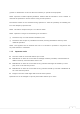
1 Read before using the product 1.1 Notice 1.1.1 Liability for illegal acts Anyone who uses this product for illegal purposes shall be liable and he or she shall be held responsible for all and any consequences. 1.1.2 FCC licensing information Federal Communications Commission statement NOTE : Change or modification not expressly approved by the party responsible for compliance could void the user’s authority to operate the equipment.
grantee or manufacturer could void the user’s authority to operate such equipment. NOTE : Exposure to Radio Frequency Radiation. Antenna shall be mounted in such a manner to minimize the potential for human contact during normal operation. The antenna should not be contacted during operation to avoid the possibility of exceeding the FCC radio frequency exposure limit. NOTE : This device complies with part 15 of the FCC Rules.
1.2 Important safeguards 1.2.1 Beware of safety accidents Check the law about radio usage before driving and using the product. Do not use the charger if the product has been hit or dropped. It may cause any possible damage or electric shock. Keep the product away from children. It can harm their safety or they may damage the product. Do not expose the product to excessive dirt or humidity. It may cause damage or electric shock.
Do not use anything too sharp, like a pencil or a needle when you push a button. It can damage the product. Clean the product on a regular basis to prevent it from being clogged with dirt. If the product is not cleaned it can damage the performance or cause malfunctions. Do not expose the product to water, alcohol or benzene. They can cause damage or electric shock.
1.3 Compo onent P Product Clip Magnetic board for the product p Earset Magnetic board for fix xing ((Including Airtube, extra ear capss) N Necklace (Lengtth adjustable e) arging cablee Cha Cable pack Qu uick start gu uide Cable pack is divide ed dependin ng on the prroduct comp position and d cable packk components are as follows.
1.4 Name of Each h Part 2 Preparre beffore U Using 2.1 Charge e Cha arge the pro oduct before use. Con nnect the ch harger to the e micro USB port. The e product be egins to charge and you u can check it by looking g at the LED D or LCD.
pops up ovver time When charging is co omplete 2.2 Green Full with th hree white ce ells Checking the battery y life fu ull middle m low empty t warning icon flashees with a beep and If remaining batterry power is very low, the i not availa ble. transmitt & receive is Charge the productt immediatelly if the warning icon starts to flash with a beep p.
umable, so iit is possible e for it to dim minish over time. If it is kept in The batttery is consu too low w or too high h temperaturres, its life span can be shortened d dramatically. 2.3 Turn on/off 2.3.1 Turn on The p power switch h is on ① As shown in n the figure above, you can push th he switch to turn the po ower on as the arrow indicates. t LED and d LCD will turn on. ② Once the power is on, the 2.3.
The buttton lock feature disables all of the b buttons, except for the power p switch h, in order to o prevent any malfuncctioning of the t product and any oth her inconven niences that may be caused by unintenttionally pressing the butttons. 2.4.1 Enable bu utton lock Push th he ‘-’ and ‘+’ button ns simultane eously for more m than 2 seconds. The follo owing icon appears a on the t screen, a beep is ge enerated, and d the button n lock is ena abled.
How w to detach it Detach it by pushin ng the clip for the produ uct down fro om the fixing g holder as the arrow in ndicates. 2.5.2 Mounting g on Camerra The e product’s clip c can be mounted m on the camera’s hot shoe as the follow wing image.
2.5.3 Magnetic board How w to put the e board onto o the producct ① Fit the magnetiic board into o the fixing holder on th he product and a then pu sh the board d upw wards until itt makes a ‘cclick’. Or, slid de the magn netic board upwards u in tthe direction n indicated with the t arrow in n the figure. ② e product ca an be fixated d to your clo othes by loca ating those two t magnet ic boards fo or the The pro oduct and fixxing your clo othes betweeen them.
If your clothes c are too t thick, th e process will w not work as described d above. Wh hen you use the magnetic boards to att ach the prod duct to yourr clothes, maake sure that you do not drop it or lo ose the mag netic board. The magnetic board d has polaritties: north and south po ole. The sam e polarities work to push aw way each oth her. Note thaat when you u follow the process abo ove.
How w to adjust the length The leng gth is adjusttable as show wn in the fig gure below.
2.6 Converrsion off Wirele ess Micrrophone and W Walkie- alkie Fun nction Ta This pro oduct can be e either used d for wirelesss microphon ne or walkie--talkie functiion. You can switch betw ween the wireless micro ophone functtion and the e radio functtion in the following f ways. 2.6.1 Press and d hold (more than 2 sseconds) ‘-‘bu utton After co onverting wa alkie talkie to o wireless m icrophone, the t screen fo or wireless m microphone appears. a 2.6.
3.1.1 Channel Displayss the channe el number cu urrently in usse. 3.1.2 Internal / External Mic M Automatically indica ates whether the devicee uses the in nternal microphone or eexternal miccrophone when ussed as a tran nsmitter. ① INT T: Uses intern nal built-in microphone m ② EXT T: Uses exterrnal microph hone (Lavalieer, etc.) 3.1.3 Battery le evel: Displayss the batteryy level in 4 steps. 3.1.
① Sing gle: Uses 1 transmitter t ② Dua al: Uses two transmitterss 3.1.6 Mic Gain / Audio ou utput levell ① Transmitter: Ind dicates Mic Gain G in 5 levvels. ② Recceiver: Indica ates audio output level iin 5 levels. 3.2 LED Indication n LED is in ndicated as the t following table depeending on th he operation n state.
② Recceiver: Opera ated with Au udio Output Level and output o sound d volume is adjustable. 3.3.2 Up / Dow wn ① Eacch time ‘+’ button n is pressed,, Mic Gain or o Audio Outtput increasees by 1 levell. ② Eacch time ‘-‘ button n is pressed, Mic Gain orr Audio Outp put decreasees by 1 level. 3.4 Conneccting Ca able 3.4.1 Transmitter Transmittter can be connected to external microphon ne such as Lavalier Micc by conneccting the enclosed d microphon ne connectio on cable.
② Con nnect the en nclosed earse et to check tthe transmittted voice. 3.5 Checklist for setting s up the menu Follow tthe direction ns below to set s up the m menu. 3.5.1 Enter the menu he menu byy pushing the t Enter th 3.5.2 ’’Menu’ button for more than 2 sseconds. Move to a menu ite em In the m menu, move from one ite em to anoth her by pushin ng the 3.5.3 ‘-’ or ‘+’ buttons. Select an item An item m in the me enu can be selected byy pushing the t ’Menu’ buttton.
3.5.4 Adjust value When a selected value v flashe es, adjust itt by pushing the 3.5.5 ‘-’ or ‘+’ buttons. Move to a position Move frrom one possition to ano other by pus hing the ’Menu’ buttons. The pre eviously sett value has been set a nd then the next value starts to flash. 3.5.6 Complete e setting ’Menu u’ button w while the set value blin nks, the blin nking stops and the If you p press the setting iis complete.
Item Tx/Rx Tx TYPE AUTO CH. CHANNEL ID RF POWER DEFAULT SET VERSION The following information describes each item’s purpose and how to set it up.
3.6 Menu setup in n detaill 3.6.1 ID Wh hat is a ‘ID’? The product to be used u as a wireless micro ophone shou uld have a sa ame ID. Thuss, the product needs to have the same ID D for transmission and reeceiving. ID is in four-digit numberss. (‘0000’ is set as th he default.) ‘ID’ setup Enter the menu by pushing the o ‘ID’ by usin ng the Move to ‘Meenu’ button for f more tha an 2 secondss. ‘-’ or ‘+’ buttons and then select by pu ushing the ‘Menu’ b button.
There iss no restriction on numb ber of receivver (Rx). When re ecording, vo oice sent from m one or tw wo receivers (Tx) can be received at multiple receiverrs at the sam me time. Tx/Rx setup Enter the menu by pushing the Move to o ‘Tx/Rx’ by using the ‘Meenu’ button for f more tha an 2 secondss. ‘-’ or ‘+’ bu uttons and th hen select byy pushing th he ‘Menu’ butto on. If the va alue flashes, adjust it by using the ‘-’ or uttons.
If the va alue flashes, adjust it by using the ‘-’ or uttons. ‘+’ bu Once ‘Txx TYPE’ has been changed, complet e it by push hing the Move to o another menu item by y using the screen b by pushing the t 3.6.4 ‘-’ or ’Menu’ b button. ‘+’ buttons or go o back to the main ’M Menu’ butto on for more than 2 seconds. AUTO CH. Wh hat is a ‘AUTO CH.’? In AUTO O CH., chann nels are auto omatically sc anned and the t optimum m channel is automatically selected d.
3.6.5 CHANNEL L Wh hat is a ‘CHA ANNEL’? When Auto A CH. is ‘O On’, channells are autom matically scan nned and ‘CH HANNEL’ do on’t appear. ‘CHANNEL’ appears onl y when Auto o CH. is ‘Offf’. When Autto CH. is ‘Offf’, the channel can be set manually. Set the same chann nel for transm mitter and reeceiver. Just change the ‘CHANNEL’ if there is to oo much noise orr you get the e line crosse ed with anotther devices. (‘01’ is sset as the de efault.
high → long sho ort low → short lon ng Adjust the setting according to your usage environmen nt and needss. (‘High’ is set as the default.) ‘RF POWER’ settup Enter the menu by pushing the f more tha an 2 secondss. ‘Meenu’ button for Move to o ‘RF POWER R’ by using the t ‘--’ or ‘+’ ‘ buttons and a then sellect by pushing the ‘Menu’ butto on. If the va alue flashes, adjust it by using the ‘-’ or uttons.
3.6.7 DEFAULT SET Wh hat is a ‘DEFA AULT SET’? All of th he values tha at have been n tuned or cchanged to meet the ne eeds of the u user will be returned to their default settings. ‘DE EFAULT SET’ setup Enter the menu by pushing the ‘Meenu’ button for f more tha an 2 secondss. Move to o ‘DEFAULT SET’ by using the ‘-’ or ‘+’ button ns and then select by pu ushing ‘Menu’ button. b the If the va alue flashes, adjust it by using the ‘-’ or uttons.
Once yo ou check the e ‘VERSION’’, move to aanother men nu item by using u the buttons or go back k to the ma ain screen b by pushing the ‘-’ or ‘+’ on for more ‘Menu’ butto e than 2 secondss. 4U Using as a Wa alkie T Talkie e 4.1 LCD (D Default set) 4.1.1 Channel Displayss the channe el number cu urrently in usse. 4.1.2 Battery le evel Displayss the batteryy level in 4 steps. 4.1.3 Talk Mode e Displayss “HALF” for half-duplex and “FULL” for full-dup plex. 4.1.
selected d voice transmission metthod. ① At PTT mode, your y voice will w be sent o only while pu ushing a PTT T button. ② VOX mode, your voice will w be autom matically reccognized and d sent. At V 4.2 LED Indication n LED is in ndicated as the t following table depeending on th he operation n state.
er in the p roduct. Com mmunication n is availablee only when you There iss no speake connectt the earset. 4.4.1 Selecting an ear cap p The earsset is a component of th he product aand the ear cap is put on o the earsett. As shown in the figure below, the airrtube can be e used if neccessary.
4.4.2 Airtube le ength adjustment Airtube length is ad djustable as shown in thee figure belo ow. Detach tthe ear buds by pulling from the tu ube as the arrrow indicate es. After, ch heck the ap ppropriate po osition for tthe user, then cut the tube with sscissors until desired length iss achieved. Insert th he ear buds back into th he part of th he tube as th he arrow indicates. 4.4.3 Connectin ng to the product p Connectt the earset to the micro o USB port i n the produ uct.
4.5 Communicatio on Transmit & receive ① ‘Tra ansmit’ mean ns to send your y voice th hrough the product p by pushing p a bu utton as con nfigured or b by recognizing your voicce. ② ‘Recceive’ means to have the product reeceive some eone’s voice that was sen nt from another pro oduct. To communicatte (default setup) ① p the PTT button to send you ur voice to a person on the Talkk to the product while pushing oth her product. Stop pushin ng the butto n when you stop talking g.
4.6 Use vib bration call The pro oduct of the other party y will make a beep tone e and vibration at the ssame time whenever w you pussh the C buttton for more e than 2 secconds. 4.6.1 Sending call c signal Sending g call signal by pushing the t ‘‘Menu’ butto on and the volume v butto on ( ‘--’ or ‘+ +’ button) simultaneously for more tthan 2 seconds. After call sound and d vibration ring, call sign nal is sent. 4.6.
4.7 Checklist for setting s up the menu Follow tthe direction ns below to set s up the m menu. 4.7.1 Enter the menu he menu byy pushing the t Enter th 4.7.2 ’’Menu’ button for more than 2 sseconds. Move to a menu ite em In the m menu, move from one ite em to anoth her by pushin ng the 4.7.3 ’Menu’ buttton. Adjust value When a selected value v flashe es, adjust itt by pushing the 4.7.5 ‘+’ buttons. Select an item An item m in the me enu can be selected byy pushing the t 4.7.
4.7.6 Complete e setting ’Menu u’ button w while the set value blin nks, the blin nking stops and the If you p press the setting iis complete. After se etting the last value, p push the ‘Menu u’ button ag gain to mo ove to the upp per level. 4.7.7 Push the e Leave the e menu ’M Menu’ button n for more t han 2 secon nds to leave the menu. You will automatically leave it iff you don’t p push any button for more than 10 sseconds. Even if you leave the menu, the values remain set.
The follo owing inform mation descrribes each ittem’s purposse and how to set it up.. 4.8 Menu setup in n detaill 4.8.1 TALK MODE Wh hat is a ‘TALK K MODE’? For com mmunication,, select TALK K MODE beffore use, term minals that want w to talkk to each oth her must be set tto the same e TALK MOD DE. There aree features in n ‘TALK MODE’: half-dup plex, full-duplex full. The follo owing inform mation descrribes the diffferent features. (‘Full-du uplex’ is set as a the defau ult.
Move to o ‘TALK MOD DE’ by using g the the ‘-’ or ‘+’ buttonss and then seelect by pusshing ‘Menu’ button. b If the va alue flashes, adjust it by using the ‘-’ or uttons. ‘+’ bu Once ‘Txx TYPE’ has been changed, complet e it by push hing the Move to o another menu item by y using the screen b by pushing the t 4.8.3 ’Menu’ b button. o back to the main ‘+’ buttons or go ‘-’ or ’M Menu’ butto on for more than 2 seconds.
Move to o another menu by using the screen b by pushing the t 4.8.4 ‘-’ or ‘+’ button ns or go bac k to the main ‘M Menu’ butto on for more than 2 seconds. ID Wh hat is a ‘ID’? If the lin ne is mixed up or the ‘CHANNEL’ is already take en by other people, set the ‘ID’. By doing so, commun nication beccomes viable between products whose ‘ID’ matches eaach other. The ‘ID’ function n has 1,000 that t range frrom 000 to 9 999. (‘000’ is set as the default.
(‘PTT’ is set as the default.) d - PTT(Push To Talk) ommunicatio on can be se ent while pusshing the PT TT button. Voice co ① Pussh the ‘PTT’ button to se end a voice. ② Talkk while holding the ‘PTT T’ button. Th his is when your y voice will be sent. ③ Sto op holding th he ‘PTT’ buttton when yo ou want to stop s sending g your voice.. - VOX(Voice Actuation) The product will reccognize yourr voice and tthen send it automatically. ‘VOX’ se ends all of the voices th hat it recogn nizes.
If the va alue flashes, adjust it by using the ‘-’ or uttons. ‘+’ bu Once ‘PT TT/VOX’ hass been chang ged, compleete it by pushing the Move to o another menu item by y using the screen b by pushing the t 4.8.6 ‘-’ or ’Menu’ button. ‘+’ buttons or go o back to the main ’M Menu’ butto on for more than 2 seconds. VOX LEVE EL Wh hat is a ‘VOX X LEVEL’? The ‘VO OX LEVEL’ enables you to o control thee sensitivity levels of rec cognized vo oices when the ‘VOX’ function n is turned on.
Move to o another menu item by y using the screen b by pushing the t ‘-’ or ‘+’ buttons or go o back to the main ’M Menu’ butto on for more than 2 seconds.
4.8.7 EMERGEN NCY Wh hat is an ‘EM MERGENCY CALL’? ‘EMERGENCY CALL’ is a functio on to make a call in an n emergency y. For examp ple, if you are a in an emergen ncy, this function helps you y send an n emergency y call to othe ers on a reg ular basis, no matter which cchannel is being b used. Those who o receive the signal can n respond tto you thro ough the terminall.
- Release an ‘EMERGENC CY CALL’ While co onnected to an emergency call, pussh PTT butto on repeatedly at a fast sspeed (5 times within one seccond) to rele ease the em mergency calll. (It is the same proce ess as when you respon nd to an emergen ncy call.) eleased from m the emergeency call, the e setup on the terminal will go back k to Once re the setttings before the emerge ncy call wass received.
If you d do not wantt to receive an emergeency call from other ID, you can d o so by settting the emergen ncy function n to off. But, for an emerrgency call from f within your y own CH HANNEL and d ID, you will alwa ays receive itt no matter if your eme rgency functtion is set to o on or off. (‘On’ is sset as the default.
‘EM MERGENCY’ setup s Enter the menu by pushing the ‘Meenu’ button for f more tha an 2 secondss. o ‘EMERGENCY’ by using g the Move to ‘-’ or ‘+’ buttonss and then sselect by pusshing ‘Menu’ button. b the alue flashes, adjust it by using the If the va ‘-’ or uttons. ‘+’ bu MERGENCY’ has been changed, com Once ‘EM mplete it by pushing the e Move to o another menu item by y using the screen b by pushing the t ‘-’ or ’Meenu’ button.
If the va alue flashes, adjust it by using the ‘-’ or ‘+’ bu uttons. Once ‘M MIC GAIN’ ha as been chan nged, compllete it by pu ushing the o another menu item by y using the Move to screen b by pushing the t ‘-’ or ’Menu u’ button. o back to the main ‘+’ buttons or go ’M Menu’ butto on for more than 2 seconds.
4.8.9 RF POWER Wh hat is a ‘RF POWER’? P The RF P POWER allow ws you to ad djust the strrength of the e transmissio on signal. Th he RF POWER can be set to o High and Low. The ran nge and avaailable talk tiime vary dep pending on the RF POW WER setting, as shown be elow. RF POWE ER Range Talk time high → long sho ort low → short lon ng nt and needss. Adjust the setting according to your usage environmen (‘High’ is set as the default.
The valu ues transmittted via the Clone Set function incclude Talk mode, m Chann nel, ID. Prod ducts are automattically synch hronized to the received d settings for call, requ uiring no seetting action ns of the users. (Default value: No) ‘CLO ONE SET’ se etup Enter the menu by pushing the ‘Meenu’ button for f more tha an 2 secondss. o ‘CLONE SE ET’ by using the Move to ‘ -’ or ‘+’ buttons and then seelect by push hing the ‘Menu’ butto on.
If the re eceiver product synchro nized alread dy, CLONED message wiill pop up without w confirm screen. 4.8.11 DEFAULT SET Wh hat is a ‘DEFA AULT SET’? All of th he values tha at have been n tuned or cchanged to meet the ne eeds of the u user will be returned to their default settings. ‘DE EFAULT SET’ setup Enter the menu by pushing the ‘Meenu’ button for f more tha an 2 secondss. o ‘DEFAULT SET’ by using the Move to the ‘-’ or ‘+’ button ns and then select by pu ushing ‘Menu’ button.
First, select ‘Yes’ to set all of th he values baack to default and then push the ‘Menu’ button. A new sscreen will pop up to confirm it. Again, sselect ‘Yes’ and then pussh the ‘Menu’ bu utton. The po ower will turrn off and on n again, initializin ng all of the e values to th heir default settings. es will return to their deffault settings. Be carefful with this feature. All of the value 4.8.12 VERSION Wh hat is a ‘VERS SION’? It is used to check the t version of o your prod duct.
Encryption: AES-128 5.1.2 Patents, Trademarks or Designs Pending This radio has one or more patents, trademarks or designs registered or pending with the United States Patent and Trademark Office or the PCT (Patent Cooperation Treaty) Office. 5.
5.3 Warranty Warrants against defects in materials and workmanship when used normally for a period of 12 months from the date of the original retail purchase by the end-user. - Those purchasing this product have to review the warranty and fill in the fields below immediately after purchasing the product. - Contact the seller or distributor after finding a problem with this product. - Make sure your claim for any repairs, replacement or refund complies with the warranty guidelines.