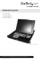
Cabinet Console 1UCABCONS 1UCABCONS17 1UCABCONS19 *actual product may vary from photo For the most up-to-date information, please visit: www.startech.
FCC Compliance Statement This equipment has been tested and found to comply with the limits for a Class B digital device, pursuant to part 15 of the FCC Rules. These limits are designed to provide reasonable protection against harmful interference in a residential installation. This equipment generates, uses and can radiate radio frequency energy and, if not installed and used in accordance with the instructions, may cause harmful interference to radio communications.
Table of Contents Introduction...............................................................................................................................1 System Requirements.............................................................................................................2 Assembly.....................................................................................................................................5 Installation....................................................................
Introduction Thank you for purchasing a StarTech.com 1U Cabinet Console. This console offers the ultimate in computer management, especially for applications where space is at a premium. The console drawer can be pulled out from the rack for operation, on sliding rails that latch in the extended position; when not in use, the Active Matrix TFT display can be folded down, locked, and secured while pushed in.
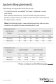
System Requirements The following are required to install the console: • 1U Cabinet Console - assembled “LCD panel + keyboard + mouse pad” drawer • Rear bracket & extension kit - This kit contains two pieces of rear brackets and two extensions. Make sure you have the correct kit to fit the depth of your cabinet.
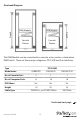
Overhead Diagram KVM Module Console Drawer Console Drawer Depth Depth KVM Module The KVM Module can be connected to a console, or be used as a stand-alone KVM Switch. There are three major categories: PS/2, USB and Sun Interfaces: Type Model name PS/2 KVM CAB832DS CAB1631D CAB1631D1U No. of Console Ports 2 1 1 No.
Type Model name Hybrid KVM CAB831HD Interface PS/2, USB No. of Console Ports 1 No. of Computer Ports 8 OSD Menu Height CAB1631HD 1 16 Yes 1U 2U PS2 – SVECONx Cable Type USB - SVECONUSx Type IP KVM Model name CAB1641HDI Interface PS/2, USB No. of Console Ports 1 No.
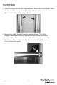
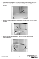
Assembly 1. Choose a proper position for the rack drawer. Mount the rear brackets (from the Rear bracket & extension kit) and lightly fasten them onto the rear vertical poles. Both will be removed later. 2. Remove the safety stopper from the console drawer. The safety stopper is designed to prevent the drawer from sliding out during transportation. Please note that once the Safety Stopper is removed, the drawer is free to slide out when the console is tilted. Be cautious, as this could cause injury.
3. Slide the assembled drawer into the rack cabinet from the front and insert the two slide rails of the assembled drawer into the pockets of the rear brackets. 4. Fasten the assembled drawer onto the front brackets using the four screws provided. 5. Remove both of the rear brackets. The front brackets now hold the assembled drawer.
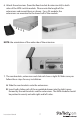
6. Attach the extensions (from the Rear bracket & extension kit) to both sides of the KVM switch module. Please note the length of the extensions and mount them as shown. For a 2U module, the extensions are mounted to the lower half of the module. NOTE: the orientation of the wide side of the extension 7. The rear brackets, extensions and slide rails have a tight fit. Make sure you follow these steps for easy installation. A. Slide the rear brackets onto the extensions. B.
8. Push the KVM switch module evenly toward the drawer: 9.
10. Make sure the C-36 connectors are firmly connected: 8mm (5/16”) C36 Connector 11. Connect the power supply to the power jack on the KVM module to complete the assembly.
Installation Please note: You can only connect to a computer using either the PS/2 or USB port not both simultaneously. Connecting to a USB Controlled Computer Connect the standard VGA cable and a USB A-B cable to the computer and 1UCABCONS as shown below. The computer can be a USB-ready PC, Sun, HP server, or a Mac.
Connecting to a PS2 Controlled Computer Connect the standard VGA cable and two mini-DIN6 male-to-male cables to the computer and 1UCABCONS as shown below. There are two mini-DIN6 female connectors marked with keyboard and mouse, be sure not to swap the connections. Male-to-Female HDB15 for VGA Connecting to a KVM Switch When cascading with a KVM switch, 1UCABCONS can be used to control up to 16 computers.
Operation 1 2 3 4 10 5 6 7 8 9 Front Panel Functions KVM Control and Status: (This section is effective only when a KVM switch module is connected.) 1. Computer Selection Pad - Press one of these pushbuttons to select a computer. For 16 port models, 1-8 represent the lower 8 ports, while A-H indicates the higher 8 ports. Port 1 and A share the same push button; if port 1 is already selected, tap its pushbutton to select port A.
9. Scroll Lock - Keyboard Scroll Lock status 10. LCD Panel Power Switch Keyboard Replacement The keyboard is replaceable, in the event of language changes or maintenance. To replace the key-board, tilt it up, locate the mini-USB cable underneath the keyboard and unplug it gently. While installing the replacement keyboard, please ensure that you extend just enough of the cable to keep the keyboard flat inside the tray.
Touchpad Replacement The built-on Touchpad offers “wheel mouse” functionality. The area of the Touch Pad to the right side of the two small triangular marks is the simulated “wheel” as shown below: Triangular Marker Scroll Wheel Area Left Mouse Button Right Mouse Button To remove the Touch Pad, press the tab underneath it upward to release the latch, then slide it outwards until the Touch Pad can be lifted up clear from the notches, as shown in the figure below (right side).
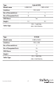
Specifications Active Display Area (mm) Pixel Pitch (mm) Resolution 1UCABCONS 1UCABCONS17 1UCABCONS19 304.1 x 228.1 337.920 x 270.336 376.32 x 301.056 0.297(H) x 0.297(V) 0.264 (H) x 0.264 (V) 0.294(H) x 0.294(V) 1024 x 768 @60/70/75Hz 1280 x 1024 @60/70/75Hz RGB vertical strip Color Pixel Arrangement Normally White Display Mode Brightness (cd/m2) Contrast Ratio Display Color 250 (center) 350 (center) 350:1 1000:1 16.
Technical Support StarTech.com’s lifetime technical support is an integral part of our commitment to provide industryleading solutions. If you ever need help with your product, visit www.startech.com/support and access our comprehensive selection of online tools, documentation, and downloads. Warranty Information This product is backed by a one year warranty. In addition, StarTech.
StarTech.com has been making “hard-to-find easy” since 1985, providing high quality solutions to a diverse IT and A/V customer base that spans many channels, including government, education and industrial facilities to name just a few. We offer an unmatched selection of computer parts, cables, A/V products, KVM and Server Management solutions, serving a worldwide market through our locations in the United States, Canada, the United Kingdom and Taiwan. Visit www.startech.