Power Remote Control 8 Outlet AC Remote Power Control Switch with Serial Interface PCM815SHNA Instruction Manual
FCC Compliance Statement This equipment has been tested and found to comply with the limits for a Class B digital device, pursuant to part 15 of the FCC Rules. These limits are designed to provide reasonable protection against harmful interference in a residential installation. This equipment generates, uses and can radiate radio frequency energy and, if not installed and used in accordance with the instructions, may cause harmful interference to radio communications.
Instruction Manual Table of Contents Introduction . . . . . . . . . . . . . . . . . . . . . . . . . . . . . . . . . . . . . . . . . . . . . . . . . . . . .1 Before You Begin . . . . . . . . . . . . . . . . . . . . . . . . . . . . . . . . . . . . . . . . . . . . . . . .1 System Requirements . . . . . . . . . . . . . . . . . . . . . . . . . . . . . . . . . . . . . . . . . .1 Contents . . . . . . . . . . . . . . . . . . . . . . . . . . . . . . . . . . . . . . . . . . . . . . . . . . . . .
Instruction Manual Introduction Thank you for purchasing a StarTech.com remote power control switch. This product is the perfect complement to our IP-based Server Remote Control product line or can be used as a standalone power management solution. Using a serial interface, you can remotely manage the power status of up to eight devices.
Instruction Manual Site Preparation Considerations PLEASE READ: IMPORTANT To avoid overloading the power management switch and exceeding the electrical tolerances of your site, it is important that you know the power consumption requirements of the devices you will be connecting before attempting an installation of this product. Most items have their power consumption characteristics printed on the outside of the device, on the power adapter (if applicable), or in their documentation.
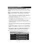
Instruction Manual 2. Safely power down the devices you wish to connect to the switch. 3. Connect the power plug for each device to OUTLET 1 through OUTLET 8 on the rear panel of the switch. 4. You can power on each device by pressing the corresponding white button on the front panel of the switch. When powered, the green on status LED will light underneath each button on the front panel.
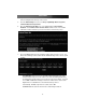
Instruction Manual The front panel is an easy way to determine the power status of the devices connected to the switch and and the overall power load being experienced by the switch at any time. The following is an explanation of the buttons and indicators on the front panel: CURRENT: The measurement of the current power load of the switch measured in amps.
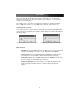
Instruction Manual 4. Login to the Server Remote Control as admin. Choose the Admin/Setup option from the navigation bar at the top of the screen. 5. From the Admin/Setup menu, choose Setup compatibility with host system, external KVM, external power bar. 6. Go to the External Power Bar menu. The default setting is None/Feature disabled. Select Remote Power Control Switch from the menu. The unit will activate the feature and return you to the menu after a short refresh period. 7.
Instruction Manual Management Option II: Management Software The management software allows you to power devices attached to your switch(es) on and off and program advanced timer features to automate power events. Please see Appendix A, “Configuring Your Computers for Remote Restarts” for important additional information.
Instruction Manual The main menu of the management software is a graphical representation of the front panel of the bank 01 switch unit and any switches cascaded to it. The information displayed corresponds to the physical front panel of the switch(es). See the previous section for more information. The software uses a “short form” to identify ports and banks on prompts and dialog boxes. 0105 refers to bank 1, port 5; 1202 refers to bank 12, port 2 (and so on).
Instruction Manual The General tab The General Tab Select Com Port: This option changes the serial port that the host computer will use to connect to the switches. You can select Auto (recommended) or choose a serial port number from 1 to 8. Auto-connect ioPower on Start: When checked, forces the management software to connect to the switch(es) automatically. If disabled you must choose Connect from the Setting menu to begin a session. The setting is unchecked by default.
Instruction Manual Bank and Port: Specifies which switch (the bank) and what port on that bank that the power event applies to. A setting of 0 means “all” in the software. For example, bank 0, port 0 will apply the action to all ports on all banks. Bank 2, port 0 will apply the event to all ports on bank 2. You cannot use a port setting other than 0 when the bank setting is 0 (i.e. bank 0, port 2, meaning port 2 on every switch). If that situation occurs, the software will ignore the event.
Instruction Manual Management Option III: Terminal Session Since the power switch uses a serial interface, you can also manage it using a terminal session through your preferred communications software (HyperTerminal, xterm).
Instruction Manual Once you exit serial command mode, you have to hit [Enter] twice again to restart the serial command mode.
Instruction Manual The clock uses 24-hour format: 5:00 pm is the same as 17:00 EW – Timer Activate every week at a specific time point Examples: EW 1 4 ON 1 01:22:50 – Set timer to power on port 4 on bank 1 every Monday at 01:22:50. EW 1 0 ON 3 00:10:00 – Set timer to power on all ports on bank 1 every Wednesday at 00:10:00. EW 0 0 OF 5 01:00:00 – Set timer to power off all ports on all cascaded banks every Friday at 01:00:00.
Instruction Manual SETTIME 2004/09/27 18:10:00 – Set up the system Date and time to be 2004/09/27, 18:10:00 GETTIME – Get System Time Example: GETTIME VER – Firmware Version Examples: VER 01 – Show the firmware version of bank 1 VER 16 – Show the firmware version of bank 16 VER 00 – Show the firmware version of all banks 13
Instruction Manual Troubleshooting Problem: One or more red ALARM LEDs is lit on the front panel of a switch. Cause: The port(s) displaying the error have experienced a hardware problem. Correction: Power the problem port(s) and or the switch on and off 2-3 times. If this does not correct the problem, contact Technical Support. Problem: The CURRENT indicator on the front panel is flashing. Cause: The unit is experiencing a small overload.
Instruction Manual Specifications Input Voltage 100~240 VAC @ 50~60 Hz Output Voltage 100~240 VAC @ 50~60 Hz (Depends on power input) AC Output Outlets 8 Front Panel Controls 8 x Power On/Off Current Load Indicator (amps) Bank Number Indicator 8 x Power LED 8 x Alarm State LED Host Computer Interface RS-232 Serial User Interface Front Panel Power Switch Management Software Max. Combined Switches 16 units via UTP Cable Cascade Cascade Interface 1 x RJ-45 (input) 1 x RJ-45 (output) Max.
Instruction Manual Technical Support StarTech.com’s lifetime technical support is an integral part of our commitment to provide industry-leading solutions. If you ever need help with your product, visit www.startech.com/support and access our comprehensive selection of online tools, documentation, and downloads. Warranty Information This product is backed by a one-year warranty. In addition, StarTech.
Instruction Manual Appendix A: Configuring Your Computers for Remote Restarts Since most current computers use “intelligent” power supplies that have advanced power management capabilities, once they are powered off from the switch their BIOSes must be configured to return to a powered state when power is restored. Most computers have a hardware configuration utility (usually called “setup”) that you can access during the startup process by pressing a key or combination of keys on the keyboard.
Revised: 17 February 2005 (Rev.