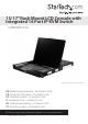
U 17” Rack Mount LCD Console with Integrated 16 Port IP KVM Switch CABCONS1716I *actual product may vary from photos DE: Bedienungsanleitung - de.startech.com FR: Guide de l'utilisateur - fr.startech.com ES: Guía del usuario - es.startech.com IT: Guida per l'uso - it.startech.com NL: Gebruiksaanwijzing - nl.startech.com PT: Guia do usuário - pt.startech.com For the most up-to-date information, please visit: www.startech.
FCC Compliance Statement This equipment has been tested and found to comply with the limits for a Class B digital device, pursuant to part 15 of the FCC Rules. These limits are designed to provide reasonable protection against harmful interference in a residential installation. This equipment generates, uses and can radiate radio frequency energy and, if not installed and used in accordance with the instructions, may cause harmful interference to radio communications.
Table of Contents Introduction.............................................................................................1 Packaging Contents.................................................................................................................................. 1 System Requirements............................................................................................................................... 2 Assembly..............................................................................
Changing Your Configuration................................................................................................................ 40 Optimizing video performance............................................................................................................ 41 Using the Advanced Video Tuning feature....................................................................................... 42 Using the Modem Feature.....................................................................
Introduction This 1U Rack Mount LCD KVM Console features an integrated 16 Port Multi-Platform IP KVM Switch module, 17in active matrix LCD monitor, 105-key keyboard and mouse touchpad neatly combined into 1U of space in any standard rack or cabinet 30in (or greater) in depth.
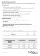
System Requirements Depending on your needs, you may require one or more of the following cables: All applications • StarTech.com part number: M45PATCHxxxx 1 x Straight-through Ethernet patch cable (to connect the unit to your LAN) • StarTech.com part number: SVECONxx StarTech.com PS/2 3-in-1 KVM Cables (1 for each managed computer ) • StarTech.com part number: SCNM9FF StarTech.com 10 ft. Cross Wired Serial/Null Modem Cable DB9 F/F • StarTech.com part number: SVECONUSXX StarTech.
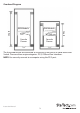
Overhead Diagram KVM Module Console Drawer Console Drawer Depth Depth KVM Module The KVM Module can be connected to a console, or be used as a stand-alone KVM Switch. There are three major categories: PS/2, USB and Sun Interfaces. NOTE: You can only connect to a computer using the PS/2 port.
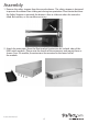
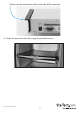
Assembly 1. Remove the safety stopper from the console drawer. The safety stopper is designed to prevent the drawer from sliding out during transportation. Please note that once the Safety Stopper is removed, the drawer is free to slide out when the console is tilted. Be cautious, as this could cause injury. 2. Attach the extensions (from the Rear bracket & extension kit) to both sides of the KVM switch module. Please note the length of the extensions and mount them as shown.
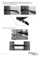
Please note the orientation of the wide side of the extension 3. Fasten the console to the rack, using the provided screws.
4. Slide the rear bracket into both sides of the unit, ensuring the three round screws are INSIDE the bracket track, while sliding inward (noting the arrows in the diagram below). 5.
6. Push the KVM switch module evenly toward the drawer: 7.
8. Make sure the C-36 connectors are firmly connected: 8mm (5/16”) C36 Connector 9. Connect the power supply to the power jack on the KVM module to complete the assembly.
Hardware Guide Front Panel Functions 1 2 3 4 10 5 6 7 8 9 KVM Control and Status: (This section is effective only when a KVM switch module is connected.) 1. Computer Selection Pad - Press one of these pushbuttons to select a computer. For 16 port models, 1-8 represent the lower 8 ports, while A-H indicates the higher 8 ports. Port 1 and A share the same pushbutton; if port 1 is already selected, tap its pushbutton to select port A.
Keyboard Status and LCD Panel Power Switch: 1. Num Lock - Keyboard Num Lock status 2. Caps Lock - Keyboard Caps Lock status 3. Scroll Lock - Keyboard Scroll Lock status 4. LCD Panel Power Switch Rear Panel Functions 1 2 3 4 5 6 7 8 9 10 11 1. DC In 2. Link 3. Serial Port 4. VGA Out 5. R-Port 6. IP Setup button - Pressing this button (using a paperclip, etc.) will automatically load the On-Screen Display. 7.
Network Configuration CABCONS1716I offers four distinct methods for configuring the unit for your network. Which method will work best depends on your level of experience and your specific network configuration. NOTE: Connecting the remote computers prior to following the steps outlined below can result in system instability. Please refrain from connecting the remote computers, until the local peripherals have been connected.
If static IP addresses are assigned, you will likely need to change the Net Mask, IP Address and other details, prior to connecting via your Web browser. If this is the case, connect a local PS/2 keyboard and press the Enter key. In order to proceed, you will require an administrative username and password. By default, the username and password are admin. You will be given the opportunity to change the password (recommended) to be performed once the configuration is complete.
log, since you will need to know the IP address of the unit to complete the configuration over your Web browser. (If you are unsure of how to access your network’s DHCP log, contact your System Administrator for details.) If the unit is powered on and connected to the network via the LAN port on the rear panel, it will automatically attempt to lease an IP address using DHCP.
Web Configuration Using Static IP Unlike the DHCP access method described above, some networks rely on static IP addresses wherein every device has a pre-configured IP address that does not change. To access the Web configuration for this product, you will need to configure the workstation you are using to the same subnet (255.255.255.0) and also assign it a valid IP address (i.e. 192.168.1.100).
You can use the serial port on the CABCONS1716I to access the terminal configuration tool; to do so, you will require a null modem serial cable. Connect a female end of a serial cable to the serial port used for serial access on the host computer. Connect the opposite end to the CABCONS1716I. Configure the terminal software with “8N1” settings: Connection speed: 115200 bps No.
Using the Web Interface The Web interface is the most intuitive way to configure the CABCONS1716I. As it offers a Java-based VNC client that can be used to control the host computer from a remote location, as well as support for any industry-standard HTML Web browser. You can access the Web interface by opening your Web browser and entering the IP address of the CABCONS1716I you wish to configure.
Navigating the Web Interface Name Help Area Main Menu After the inital login, the screen is divided into several sections, three of which will remain on the screen at all times while viewing the Web Interface: Name: At the top of the screen, the name of the machine being controlled is displayed Main Menu: At the left-most side of each page, the Main Menu is displayed, allowing users to choose functions offered by the Web Interface.
NOTE: The aforementioned sections of the Web Interface will remain on-screen, with selected categories displayed center screen. Main Menu selections NOTE: Some of the following items may not be present, based on assigned user privileges (i.e. non-admin users will not see any items under the Admin category).
Snapshots: The Snapshots screen allows you to view and save a screenshot of the controlled computer in its current state. This screenshot will update periodically (automatically). Saved image files are stored in .PNG format. Logout: Clicking on Logout will terminate your Web Interface section. To re-initiate the Web Interface, you will be required to re-enter your username and password.
When disabled, the LAN port will use the values assigned to it on the IP Addresses and Routing table below. IP Addresses and Routing: This table allows you to assign IP information for the LAN and WAN ports separately. If you are using DHCP, the values for the LAN port will be filled in automatically and any changes made will not affect the setup. Domain Name Server: This section allows you to specify DNS servers and the default DNS domain suffix in use on the network.
System Ident: Machine Name: This is the name that is used to uniquely identify this machine.You might want to create a DNS entry that matches this name. The name is provided as the Client Name for the DHCP server. It is also shown at the top of each page in the web browser interface and is the “desktop name” for VNC clients. Other identification details: These values are for information pur poses. They are visible from the VNC client and via SNMP (if enabled). Location: This string is sent as the system.
SNMP: The SNMP menu allows you to configure the CABCONS1716I so it can be recognized and managed using industry standard Simple Network Management Protocol software. RADIUS: The RADIUS server requires the IP address, the UDP port number (1812 default or 1645) and the shared secret. The shared secret is used to encrypt communications and corresponds to a shared password for the RADIUS server and the client machine. Two additional servers may be defined for backup purposes.
If the computer you are using to view this page knows the correct time, just press the button to set the time and date to the same time as your browser. Firmware: The firmware on the Server Remote Control is field upgradeable. To upgrade to another version, login as admin. Auto Self Upgrade: The CABCONS1716I unit is able to upgrade itself over the Internet.
NOTE: Remember the following during the firmware upgrade: • DO NOT turn off power to unit before this operation completes successfully. • The unit will sometimes reboot as part of the upgrade procedure, depending on which system component is upgraded.You will have to reconnect and re-login in those cases. • Wait at least two minutes after pressing Start. Do not assume the upload did not work, the upload could simply be slow. • Each distributed file upgrades a different component of the system.
Using the Terminal Interface via Serial Port The terminal interface can be accessed via the serial port for configuration of the basic settings of the CABCONS1716I. While not intended to be a substitute for the Web interface, it does allow you to configure similar functions. The menu list below describes the options that can be modified through the terminal interface. NOTE: You must use the W option to confirm and apply any changes made before you exit the terminal session.
Native VNC Client This system implements the VNC protocol, so any off-the-shelf VNC client can be used. There are several different VNC clients available, all of which should work with this system, as the system automatically detects and makes use of certain extensions to the basic RFB protocol as provided by the VNC clients. The best client currently is TightVNC (http://www.tightvnc.com). Binaries are available for Windows, Linux, MacOS and many versions of Unix.
• Some Unix versions of the VNC client have integrated SSH tunneling support. Some clients require your local user id to be the same as the userid on the system. Use a command like this: vncviewer -bgr233 -tunnel 10.0.0.34:22 Using the VNC Menu One of the unique features of this product is the VNC menu system. Whenever you see a window with a dark blue background and grey edges, this window has been inserted into the VNC data stream so that it is effectively laid over the existing video.
Bandwidth: Indicates current average bandwidth coming out of the Server Remote Control unit. The second number measures round trip time (RTT) of the connection when it was first established. Resync: Re-aligns the remote and local mouse points so they are on top of each other. Redraw: Redraws the entire screen contents; occurs immediately. PS/2: Resets the PS/2 keyboard and mouse emulation. Useful to recover failed mouse and/or keyboard connections in PS/2 mode.
Main Menu To access the main menu, quickly press F7 twice.You must press the key twice within one second. If you press it once or too slowly, then the F7 key(s) are sent to the host, just like any other key. This is the only way to get into the menu system, if the Bribar is disabled. Here is the main menu for a typical system: The main menu window may be moved by clicking and dragging on the title bar. It can be closed by pressing Esc, or by clicking on the red X in the top right corner.
• Mouse Resync: Resynchronizes the mouse pointer so that the local and remote mouse pointers are on top of each other. • PS/2 Reset: Resets the PS/2 emulation going to the host and to the attached PS/2 devices. This can be used if the mouse stops responding or the PS/2 keyboard isn’t working. • Take Control: When multiple users are connected to the same system, use this button to take control away from another user. Only one user may control the keyboard and mouse at any time.
VirtKeys Menu Clicking any button in the top half of the window simulates pressing and releasing the indicated key. In the bottom area of the screen, clicking will simulate the indicated Meta key being pressed.You may then click in the top part to send another key and release the Meta key at the same time. Alternatively, you may move the mouse outside this window, press the regular key, and then choose -RESET- to release all depressed keys. The VirtKeys menu can be left open while using the host system.
Video Tuning menu Use the Auto Everything button to automatically fine-tune all three adjustments. If the test pattern for Color Offset calibration is not present on the screen, then the Color Offset adjustment is skipped. Changes/frame indicates the number of 16x16 blocks of video that are being sent, on average, for every frame of video. With a static image being displayed by the server, this number will be zero (shown as -nil-).
If the system cannot find the test pattern on the screen, check that the pattern isn’t scaled or covered up. (perform this operation in 24-bit or 32-bit color video mode (i.e. truecolor). Although the algorithm may work in 16-bit or 8-bit color video modes, the results will not be optimum and usually it won’t be able to recognize the test pattern. Pressing the Advanced button will open the Advanced Video Tuning menu.
Accessing KVM Features Once you can access and configure the networking component of the Server Remote Control, you can use it to select and control the managed computers connected to it. This section describes how to add additional KVM switches to the master unit for greater flexibility, and how to use the on-screen display (OSD) system to manage your computers. Once you have established a VNC session, you can access the KVM features as though you were at a local console.
OSD Operations By hitting the left key twice within two seconds, you may see the ‘Hotkey Menu’ if it is enabled (an OSD option). Or, by hitting the left key three times within two seconds, you will see a KVM MENU screen (below) showing a list of the computers with corresponding channel addresses, names and status. • The port number (or channel address) of the currently selected computer is displayed in red in the top right of the screen.
OSD Function Keys You can use the function keys when the OSD menu is active. The Function key edits the name of a managed computer or a Slave KVM. First, use the and arrow keys to highlight a channel then press followed by name entry. Your name can be up to 14 characters long. Valid characters are A to Z, 0 to 9, and the dash character. Lowercase letters are converted to uppercase. Press to delete a letter one at a time.
Manual Scan: Scans through powered computers using keyboard control. Scan Type (: More\Scan Type) determines if scanned computers must also be eye mark selected. Press the up arrow key to select the previous computer and the down arrow key to select the next computer. Press any other key to abort the Manual Scan mode. Audio Stick: A multimedia module can be LINKed to the back of each KVM for selecting microphone and stereo speaker signals. There are two options for Audio Stick: On and Off.
Keyboard Speed: The KVM offers a keyboard typematic setting that overrides the typematic settings in the BIOS and Windows operating system. Available speed options are Low, Middle, Fast and Faster as 10, 15, 20 and 30 characters/sec respectively. The Keyboard Speed setting is retained in non-volatile memory. Hotkey Menu: When you hit the left key twice within two seconds, the Hotkey Menu appears displaying a list of hot-key commands if the option is On.
Hot Key Commands A hot key command is a short keyboard sequence to select a computer, activate a computer scan, etc. A hot-key sequence starts with two Left Control keystrokes followed by one or two more keystrokes. The short form hot-key menu can be turned on as an OSD function (: More\ Hotkey Menu) every time the left key is pressed twice. Left refers to the key located at the left side of the keyboard.
Manual Scan: Manual Scan enables you to manually switch back and forth between powered computers: left Ctrl + left Ctrl + F2. Press the up or down arrow to select the previous or next computer in sequence. Press any other key to abort the Manual Scan. NOTE: The Scan Type setting will determine whether computers must be eye-marked to be included in the scan.
Optimizing video performance Choose the best video mode We recommend using a display resolution of 1024x768 @60Hz refresh rate, as facilitates fitting multiple windows on your remote desktop. Higher refresh rates put unnecessary stress on the quality provided by the video card, and do not provide any additional information or benefit. Noisy video cards A digital KVM works by converting the analog video signals emitted by your video card into digital data.
Using the Advanced Video Tuning feature The Advanced Video Tuning menu allows you to adjust the qualities of the video in your VNC sessions, and can be accessed by clicking the Advanced button on the Video Tuning VNC menu. While many users will probably allow the CABCONS1716I to automatically configure the video properties, you can use this menu to exercise a great deal of control over the settings if required. The Presets section contains up to sixteen different settings, plus the factory setting.
The Performance section of the screen gives an indication of the quality of the video. Changes/frame is the average number of tiles that change for each frame sampled by the hardware. Flatness is an indication of what percentage of the screen contains tiles that are comprised of only one color. The Regrab Screen button in the Actions section causes the screen to be re-captured.
Connecting a Modem Modem Connection The CABCONS1716I will work with virtually any Hayes-compatible modem capable of recognizing the standard AT command set.
Modem configuration Although most connections will work appropriately with the default settings on CABCONS1716I, manual changes can be made. To do so: Login to the Web interface as Admin. Click Modem, listed on the left side of the main page. You will then be presented with the Modem Option menu (see above). Make the following changes to enable and configure the modem connection: 1. Enable modem connections (PPP) via serial port/modem: select Enabled. 2.
Configuring the Remote Connection This section describes how to configure a typical Windows dial-up session to access the modem connection on the CABCONS1716I. The instructions here relate to a Windows XP configuration; other versions of Windows are similar. 1. Open My Network Places from the desktop or the Start menu. 2. Click View network connections. 3. Click Create a new connection under Network Tasks. 4. The New Connection Wizard window will open. Click Next. 5.
• PPP (Point-to-Point Protocol) must be used; no other authentication methods are supported. • TCP/IP must be installed/enabled on the computer making the connection, and must be used for the dial-up connection. • The connection must be configured to obtain a dynamic IP address. • The user name/password must match a user currently configured on the CABCONS1716I. • For best performance and to simplify the troubleshooting process, firewall software should not be used with the dial-up connection.
Performance Notes • All images over the PPP connection will be grayscale to conserve bandwidth. If other users are connected while a PPP session is active, their screens will be in grayscale as well. When PPP is inactive, color is automatically re-enabled. • Some areas of the screen may not be updated as frequently as others, and animations or other auto-updating areas of the screen may appear out-of-focus or “blocky” as a result.
Modem Troubleshooting Guide The following messages will appear in the system log on the Status screen in the Web interface and may help to diagnose problems with the modem configuration. Starting PPP (for auth) on port… Modem is connecting and the PPP login process is starting. Modem hang up. Resetting The connection has been closed or terminated unexpectedly. Timeout during login process.
Connecting Serial Remote Control Modules to the CABCONS1716I The cable for each serial device is similar to a phone cable and uses an RJ-14 connector. For the first module, connect the cable (provided) to the R-Port on the rear panel of the CABCONS1716I. Connect the opposite end to the DATA OUT (or similar) port on the Serial Remote Control unit. Note that some devices may use an integrated cable, so you will not need to make a separate connection on the serial device.
8N1: Eight bits, no parity, one stop bit (default and most common) 7N1/701/7E1/7M1/7S1: Seven bits, (none/odd/even/mark/space) parity, one stop bit 8N1/801/8E1/8M1/8S1: Eight bits, (none/odd/even/mark/space) parity, one stop bit 8N2: Eight bits, no parity, two stop bits Force DCD: Forces the Carrier Detect signal to be active at all times. Normally, DCD becomes active when a new user connects and is dropped when the last user disconnects (a response that is similar to many modems).
You are now connected to the R-Port module in a live terminal session. Commands you type will be echoed on the terminal screen. The module also offers a simple menu system that allows you to change configuration settings (similar to the function of the menus in a terminal software package). Press [Ctrl] - [Shift] – [_] (underscore) on the keyboard to access the menu.
Operating Notes: • If the power supply to the R-Port modules you have connected becomes faulty (short, overload) then the R-Port LED on the front panel of the CABCONS1716I will show red. • Under normal operations, this light should remain green. The R-Port connector on the rear panel also has an LED that mirrors the status of the light on the front panel. • Hardware handshaking (CTS/RTS) is required for speeds exceeding 9600 bps.
About Security Certificate Warnings What is a security certificate? Sites that employ secure TCP/IP (Internet) connections include a certificate that confirms that users are connecting to a legitimate site and are not being redirected without their knowledge. Certificates are issued by trusted third parties called Certificate Authorities (CAs) and contain essential details about a site that must match the information supplied to your Web browser.
Installing the new certificate… The following instructions detail how to install the certificate from the CABCONS1716I onto your local computer (in this case, when using Internet Explorer with Windows XP): 1. Open your Web browser and go to the CABCONS1716I login screen. Click the Update security certificate link. 2. When prompted, choose Open. 3. A Window will appear that offers information about the certificate. Click Install Certificate. 4. The Certificate Import Wizard will appear.
After resync, the mouse pointers are still not aligned Use the video adjust menu to position your video image exactly where required. Normally, a slight video positioning error is perceived as a mouse sync issue. A video positioning error is visible as a black line along the top or bottom (and right or left) edges of the remote screen. Remember to save your position changes! Cannot login via SSH Remember to use either admin or a username created in the system as the user name you give your SSH client.
Keyboard Replacement The keyboard is replaceable, in the event of language changes or maintenance. To replace the key-board, tilt it up, locate the mini-USB cable underneath the keyboard and unplug it gently. While installing the replacement keyboard, please ensure that you extend just enough of the cable to keep the keyboard flat inside the tray.
Touchpad Replacement The built-on Touchpad offers “wheel mouse” functionality. The area of the Touch Pad to the right side of the two small triangular marks is the simulated “wheel” as shown below: To remove the Touch Pad, press the tab underneath it upward to release the latch, then slide it outwards until the Touch Pad can be lifted up clear from the notches, as shown in the figure below (right side). The Touchpad is attached by a piece of mini-USB cable.
Specifications Console Connectors VGA (1), PS/2 Mouse (1), PS/2 Keyboard (1) Display Colors 16.
Technical Support StarTech.com’s lifetime technical support is an integral part of our commitment to provide industry-leading solutions. If you ever need help with your product, visit www.startech.com/support and access our comprehensive selection of online tools, documentation, and downloads. For the latest drivers/software, please visit www.startech.com/downloads Warranty Information This product is backed by a three year warranty. In addition, StarTech.
Hard-to-find made easy. At StarTech.com, that isn’t a slogan. It’s a promise. StarTech.com is your one-stop source for every connectivity part you need. From the latest technology to legacy products — and all the parts that bridge the old and new — we can help you find the parts that connect your solutions. We make it easy to locate the parts, and we quickly deliver them wherever they need to go. Just talk to one of our tech advisors or visit our website.