In-Band OAM Gigabit Ethernet to MM LC Fiber Media Converter - 550m, Metal Housing ET91000LCOAM *actual product may vary from photos DE: Bedienungsanleitung - de.startech.com FR: Guide de l'utilisateur - fr.startech.com ES: Guía del usuario - es.startech.com IT: Guida per l'uso - it.startech.com NL: Gebruiksaanwijzing - nl.startech.com PT: Guia do usuário - pt.startech.com For the most up-to-date information, please visit: www.startech.
FCC Compliance Statement This equipment has been tested and found to comply with the limits for a Class B digital device, pursuant to part 15 of the FCC Rules. These limits are designed to provide reasonable protection against harmful interference in a residential installation. This equipment generates, uses and can radiate radio frequency energy and, if not installed and used in accordance with the instructions, may cause harmful interference to radio communications.
Table of Contents Product Overview...................................................................................1 Side 1.............................................................................................................................................................. 1 Side 2.............................................................................................................................................................. 1 Introduction..............................................
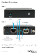
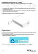
Product Overview Side 1 DC Jack Side 2 RJ-45 Default (Use to recover from lost password or to return all settings to factory default values) Power FX Speed LAN Speed LC Connector FX Link LAN Link The LAN Speed and FX Speed LEDs use 2 colors to indicate speed. Green indicates Fast Ethernet (100Mbps), while Yellow indicates Gigabit Ethernet. When the LEDs are off, it indicates a speed of 10Mbps.
Introduction Packaging Contents • 1x Fiber Media Converter • 1x Universal Power Adapter (NA/UK/EU) • 1x Instruction Manual System Requirements • 1000BASE-T compatible Ethernet network equipment • RJ45 terminated UTP Cat5e or better Ethernet cable • Available AC electrical outlet Factory Reset Procedure Apply power to the unit and allow approximately 30 seconds to fully boot. Using a pencil or a ball-point pen, press the “DEFAULT” push button located on the face plate and hold it for 6 seconds.
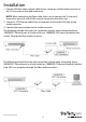
Installation 1. Connect the fiber optic network cable from a computer/switch/media converter to the LC connector on the media converter. NOTE: When connecting the fiber cable, make sure to connect the Tx (transmit) terminal on one end, with the Rx (receive) terminal on the other end. 2. Connect a UTP Ethernet cable, from a computer/switch to the RJ45 jack on the media converter. 3. Connect the power adapter to the media converter.
Installation into ETCHS2U Chassis The ETCHS2U chassis supports the full line of StarTech.com ET series 2 media converters, which can be installed in a mixed fashion to suit your environment. The cards are designed to be hot-swappable, meaning the chassis need not be powered off in order to remove or insert a card. 1. If the chassis slot was previously unused, loosen the screw at the top of the slot to remove the cover plate 2.
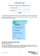
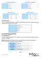
The configuration webpage will appear with the following section down the left side. Each can be expanded to reveal several configuration options and tool, which will be explained in the following pages System Information Section Network Information The information displayed on this page gives specific device information, network information, and port status for the local ET91000LCOAM and for any remote unit that is accessible via IEEE802.3ah OAM in-band management.
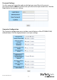
DD Information The DD or DDOM information is read from the MSA compliant SFP module and can be displayed via the web user interface. Local Settings Section IP Configuration Use this screen to configure TCP/IP settings for the local unit. Click the Apply button to save your settings. Note: Changing the IP address will cause you to lose your remote management session until you re-connect at the new address.
Password Settings Use this screen to change the web console login password. Key in the current password (Default: admin) and then enter your desired new password twice. Click the Apply button to save your settings. Converter Configuration The Converter configuration menu includes special features of the ET91000LCOAM, defined below. Click the Apply button to save your settings.
Management - (Default: Enabled) If disabled, all management communication with a remote converter will be stopped. Only normal Ethernet transmission will occur without any possibility of remote management through 802.3ah OAM. Jumbo Frames (9k byte packets) – (Default: Disabled) Enable to add Jumbo Frame support. Note: Jumbo frames can only work on a pure Jumbo frame network where all devices support it.
Port Configuration Use this screen to configure the Ethernet (TP) and the optical port (FX). Options include enabling / disabling the port, setting auto or forced Ethernet mode, enabling 802.3x (flow control), and setting ingress and egress rate limiting. Note: Rate limiting has a granularity of 64K so the rate can be set from 64k to 1000M in 64K steps. Click the Apply button to save your settings. MIB Counters Reports packet statistics on all interfaces of the device.
VLAN Group Configuration ET91000LCOAM supports up to 16 VLAN groups. By using the check boxes for each port, the access to different VIDs can be controlled. Click the Apply button to save your settings. Per Port Configuration ET91000LCOAM actually has three different ports: the external copper, external fiber, plus the internal CPU port. The VLAN Per Port Setting page deals with how frames exit (egress) the copper, fiber and CPU (management).
The following operations may be performed to the outgoing frames: 1. Replace Tag - The device will remove VLAN tags from packets then add new tags to them. The inserted tag is defined in ”VLAN Group Index”. 2. Remove Tag - The switch will remove VLAN tags from packets, if they are tagged. The switch will not modify packets received without tags. 3. Add Tag - The switch will add VLAN tags to packets, if they are not tagged when these packets are output on this port.
Q in Q or double VLAN tagging is defined in IEEE802.1ad. Double VLAN tagging is required when a service provider wishes to carry a customer’s VLAN tagged traffic through its own VLAN network. In MEF (Metro Ethernet Forum) terms, the first tag or “inner tag” is referred to as the C-tag (customer) while the second tag or “outer tag” is referred to as the S-tag (service provider). Normal VLAN tag has an EtherType (TPID or Tag Protocol Identifier) of 0x8100. The IEEE802.
Note: To use the OAM functions, the 802.3ah Functions setting must be Enabled (Default: Disabled). 802.3ah Mode – (Default: Passive) Used to configure an OAM pair. In a pair, one unit must be ‘active’, while the other must be ‘passive’. Typically the remote converter (CPE) would be in ‘passive’ mode and the local in ‘active’. Link Events – Enable / Disable reporting of Link Events via OAM.
Errfrmsec_Win (Error Frame Seconds Summary Window) – (Default: 10) This window of time can be adjusted from 10 to 900 seconds. This is the "Window" used to gather error frame seconds (the number of 1-second intervals with at least one frame error). Errfrmsec_Thr (Error Frame Seconds Summary Threshold) - This threshold count can be set from 5 up to 2 x 10¹⁶. This count in conjunction with the frame seconds window, will determine if the Error Frame Seconds Summary event is reported via OAM.
Tools Section System Reboot When the converter is rebooted, all counters and registers are cleared and the converter starts fresh. If OAM is enabled, the discovery process will start. After selecting the System Reboot menu item, a confirmation dialogue box will pop up. Click “OK” to reboot the converter or click “Cancel” to leave without rebooting. Note: The converter requires about 20~25 seconds to fully reboot.
Save and Restore After configuring the converter, the entire configuration can be saved as a backup file using the SaveToFlash button. Once saved, the configuration file can be loaded at any time using the LoadFromFlash button. To restore all settings to factory default, click the ResetToFactory button. Note: The IP address will also be reset to default (10.1.1.1), so you may lose management contact with the converter.
Logging Out Click the Logout button at the bottom of the web interface to terminate your session. Once logged out, the username / password will be required to login again.
Specifications Supported Standards IEEE 802.3, 802.3u, 802.3ab, 802.3z, 802.3ah, 802.
Technical Support StarTech.com’s lifetime technical support is an integral part of our commitment to provide industry-leading solutions. If you ever need help with your product, visit www.startech.com/support and access our comprehensive selection of online tools, documentation, and downloads. For the latest drivers/software, please visit www.startech.com/downloads Warranty Information This product is backed by a two year warranty. In addition, StarTech.
Instruction Manual 20
Hard-to-find made easy. At StarTech.com, that isn’t a slogan. It’s a promise. StarTech.com is your one-stop source for every connectivity part you need. From the latest technology to legacy products — and all the parts that bridge the old and new — we can help you find the parts that connect your solutions. We make it easy to locate the parts, and we quickly deliver them wherever they need to go. Just talk to one of our tech advisors or visit our website.