5 Port Unmanaged Industrial Gigabit Ethernet Switch IES51000 *actual product may vary from photos DE: Bedienungsanleitung - de.startech.com FR: Guide de l'utilisateur - fr.startech.com ES: Guía del usuario - es.startech.com IT: Guida per l'uso - it.startech.com NL: Gebruiksaanwijzing - nl.startech.com PT: Guia do usuário - pt.startech.com For the most up-to-date information, please visit: www.startech.
FCC Compliance Statement This equipment has been tested and found to comply with the limits for a Class A digital device, pursuant to Part 15 of the FCC rules. These limits are designed to provide reasonable protection against harmful interference when the equipment is operated in a commercial environment. This equipment generates, uses and can radiate radio frequency energy and, if not installed and used in accordance with the instruction manual, may cause harmful interference to radio communications.
Table of Contents Introduction.............................................................................................1 Packaging Contents.................................................................................................................................. 1 System Requirements............................................................................................................................... 1 Product Diagram.......................................................................
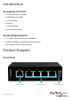
Introduction Packaging Contents • 1 x Industrial Ethernet Switch • 2 x Wall-Mount Brackets • 1 x DIN-Rail Clip • 4 x Screws • 1 x Terminal Block • 1 x Instruction Manual System Requirements • 12 – 58V DC power source (terminal block) • 10/100/1000 Mbps compatible network devices • Cat5 or better UTP Ethernet cabling Product Diagram Front View Uplink Port Instruction Manual Device Ports 1 LED Indicators
Top View DIP Switches Ground Connector Redundant Terminal Block Power w/ Alarm Relay LED Indicators 1 x P1 (Power) 1 x P2 (Power) 1 x ALM (Alarm) Solid (Green): Power is connected and functioning Off: No power input detected Solid (Green): Power is connected and functioning Off: No power input detected Solid (Red): Power failure detected Off: No alarm / alarm disabled Solid (Green): Link detected (no traffic) 5 x Link / Act Flashing: Activity Off: No Link detected 5 x Speed Instruction Manual Solid
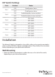
DIP Switch Settings Pin # Pin 1 Pin 2 Pin 3 Pin 4 Pin 5 Pin 6 Position Status ON Enable power alarm OFF Disable power alarm ON Enable broadcast storm rate limit OFF Disable broadcast storm rate limit ON NOT USED OFF NOT USED ON NOT USED OFF NOT USED ON NOT USED OFF NOT USED ON NOT USED OFF NOT USED Installation The Network Switch is designed to sit on a flat surface, or be securely mounted to either a wall or DIN-Rail using the included brackets.
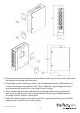
143.2 29.1 136.2 89.4 2. Determine the desired location and orientation of the switch on the wall, and mark the bottom mounting notch location. 3. Depending on the mounting surface, use the appropriate tools and hardware to install a mounting screw into the wall. There should be a gap of approximately 2 mm between the head of the screw and the wall surface. 4.
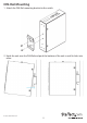
DIN-Rail Mounting 1. Attach the DIN-Rail mounting bracket to the switch. 2. Hook the unit over the DIN-Rail and push the bottom of the unit in until it clicks into place.
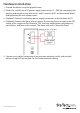
Hardware Installation 1. Ground the device using the ground screw. 2. Power the switch from a DC power supply (input range 12 – 58V) by connecting the positive and negative wires into the V+ and V- contacts of P1 on the terminal block and tightening the wire clamp screws. 3. (Optional) Connect a redundant power supply connection to the contacts for P2. 4. (Optional) Connect the alarm relay as shown.
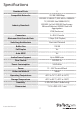
Specifications Number of Ports 5 Compatible Networks 10/100/1000 Mbps IEEE 802.3 10BASE-T, IEEE 802.3u 100BASETX, IEEE 802.3ab 1000BASE-TX, Industry Standards IEEE 802.1p QoS, IEEE 802.3az EnergyEfficient Ethernet, IEEE 802.3ad Link Aggregation Connectors 5 x RJ-45 Female Maximum Data Transfer Rate 2 Gbps (Full-Duplex) Switching Architecture Store-and-Forward Buffer Size 128 KB Full Duplex Yes Auto MDIX Yes Jumbo Frame Support Up to 9000 bytes Flow Control IEEE 802.
Technical Support StarTech.com’s lifetime technical support is an integral part of our commitment to provide industry-leading solutions. If you ever need help with your product, visit www.startech.com/support and access our comprehensive selection of online tools, documentation, and downloads. For the latest drivers/software, please visit www.startech.com/downloads Warranty Information This product is backed by a two year warranty. In addition, StarTech.
Hard-to-find made easy. At StarTech.com, that isn’t a slogan. It’s a promise. StarTech.com is your one-stop source for every connectivity part you need. From the latest technology to legacy products — and all the parts that bridge the old and new — we can help you find the parts that connect your solutions. We make it easy to locate the parts, and we quickly deliver them wherever they need to go. Just talk to one of our tech advisors or visit our website.