
Quick Start Guide


Instruction manual
DE: Bedienungsanleitung - de.startech.com
FR: Guide de l'utilisateur - fr.startech.com
ES: Guía del usuario - es.startech.com
IT: Guida per l'uso - it.startech.com
NL: Gebruiksaanwijzing - nl.startech.com
PT: Guia do usuário - pt.startech.com
Manual Revision: 09/01/2015
For the latest information, technical specications, and support for
this product, please visit www.startech.com/MCM1110MMLC.
Packaging contents
• 1x ber media converter - MM LC
• 1x universal power adapter (NA/EU/UK/AU)
System requirements
• 10/100/1000Mbps Ethernet network equipment
• RJ45 terminated UTP Cat5e or better Ethernet cable
• Terminated ber optic cable — Multimode LC duplex
connectors
• AC electrical outlet
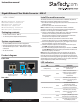
Product diagram
Front view
MCM1110MMLC
Gigabit Ethernet Fiber Media Converter - MM LC
LEDs LFP DIP
switch
Gigabit SFP transceiver
module - 850nm - LC
RJ45
port
DC input port
Install the media converter
The media converter is pre-installed with a 1000Base-SX (850nm)
Gigabit SFP transceiver module with LC connectors.
1. Turn o the networking equipment that will be connected to the
media converter.
2. Remove the dust cover from the SFP module.
Note: In addition to the pre-installed SFP module, the media
converter can also be used with any MSA-compliant Gigabit SFP
module. It will not support 10/100Mbps modules.
3. Connect a multimode LC duplex ber-optic cable from the media
converter’s SFP module to your ber network device.
The TX and RX connectors must be paired at both ends of the
connection For example TX to RX, and RX to TX.
4. Connect an RJ45 Cat 5e/6 Ethernet cable from the media
converter’s RJ45 port to your 10/100/1000Mbps network device.
5. Select the appropriate regional clip for your region and connect
the power adapter to an AC electrical outlet.
6. Connect the power adapter to the media converter’s DC input.
The PWR LED (power) should light up solid.
7. Turn the networking equipment from step #1 back on. The Fiber
and TP LNK/ACT LEDs should light up solid when all cables and
devices are properly connected.
Note: Check the link budget of your SFP modules, as well as the
module’s intended wiring distance. SFP modules are designed to
transmit signals over large distances. If the physical wiring distance
is too short, the transmitting optical signal (laser) may be too strong
and damage the receiving SFP module. An in-line optical attenuator
may be required to protect them from damage.
LED indicators
LED Status Indication
PWR (Green) Solid
The media converter is
powered on
Fiber LNK/ACT
(Green)
Solid
A ber link between the
media converter and ber
network equipment is
established
Flashing
The ber port is actively
sending or receiving data
(activity)
TP LNK/ACT (Green)
Solid
An RJ45 Ethernet link
between the media
converter and RJ45 network
equipment is established
Flashing
The RJ45 port is actively
sending or receiving data
(activity)
TP 1000 (Green)
Solid
A Gigabit (1000Mbps) link on
the RJ45 port is established
O
The RJ45 port is running at
10/100Mbps speeds
Rear view