NETRS2321POE Instruction Manual Ethernet Device Server 1-Port Industrial RS-232 Ethernet Device Server - Power over Ethernet
FCC Compliance Statement This equipment has been tested and found to comply with the limits for a Class B digital device, pursuant to part 15 of the FCC Rules. These limits are designed to provide reasonable protection against harmful interference in a residential installation. This equipment generates, uses and can radiate radio frequency energy and, if not installed and used in accordance with the instructions, may cause harmful interference to radio communications.
Table of Contents Hardware Guide................................................................ 2 Package Contents........................................................................2 Front Panel...................................................................................2 Rear Panel....................................................................................3 LED Indicators..............................................................................3 Hardware installation...............
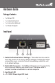
Hardware Guide Package Contents • 1 x Driver CD • 1 x Industrial Switch • 1 x Instruction Manual • 1 x Power Adapter Front Panel 1 2 3 4 1. Switch to Restore Default Settings - This switch can be used to reset the product to its factory default settings. Pressing the switch using either a pen or similar tool will immediately restore the unit to its default settings. 2. RJ45 LAN Connector - 10/100Mbps Ethernet port.
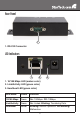
Rear Panel 1 1. RS-232 Connector LED Indicators 1 2 3 1. 10/100 Mbps LED (amber color) 2. Link/Activity LED (green color) 3. Heartbeat LED (green color) LED Name Colour Function 10/100 Mbps Green On: 100Mbps. Off: 10Mbps. Link/Activity Green On: Linked. Blinking: Transfering Data. Heartbeat Amber Blinking: Normal Operation. Not Blinking: Malfunction.
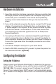
Hardware installation 1. Use static electricity discharge precautions. Remove possible static discharge potential from any objects that the adapter may come in contact with prior to installation. This can be accomplished by touching a bare metal chassis rail after you have turned off the power. 2. If you will be externally powering the device, connect the DC power adapter.
1. Setting the IP Address from a DHCP Server A DHCP server will automatically assign an IP address (dynamic address) as well as Subnet Mask and Gateway to this adapter. If you power up the Adapter without a fixed (static) IP address, the DHCP server will be able to assign an IP address (Note: By default, DHCP is disabled. If you wish to support DHCP, Enable it in the Adapter Setup Menu). Note: If you will set the IP address using another method, you will need to use a static IP address.
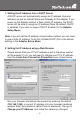
3. Setting the IP Address using the Em.exe Utility The Em.exe is a Microsoft Windows based utility used to identify the adapters connected on the same subnet and network segment. To run the Em.exe utility, please insert the driver CD supplied with the Adapter. Open the program at the following location (assume the CD-ROM drive is at E): E:\IO_over_IP\Utilities\Em\Em.exe Managing the Adapter Settings When you enter the Adapter Setup Menu, the following page will be available for your access.
Controller Setup Menu Items Menu Item Description IP Address 4 numbers separated by dots. If enabled, these can be assigned by the DHCP server. Subnet Mask 4 numbers separated by dots. If enabled, these can be assigned by the DHCP server. Gateway Address 4 numbers separated by dots. If enabled, these can be assigned by the DHCP server. DHCP Client If disabled, the IP address, Subnet mask and Gateway address must be assigned manually.
Menu Item Description Socket Port of HTTP Setup If disabled, the IP address, Subnet mask and Gateway address must be assigned manually. Socket Port of Serial I/O Port Number: Any number between 1 and 65536,except 80 and 8080 (these have been designated as the web pages). Socket Type: TCP Server - Uses TCP protocol, passively waits for Client. TCP Client - Uses TCP protocol, actively connects to Server. UDP Client - Uses UDP protocol, exchanges packets with Server without connection.
Menu Item Description Packet mode interpacket timeout In packet mode, the time constant used to determine if the packet is finished. Acceptable range is 10 to 1000 ms. Device ID User assigned device ID number. Acceptable range is 0 to 65535. Report device ID when connected If this function is enabled, the device will report the device ID after the socket is connected.
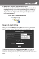
Installing the VSP Virtual COM Port Driver 1. Locate the necessary Software in the following folder on your driver CD. The VSP COM.exe is the redirector software. The Em.exe is used to setup the hardware mode to support VSP redirector. 2. Configure your hardware mode to support VSP. • Run the EM.exe application to find the device hardware. • Enter the setup menu by double clicking the listed hardware. • Click Login (by default settings, there is no password).
• Change the settings to COM Port, save the changes, and exit the setup menu. 3. Run the VSP Setup Program. • Double click the VSP COM.exe application in the VSP folder on the supplied CD. You may receive a message indicating that this driver has not yet passed Windows logo testing. If so, click Continue Anyway.
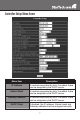
• Set the COM Port settings: The following figure shows only one COM port setting being changed. You may have 4 COM ports (or 1, 2 ports depending on the model), you will need to set it 4 times for, once for each COM port.
Specifications Specification NETRS2321POE LAN Connector RJ45 Speed 10/100Mbps RS-232 Number of Ports 1 x RS-232 Signals TXD, RXD, RTS, CTS, DTR, DSR, DCD, GND Connector DB9 Male (RS-232) Parity None, Odd, Even Data Bits 6, 7, 8 Stop Bits 1, 2 Speed 300 to 115.2Kbps Power Requirements Power Input 12V DC (via DC Jack), or 48V DC (via Ethernet Cable, PoE model only) Power Consumption 110mA @ 12V DC Mechanical Specifications Material Metal Gross Weight 250.5g (0.
Specification NETRS2321POE Environmental Operating Temperature 0 to 55C (32 to 131F) Storage Temperature -20 to 85C (-4 to 185F) Operating Humidity 5 to 95% RH 14
Technical Support StarTech.com’s lifetime technical support is an integral part of our commit-ment to provide industry-leading solutions. If you ever need help with your product, visit www.startech.com/support and access our comprehensive selection of online tools, documentation, and downloads. Warranty Information This product is backed by a one year warranty. In addition, StarTech.
StarTech.com has been making “hard-to-find easy” since 1985, providing high quality solutions to a diverse IT and A/V customer base that spans many channels, including government, education and industrial facilities to name just a few. We offer an unmatched selection of computer parts, cables, A/V products, KVM and Server Management solutions, serving a worldwide market through our locations in the United States, Canada, the United Kingdom and Taiwan. Visit www.startech.