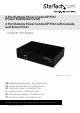
2 Port Remote Power Control IP PDU (Power Distribution Unit) 2 Port Remote Power Control IP PDU with Console and Sensor Ports PDU02IP / PDU02IPSC *PDU02IP shown in photo DE: Bedienungsanleitung - de.startech.com FR: Guide de l'utilisateur - fr.startech.com ES: Guía del usuario - es.startech.com IT: Guida per l'uso - it.startech.com NL: Gebruiksaanwijzing - nl.startech.com PT: Guia do usuário - pt.startech.com For the most up-to-date information, please visit: www.startech.
FCC Compliance Statement This equipment has been tested and found to comply with the limits for a Class B digital device, pursuant to part 15 of the FCC Rules. These limits are designed to provide reasonable protection against harmful interference in a residential installation. This equipment generates, uses and can radiate radio frequency energy and, if not installed and used in accordance with the instructions, may cause harmful interference to radio communications.
Table of Contents Product Diagram.....................................................................................1 Rear View....................................................................................................................................................... 1 Front View..................................................................................................................................................... 1 Introduction......................................................
Firmware Upgrade Procedure...............................................................22 Specifications...........................................................................................23 Technical Support...................................................................................24 Warranty Information.............................................................................
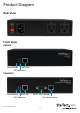
Product Diagram Rear View Front View PDU02IP Reset Button RJ45 LAN LED Indicators PDU02IPSC Reset Button RJ45 LAN RS232 UPS Console LED Indicators Instruction Manual Dry Contact Input 1
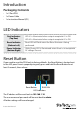
Introduction Packaging Contents • 1 x 2 Port PDU • 1 x Power Cable • 1 x Instruction Manual (CD) LED Indicators Port Indicators (Top Row) LED #1 is illuminated when output receptacle #1 is ON. Reset Indicator (Bottom Left) Reset LED will flash when the Reset function is being performed. Power Indicator (Bottom Right) Utility Power LED is illuminated when there is an acceptable AC voltage Present. LED #2 is illuminated when output receptacle #2 is ON.
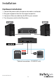
Installation Hardware Installation 1. Connect the power cord to the power inlet and to a wall outlet 2. Plug your equipment into the two output receptacles 3. Connect an Ethernet cable from the PDU to your network 4.
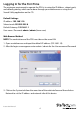
Logging In for the First Time The minimum requirement to operate the PDU is to setup the IP Address, subnet mask, and default gateway, which can be done through your web browser or using the IP Search Utility application on the CD. Default Settings: IP address: 192.168.1.10 Subnet mask: 255.255.255.0 Default Gateway: 192.168.1.1 User name / Password: admin / admin (lower case) Web Browser Method NOTE: The workstation and the PDU must be on the same LAN 1.
IP Search Utility NOTE: The workstation and the PDU must be on the same LAN for the IP Search Utility to detect it, and the Windows Firewall must also be turned off. 1. Open the Windows Control Panel 2. Select Windows Firewall 3. Select Off and then click the OK button 4. Insert the provided CD in the CD-ROM drive 5. Launch the IP Search Utility program 6. Click on the Refresh button to search for all PDU02IPxx units on the LAN 7.
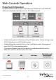
Web Console Operation Power Switch Operation The global outlet controls can be used to either turn all outlets on, or all outlets off, while each individual outlet allows for On / Off / Reboot controls. • Double clicking the ALL ON button will turn ON both outlets. Double clicking on the ALL OFF button will turn OFF all of the outlets. • Double clicking the switch for Port 1 or Port 2 will flip the switch to the opposite state (ON/OFF) for that individual outlet.
Monitor Section The Monitor section shows you the current status of each outlet and allows you to modify the power state of each outlet individually, or make global changes to both. From the Monitor tab you can also Schedule events and configure the Auto-Ping feature. Configuration Tab Click on the Set button located on the top corner of each outlet to modify an individual outlet. When the Set button is orange, the outlet is ready to be configured.
Schedule Tab Configure scheduled actions for each outlet. Click on the Set button located on the top corner of each outlet to modify an individual outlet. When the Set button is orange, the outlet is ready to be configured. Recurrence: An Action can be scheduled to occur yearly, monthly, weekly or daily at a specific time for each individual outlet. Time: Set the time (hours and minutes) when you want the action to occur. Action: Set the action you want the outlet to perform, ON, OFF or Reboot.
UPS Status (PDU02IPSC Only) The UPS Status information will display to the left of the power switches on the Monitor Tab. If you have connected an APC Smart UPS series device to the RS232 port on the PDU02IPSC, you can monitor the following information about your UPS. Alive - Displays the state of the UPS device as either Normal (1) or Offline (0). Model - Displays the connected UPS model.
Dry Contact Input Indication (PDU02IPSC Only) The dry contact status information will display to the right of the power switches on the Monitor Tab. If you have connected and configured the Detectors information (located in System > Detectors section – explained in the following pages), you will see a Normal or Abnormal indication. Status Illustration: Normal Abnormal System Section Network Tab Configure the PDU with a Static IP address or use DHCP.
Http Port: Assign the desired HTTP port (default is port 80) for connecting to the PDU via a web browser. If you change the HTTP port, enter the IP address followed by the new HTTP port into your browser address bar (e.g. http://192.168.1.10:8080). Save: Saves all changes. Mail Server Tab Configure the Mail Server settings to send notifications when an event has occurred. SMTP Server Address: Enter the Hostname or IP address of the SMTP Mail Server that will be used to send emails from the PDU.
SMS Server Tab Configure the SMS Server settings to send text notifications when an event has occurred. Server Address: Enter the SMS server address. Port: Enter the port number for the SMS server. The default value is 2500. Equipment Name: Enter a name/subject to identify the device. Account: Enter the account name if required. Password: Enter the password if required. Send SMS: Check this box if SMS Server requires authentication to send messages.
SNMP/SysLog Tab Configure SNMP Traps and System Logs to be sent to different Network Management Stations (NMS). System Name: Enter the name of the SNMP device. System Contact: Enter the name of the System Administrator. System Location: Enter the location of the SNMP device. Receiver IP Address: The IP Address of the NMS of where the Traps should be sent. Receiver Port: The port that will be used to receive the Traps. The default value is 162.
Detectors Tab (PDU02IPSC Only) Other Tab Set the outlets on the main tab to default to a reboot action, instead of ON/OFF. Reboot Option: Check this box to default to rebooting the outlet instead of just turning the outlet ON/OFF. The Reboot check box on the Monitor screen will be checked when this option is selected. Reboot Device: Selecting this option will immediately reboot the outlets. Save: Saves all changes.
Firewall Section This menu allows the administrator to configure user privileges and prevent unauthorized access to the device. IP Filter Tab Configure the range of IP addresses that are able to access the PDU. IP Filter Enable: Check this box to enable the IP address filter. Allow IP Address: The first four sections are the beginning of the IP range. The last section is the ending of the IP range that is being given access to the device. E.g. To authorize the IP range from 192.168.1.110 - 192.168.1.
MAC Filter Tab Configure a specific list of MAC addresses that are able to access the PDU. MAC Filter Enable: Check this box to enable the MAC address filter. Allow MAC Address: Enter the MAC address of the user(s) that you want to have access to the PDU. The default MAC address is the MAC address of the computer that you initially used to setup the device. ADD: Click ADD to place the entered address in the table. Delete: To delete a specific MAC address, click on the “X”. Save: Saves all changes.
Account Section This menu allows the administrator to setup authorized user accounts and other privileges. The administrator can assign specific access levels for each user account. Example: The administrator can assign user “A” to have access to outlet number 1 and receive email notifications when an event occurs to that specific outlet. Smart Power 2S allows administrator to set up 2 accounts for management. Account: Enter the user id for each user account.
TimeSync Section This menu allows the administrator to set the date and time for the PDU. Equipment Date: Displays the date. This field is not editable. Equipment Time: Displays the time in 24-hour format. This field is not editable. Sync with PC: Check the Sync with PC button to synchronize the PDU’s date and time with the PC. PC Date: The current PC system date. PC Time: The current PC system time.
Manual Setup: Check the Manual Setup button to manually setup the date and time. Date: Please enter the date with correct format. Time: Please enter the time with correct format. Time Zone: Adjust the time difference between Greenwich Mean Time and your country into this format. Save: Saves all changes. Event Section This menu displays the events that have occurred with the PDU. Refresh: Check for new events. Download: Save the event log information (.csv format). Delete: Clear the event log.
To Download / save the configuration file: 1. Click the Download button, then select Save from the window that pops up 2. Select the location you would like to place the file (.
To upload a previously saved configuration file: 1. Click the Browse button 2. Navigate to the location of your previously saved cfg.bin file, the click Open 3. Click the Upload button to begin.
Firmware Upgrade Procedure 1. Open the firmware_upgrade.exe program located on the included CD 2. Input the IP Address of the PDU 3. Click on the GetVersion button 4. Click on the browse (…) button to select the new firmware file (.bin) 5. Input the password (default is admin) 6. Click on the Upgrade button to start the process 7. Once the firmware upgrading process is complete, the PDU will reboot 8.
Specifications PDU02IP PDU02IPSC Ports 2 1 - IEC 60320 C14 Power Plug 1 - IEC 60320 C14 Power Plug Connectors 1 - DB-9 (9 pin; D-Sub) Male 1 - RJ-45 Female 2 - RJ-45 Female 2 - NEMA 5-15 Power (North America) Receptacle 2 - NEMA 5-15 Power (North America) Receptacle Max. Current load per Port 8A Max. Total Current Output 12 A Power Consumption 4.
Technical Support StarTech.com’s lifetime technical support is an integral part of our commitment to provide industry-leading solutions. If you ever need help with your product, visit www.startech.com/support and access our comprehensive selection of online tools, documentation, and downloads. For the latest drivers/software, please visit www.startech.com/downloads Warranty Information This product is backed by a two year warranty. In addition, StarTech.
Hard-to-find made easy. At StarTech.com, that isn’t a slogan. It’s a promise. StarTech.com is your one-stop source for every connectivity part you need. From the latest technology to legacy products — and all the parts that bridge the old and new — we can help you find the parts that connect your solutions. We make it easy to locate the parts, and we quickly deliver them wherever they need to go. Just talk to one of our tech advisors or visit our website.