Outdoor 300Mbps Wireless N Access Point - 2T2R 5GHz R300WN22OP5 / R300WN22OP5G / R300WN22OP5E *actual product may vary from photos DE: Bedienungsanleitung - de.startech.com FR: Guide de l'utilisateur - fr.startech.com ES: Guía del usuario - es.startech.com IT: Guida per l'uso - it.startech.com NL: Gebruiksaanwijzing - nl.startech.com PT: Guia do usuário - pt.startech.com For the most up-to-date information, please visit: www.startech.
FCC Compliance Statement This equipment has been tested and found to comply with the limits for a Class B digital device, pursuant to part 15 of the FCC Rules. These limits are designed to provide reasonable protection against harmful interference in a residential installation. This equipment generates, uses and can radiate radio frequency energy and, if not installed and used in accordance with the instructions, may cause harmful interference to radio communications.
Déclaration d’exposition à la radiation: Cet équipement respecte les limites d’exposition aux rayonnements IC définies pour un environnement non contrôlé. Cet équipement doit être installé et mis en marche à une distance minimale de 20 cm qui sépare l’élément rayonnant de votre corps. L’émetteur ne doit ni être utilisé avec une autre antenne ou un autre émetteur ni se trouver à leur proximité.
Table of Contents Introduction.............................................................................................2 Packaging Contents.................................................................................................................................. 2 System Requirements............................................................................................................................... 2 Product Overview......................................................................
Introduction Packaging Contents • 1 x Outdoor Access Point • 1 x PoE Injector • 1 x Metal Hose Clamp • 1 x Power Adapter • 1 x Instruction Manual System Requirements • A networked computer system with a Java-enabled web browser (for configuration) • Cat 5 (or better) network cabling from PoE Injector to Wireless AP and PoE Injector to LAN Switch/router (no more than 100m total) • Mounting screws / anchors for wall mounting PoE Injector and/or Wireless AP Instruction Manual 2
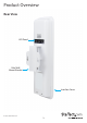
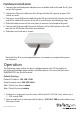
Product Overview Rear View LED Panel Pole/Wall Mount Bracket Interface Cover Instruction Manual 3
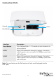
Connection Ports LAN 1 Ground LAN 2 Reset Button Interface Description Reset Button Press continually for 5 ~ 10 seconds to reset the device to factory defaults LAN 1 Allows LAN connection through a Category 5 (or better) cable. Supports auto-sensing for 10/100Mbps speeds and half/ full duplex LAN 2 Allows LAN connection through a Category 5 (or better) cable.
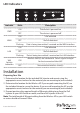
LED Indicators Indicator PWR WAN LAN Wifi Activity Indicators State Description ON The device is powered on OFF The device is powered off ON Link detected OFF No link detected Flashing Data is being transmitted / received on the WAN interface ON Link detected OFF No link detected Flashing Data is being transmitted / received on the LAN interface ON OFF Wireless client(s) are connected.
Hardware Installation 1. Connect the included power adapter to an available wall outlet and the DC jack on the PoE injector. 2. Connect an Ethernet cable from the LAN port of the PoE Injector to your LAN switch or router. 3. Connect a second Ethernet cable from the PoE port of the PoE Injector, the other end of this cable will connect to the AP as instructed in the following steps. 4. Slide the bottom cover of the unit down to remove it and expose the ports. 5.
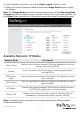
3. Enter the default username / password (admin / admin) and press Enter. 4. Select your desired Operation Mode and click the Change Mode button to apply the change. Note: The Change Mode button will automatically jump you to the Operating Mode Settings page for the mode you have selected. In future visits to the web interface, use the Setup button located next to the mode to open that mode’s configuration page.
5. From the Settings menu for each mode, you can access the applicable Wireless and Security settings. To configure wireless security, click the Setup button beside the Security option. Note: It is strongly recommended to configure security, to avoid unwanted access to your wireless network. 6. Click the Save & Restart button once you have finished configuring the device to apply the settings. 7.
8. To restrict access to the web interface of your AP, it is also recommended to configure a password, which can be done by selecting Password Settings from the left column of the web interface. Click the Save & Change button to apply your changes.
Specifications Supported Wireless Standards IEEE802.11 a/n Chipset Atheros - AR9344 Connectors 2 x RJ45 Ethernet Female Antenna Configuration 2x2:2 (TxR:s) Antenna Type 14dBi Dual Polarization Directional Antenna Wireless Frequency Range 5.150GHz ~ 5.850GHz Wireless Bandwidth 20/40MHz 64/128 bit WEP WPA(TKIP with IEEE 802.1x) Wireless Encryption Supported WPA2(AES with IEEE 802.1x) WPA -PSK Maximum Wireless Distance 3km* 802.11n : (40MHz) : up to 300Mbps Maximum Data Transfer Rate 802.
Technical Support StarTech.com’s lifetime technical support is an integral part of our commitment to provide industry-leading solutions. If you ever need help with your product, visit www.startech.com/support and access our comprehensive selection of online tools, documentation, and downloads. For the latest drivers/software, please visit www.startech.com/downloads Warranty Information This product is backed by a two year warranty. In addition, StarTech.
Hard-to-find made easy. At StarTech.com, that isn’t a slogan. It’s a promise. StarTech.com is your one-stop source for every connectivity part you need. From the latest technology to legacy products — and all the parts that bridge the old and new — we can help you find the parts that connect your solutions. We make it easy to locate the parts, and we quickly deliver them wherever they need to go. Just talk to one of our tech advisors or visit our website.