U 17” & 19” Rackmount LCD Console with 8 & 16 Port KVM Switch RACKCONS1708 RACKCONS1716 RACKCONS1908 RACKCONS1916 RKCONS1708GB RKCONS1716GB RKCONS1908GB RKCONS1916GB RKCONS1708EU RKCONS1916EU *actual product may vary from photos DE: Bedienungsanleitung - de.startech.com FR: Guide de l'utilisateur - fr.startech.com ES: Guía del usuario - es.startech.com IT: Guida per l'uso - it.startech.com NL: Gebruiksaanwijzing - nl.startech.com PT: Guia do usuário - pt.startech.
FCC Compliance Statement This equipment has been tested and found to comply with the limits for a Class B digital device, pursuant to part 15 of the FCC Rules. These limits are designed to provide reasonable protection against harmful interference in a residential installation. This equipment generates, uses and can radiate radio frequency energy and, if not installed and used in accordance with the instructions, may cause harmful interference to radio communications.
Table of Contents Introduction.............................................................................................1 Packaging Contents.................................................................................................................................. 1 Installation and Usage...........................................................................2 Hardware Guide..........................................................................................................................
Introduction Thank you for purchasing a StarTech.com LCD Rack Console with KVM. This product combines an LCD Console with 17” monitor, with a 16-port KVM switch, allowing you to manage multiple computers using an integrated keyboard, mouse, and TFT screen that slides into a compact 1U of rack space when not in use.
Installation and Usage Hardware Guide Side Rails with Front and Rear Brackets (2) Mounting Brackets (2) Keys (2) Screw Kit Please note: RACKCONS1716 is comprised of two distinct components - a Rackmountable Console and a Rackmountable KVM Module, as illustrated below. The two devices are attached via a Centronics connector on the Rear panel of the Console and similarly the front panel of the Module.
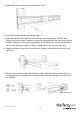
Console - Front View (open) Mounting the Console 1. Loosen the rear screws (pre-installed in side rails) and adjust the length of the rear bracket to fit the depth of your cabinet: 2.
3. Tighten the screws that were loosened in Step 1: 4. Install the remaining rail, repeating Steps 1-3. 5. Slide the Module onto the Console side rails, connecting the Module and Console using the male Centronics connector provided by the Console, and the female Centronics connector provided by the Module. Ensure the connection is secure, and that the module is firmly seated within the Console side rails. 6. Gently, but firmly insert the Console (with Module attached) into the left and right rails: 7.
1. Install three screws on each side of the console: 2.
Connecting the Console/Module To connect the KVM Console/Module to a computer, perform the following steps: 1. Remove the four screws from both sides of the KVM console. Be sure to retain these screws for the next installation step. 2. Attach the mounting brackets to both sides of the KVM console, using the screws removed in step 1.
3. From the rear of the cabinet, slide the KVM console onto the mounting rails. 4. Install one screw on each side of the console (as depicted below).
Connecting computers to the module Attach each of your managed computers to your StarView KVM console’s PC ports using ultra-thin KVM cables. The Module is capable of using either 2-in-1 USB or 3-in-1 PS/2 cables. Use the cables to connect one of the PC ports on the back of the switch to the computer’s keyboard, mouse, and video ports. Note: These instructions are for a single KVM switch only.
Turning on the console Make sure the power cord and all cables are connected properly. Grasp the handle of the drawer, pull the panel forward and up, then press the pushbutton in the top right hand corner to enable the TFT screen. The LED located to the left of the monitor panel should turn from orange to green, verifying that the unit is operational.
Testing the console 1. To test that the console is working properly, perform the following steps: 2. Power up the LCD Rack drawer, and then turn on your computer. 3. Make sure the video image is centered within the screen area. Use the OSD controls to adjust the image (see Panel controls and OSD functions) or press the Auto button on the right hand side of the monitor.
Input Source 1. Press the Menu button. 2. Use the Down and Up buttons to scroll. 3. Press the Menu button to enter, and you will see: VGA/DVI 4. Use the Down and Up buttons to select the input signal source. 5. Press the Menu button to save your selection. Brightness 1. Press the Menu button. 2. Use the Down and Up buttons to scroll to Brightness. 3. Press the Menu button to enter. 4. Use the Down and Up buttons to adjust the brightness of the display. 5. Press the Menu button to save your selection.
Color - Cont’d Icon Description 9300°K To set CIE coordinates at 9300°K color 7500°K To set CIE coordinates at 7500°K color 6500°K To set CIE coordinates at 6500°K color User To set user defined CIE Auto color To auto adjust color Return To exit and return to the previous page Position 1. Press the Menu button. 2. Use the Down and Up buttons to scroll. 3. Highlight Position and press the Menu button to enter, which will launch the following screen: 4. Use the Down and Up buttons to scroll. 5.
Recall 1. Press the Menu button. 2. Use the Down and Up buttons to scroll to Recall. Press the Menu button to enter, where you will be able to select Yes/No using the Down and Up buttons. Once you have done so, press the Menu button. Please Note: Selecting Yes will return your settings to the factory default state. Select No if you do not wish to make this change. Exit To exit the menu, scroll to Exit and press the Menu button.
A triangle mark (p) to the right of a name indicates the port is cascaded to a Slave; the number at the left of the triangle mark shows the number of ports the Slave has, i.e. 8 for an 8-port switch. The key brings you one level down and another screen pops up listing the names of the computers on that Slave. The name of the Slave will be shown at the upper right corner of the OSD menu. It is useful to group computers and still be able to see the group name.
Selecting Computers for Autoscan Function key - Use this key to switch the eye mark (N) of a computer on or off. First, use the up and down arrow keys to highlight it, then press to switch its eye mark on or off. If Scan Type reads ‘Ready PC + N’, only the power-on and eye mark selected computers will be displayed sequentially in Scan mode. Locking Devices (Slave or computer) Function key - To lock a device (a computer or a Slave) from unauthorized access, use Security.
Auto Scan In this mode, the Console automatically switches from one powered computer to the next, sequentially in a fixed interval. During Auto Scan mode, the OSD displays the name of the selected computer. When Auto Scan detects any keyboard or mouse activity, it suspends the scanning until activity stops; it then resumes with the next computer in sequence. To abort Auto Scan mode, press the left twice, or, press any front button. Scan Type and Scan Rate set the scan pattern.
Scan Type Ready PC + N: In Scan mode, scan through power-on and eye mark selected computers. Ready PC: In Scan mode, scan through power-on computers. The non-volatile memory stores the Scan Type setting. Scan Rate Sets the duration of a computer displayed in Auto Scan mode. The options are 3 seconds, 8 seconds, 15 seconds and 30 seconds. Scan Rate settings are stored in nonvolatile memory.
Hot-key commands A Hot-key command is a short keyboard sequence used to select a computer, to activate computer scan, etc. The Console constantly interprets keystrokes for hot-keys. A hot-key sequence starts with two left keystrokes followed by one or two more keystrokes. A built-in alarm generates a high-pitch beep for correct hot-key command; otherwise, one low-pitch beep for error and the bad key sequence will not be forwarded to the selected computer.
Hot-key commands - cont’d COMMAND HOTKEY SEQUENCE DESCRIPTION Selects the computer connected to console port “x”. For a computer connected directly to the console, “x” would be 1~8 or A~H. (Ex. Left Ctrl + Left Ctrl + B would select the computer connected to the “PC B” port on the console.) Select computer Left Ctrl + Left Ctrl + x For cascaded computers, you must first enter the port number of a slave KVM connected to the console, then enter the port number on the slave KVM where the PC is connected.
Manual Scan Adjust keyboard typematic rate Left Ctrl + Left Ctrl + F2 Use the up and down arrow keys to scroll to the previous or next computer in the sequence. Press any other key to abort manual scan. Left Ctrl + Left Ctrl + F4 Scrolls between the different typematic rates. This setting overrides that of the BIOS and the operating system. The console will generate one to four beeps, corresponding to 10, 15, 20, and 30 characters/sec respectively, to signify the typematic rate.
Specifications RACKCONS1708/GB/EU RACKCONS1716/GB Display Size Connectors 17” 19” 8 x DE15 female input (1708 only) 8 x DE15 female input (1908 only) 16 x DE15 female input (1716 only) 16 x DE15 female input (1916 only) 1 x VGA female output 1 x VGA female output Inactive: Inactive: 1 x PS/2 Keyboard 6-pin 1 x PS/2 Keyboard 6-pin Mini-Din (Female) Mini-Din (Female) 1 x PS/2 Mouse 6-pin 1 x PS/2 Mouse 6-pin Mini-Din (Female) Mini-Din (Female) Panel Type Active Matrix TFT LCD Resolution
RACKCONS1708/GB/EU RACKCONS1716/GB Keyboard / 106 key PS/2 keyboard Mouse Keyboard Language RACKCONS1908/GB RACKCONS1916/GB/EU with touchpad USA, UK, German, French, Spanish, Italian, Portuguese, Dutch, Swiss, Belgium, Swedish, Norwegian, Danish, Japan, Taiwan, Russian Sync 45~80KHz Power Source 100-240 VAC input Power Adapter 12VDC, 4A Power Consumption 25W, 19.
Technical Support StarTech.com’s lifetime technical support is an integral part of our commitment to provide industry-leading solutions. If you ever need help with your product, visit www.startech.com/support and access our comprehensive selection of online tools, documentation, and downloads. For the latest drivers/software, please visit www.startech.com/downloads Warranty Information This product is backed by a two year warranty. In addition, StarTech.
Hard-to-find made easy. At StarTech.com, that isn’t a slogan. It’s a promise. StarTech.com is your one-stop source for every connectivity part you need. From the latest technology to legacy products — and all the parts that bridge the old and new — we can help you find the parts that connect your solutions. We make it easy to locate the parts, and we quickly deliver them wherever they need to go. Just talk to one of our tech advisors or visit our website.