S354UFER Instruction Manual External Multi Bay Hard Drive Enclosure 3.5” 4 Drive eSATA USB FireWire External Multi Bay Hard Drive Enclosure with RAID Manual Revision:08/05/2010 For the most up-to-date information, please visit www.startech.
FCC Compliance Statement This equipment has been tested and found to comply with the limits for a Class B digital device, pursuant to part 15 of the FCC Rules. These limits are designed to provide reasonable protection against harmful interference in a residential installation. This equipment generates, uses and can radiate radio frequency energy and, if not installed and used in accordance with the instructions, may cause harmful interference to radio communications.
Table of Contents Introduction...................................................................... 1 Packaging Contents.....................................................................1 System Requirements..................................................................1 Installation........................................................................ 2 Hardware Installation....................................................................4 Driver Installation...................................
Introduction StarTech.com’s S354UFER External Multi Bay Enclosure is a highperformance 4-drive SATA enclosure that connects to host systems through eSATA or USB or FireWire.
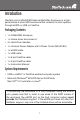
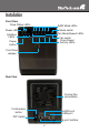
Installation Front View Drive Status LEDs RAID Mode LEDs Mode switch Fan Mode/Speed LEDs Power LED Interface LEDs Fan switch Drive Power/ Activity LEDs Power button Front Door release Rear View Cooling Fan (removable) Confirmation button eSATA port USB port DIP Switch 6-pin FireWire 2
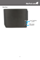
Side View 9-pin FireWire ports DIN power connector 3
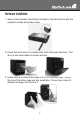
Hardware Installation 1. Secure the included Hard Drive Handles to the hard drives with the supplied screws and screw driver. 2. Press the front door in to release the latch and open the door. The door is also removable for easier access. 3. Inside will be a metal drive cage in front of the drive bays. Along the top of the drive cage are two small tabs. Press them down to release the cage and remove it.
4. Remove the cardboard inserts (if first time setup) and then insert the hard drives into the slots. If installing less than 4 drives, ensure a drive is installed in the bottom slot. This will help when reinstalling the metal cage. Hard drives can be removed from the enclosure by pressing down on the handles, then pulling them out. 5. Once all of the hard drives are installed, reinstall the metal cage and front door. Make sure the bottom of the cage stays inside of the track before closing the cover. 6.
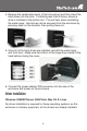
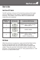
How to Use Hard Drive DIP Switch The DIP switches on the rear of the hard drive enclosure first needs to be set, depending on the number of installed hard drives in the enclosure. The number of hard drives affects the available RAID modes that can be selected.
LED Status Description ON SPAN: Spanning concatenates multiple hard drives into a single large disk. Provides no performance or redundancy benefits. OFF ON OFF ON OFF ON OFF ON OFF ON OFF RAID 0 (Stripe): Striping combines multiple disk into a single large disk array. The data is split evenly across each disk simultaneously. Read/ write performance is increased as a result, but failure of any one disk will make the entire array unusable.
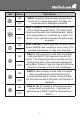
Drive Status Indicators LED Status Description ON An error has been detected on one or more hard drive. OFF ON OFF RAID array is currently rebuilding. eSATA/USB/FireWire Connectivity The LED indicators will show which host interface is currently active on the enclosure. To switch interfaces, shut the enclosure off and disconnect old cable and then connect the new cable and turn the enclosure back on.
Fan Speed Control The cooling Smart Fan is automatically controlled by an integrated thermal sensor, but can also be set manually. The fan is capable of running at 3 different speeds depending on the temperature range of the enclosure (less than 45oC, between 45-54oC, and greater than 55oC), or set manually to run constantly at a single speed.
Specifications USB 2.0, SATA 3.0 Gb/s, FireWire800 Bus Interface 1 x USB type B 1 x eSATA* External Connectors 1 x 6-pin FireWire 2 x 9-pin FireWire 1 x DIN power connector Chipset PLX OXUFS936QSE RAID Modes Span, 0, 1, 3, 5, 0+1 3 x Fan Speed 2 x Fan Mode 3 x Interface Link LEDs 6 x RAID Mode 1 x Rebuild 1 x Hard Drive Error 1 x Power USB 2.0: 480 Mbps eSATA: 3.
Specifications - Continued Power Adapter 12VDC, 5A Dimensions 215.0mm x 126.0mm x 170.0mm Weight 1.8kg Compatible Operating Systems Windows 2000/XP/Server 2003/ Vista, Mac OS 10.
Technical Support StarTech.com’s lifetime technical support is an integral part of our commitment to provide industry-leading solutions. If you ever need help with your product, visit www.startech.com/support and access our comprehensive selection of online tools, documentation, and downloads. Warranty Information This product is backed by a one year warranty. In addition, StarTech.
StarTech.com has been making “hard-to-find easy” since 1985, providing high quality solutions to a diverse IT and A/V customer base that spans many channels, including government, education and industrial facilities to name just a few. We offer an unmatched selection of computer parts, cables, A/V products, KVM and Server Management solutions, serving a worldwide market through our locations in the United States, Canada, the United Kingdom and Taiwan. Visit www.startech.