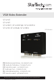
VGA Video Extender ST1214T ST1218T ST121EXT / ST121EXTGB / ST121EXTEU ST121R / ST121RGB / ST121REU *ST121R shown *actual product may vary from photos DE: Bedienungsanleitung - de.startech.com FR: Guide de l'utilisateur - fr.startech.com ES: Guía del usuario - es.startech.com IT: Guida per l'uso - it.startech.com NL: Gebruiksaanwijzing - nl.startech.com PT: Guia do usuário - pt.startech.com For the most up-to-date information, please visit: www.startech.
FCC Compliance Statement This equipment has been tested and found to comply with the limits for a Class B digital device, pursuant to part 15 of the FCC Rules. These limits are designed to provide reasonable protection against harmful interference in a residential installation. This equipment generates, uses and can radiate radio frequency energy and, if not installed and used in accordance with the instructions, may cause harmful interference to radio communications.
Table of Contents Introduction.............................................................................................................. 1 Packaging Contents.................................................................................................................................1 System Requirements.............................................................................................................................1 ST1214T...................................................................
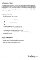
Introduction The StarTech.com Converge A/V VGA over Cat5 Video Extender system is comprised of a transmitter unit (ST1214T/ ST1218T) and a receiver unit (ST121R) and optionally a repeater unit (ST121EXT). This video extender system allows you to split and extend a single VGA source signal to up to four or eight separate remote locations. The VGA signal is extended using standard Cat5 UTP cable, with a maximum distance of up to 150m (492ft) or 250m (820ft) with a repeater.
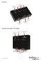
ST1214T Power connector RJ45 output VGA input (male) RJ45 output VGA output (female) ST121R / ST121RGB /ST121REU RJ45 Power input connector Signal Equalizer switch VGA output (female) Instruction Manual 2
ST121EXT / ST121EXTGB / ST121EXTEU RJ45 Signal Equalizer output switch RJ45 Power input connector VGA output (female) ST1218T RJ45 Output to Receiver Units RJ45 Output to Receiver Units VGA Output (female) Power connector Instruction Manual VGA Input (male) VGA Output (female) 3
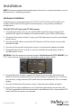
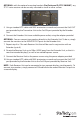
Installation NOTE: To prevent potential electrical damage to the units in some environments, ensure that the chassis is properly grounded. Hardware Installation The following instructions detail how ST1214T, ST1218T, ST121R and ST121EXT units can be used to extend a VGA signal to remote displays, using a variety of different configurations. ST1214T/ ST1218T (local) and ST121R (remote) 1.
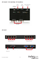
The following diagram illustrates the connection between Transmitter and receiver units. ST121R Remote Displays Cat5 cables (150m max) ST1214T VGA cables VGA cable ST1214T/ ST1218T (local), ST121EXT (extender), ST121R (Remote) Using the Transmitter Unit, you can split the VGA signal from the source into 4 separate VGA signals, for reception at remote locations.
OPTIONAL: with the optional mounting brackets (StarTech.com ID: ST121MOUNT), any ST121 series receiver can be securely mounted to a wall or other surface. 5. Using a standard UTP cable with RJ45 terminators on each end, connect the Cat5 OUT port provided by the Transmitter Unit to the Cat5 IN port provided by the Extender Unit. 6. Connect the Extender Unit to an available power outlet, using the adapter provided. OPTIONAL: You can connect two monitors directly to the Extender Unit.
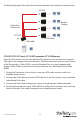
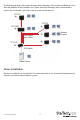
The following diagram illustrates the connection between Transmitter and Receiver units, with the addition of an Extender Unit. Please note that although only one Extender is used in this illustration, up to four can be used simultaneously. ST121R ST121R ST121EXT Remote Displays Cat5 cables (max 150m) ST1214T VGA cable Video Source Driver Installation No driver installation is required for this video extender as it is an external hardware only solution, invisible to the computer system.
Operation ST1214T/ ST1218T, ST121EXT and ST121R all provide LED indicators, allowing simple operating status monitoring. Once the power adapter has been connected, the Power LED will become illuminated; similarly, when the unit is in use (i.e. transmitting a video signal), the Active LED will become illuminated. Signal Equalizer Selector (ST121R, ST121EXT) The Signal Equalizer Selector on the Receiver and Extender Units can be adjusted to obtain the optimal video signal for various cable lengths.
Specifications Connectors ST1214T ST1218T 1 x DE-15 VGA male 1 x DE-15 VGA female 4 x RJ45 Ethernet female 1 x Power Connector 1 x DE-15 VGA male 2 x DE-15 VGA female 8 x RJ45 Ethernet female 1 x Power Connector LEDs Power, Active Maximum Distance 150m (492 ft) @ 1024x768 Power Supply 9 ~ 12V DC Dimensions 63.89mm x 103.0mm x 20.58mm 180.0mm x 85.0mm 20.
Technical Support StarTech.com’s lifetime technical support is an integral part of our commitment to provide industry-leading solutions. If you ever need help with your product, visit www.startech.com/support and access our comprehensive selection of online tools, documentation, and downloads. For the latest drivers/software, please visit www.startech.com/downloads Warranty Information This product is backed by a two year warranty. In addition, StarTech.
Hard-to-find made easy. At StarTech.com, that isn’t a slogan. It’s a promise. StarTech.com is your one-stop source for every connectivity part you need. From the latest technology to legacy products — and all the parts that bridge the old and new — we can help you find the parts that connect your solutions. We make it easy to locate the parts, and we quickly deliver them wherever they need to go. Just talk to one of our tech advisors or visit our website.