ST1214T / ST1214TGB / ST1214TEU ST1218T ST121R / ST121RGB / ST121REU ST121EXT / ST121EXTGB / ST121EXTEU Instruction Manual VGA Video Extender 4/8-Port VGA over Cat5 Transmitter VGA over Cat5 Receiver VGA over Cat5 Extender
FCC Compliance Statement This equipment has been tested and found to comply with the limits for a Class B digital device, pursuant to part 15 of the FCC Rules. These limits are designed to provide reasonable protection against harmful interference in a residential installation. This equipment generates, uses and can radiate radio frequency energy and, if not installed and used in accordance with the instructions, may cause harmful interference to radio communications.
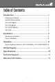
Table of Contents Introduction...................................................................... 1 Packaging Contents.....................................................................1 System Requirements..................................................................1 ST1214T/GB/EU..........................................................................2 ST121R/GB/EU............................................................................2 ST121EXT/GB/EU........................................
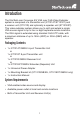
Introduction The StarTech.com Converge A/V VGA over Cat5 Video Extender system is comprised of a transmitter unit (ST1214T/ST1218T) and a receiver unit (ST121R) and optionally a repeater unit (ST121EXT). This video extender system allows you to split and extend a single VGA source signal to up to four or eight separate remote locations. The VGA signal is extended using standard Cat5 UTP cable, with a maximum distance of up to 150m (492ft) or 300m (984ft) with a repeater.
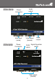
ST1214T/GB/EU VGA input (male) ST121R/GB/EU RJ45 output Power Connector Power Connector VGA output (female) RJ45 output RJ45 output Signal Equalizer switch VGA output (female) 2
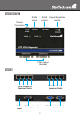
ST121EXT/GB/EU Power Connector RJ45 Signal Equalizer switch output RJ45 input VGA output (female) ST1218T RJ45 Output to Receiver Units Power Input RJ45 Output to Receiver Units VGA Input (male) VGA Output (female) 3
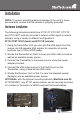
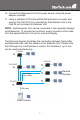
Installation NOTE: To prevent potential electrical damage to the units in some environments, ensure that the chassis is properly grounded. Hardware Installation The following instructions detail how ST1214T, ST1218T, ST121R and ST121EXT units can be used to extend a VGA signal to remote displays, using a variety of different configurations. ST1214T/ST1218T (local) and ST121R (remote) 1.
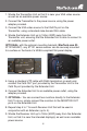
6. Connect the Receiver to the power source using the power adapter provided. 7. Using the Monitor Out ports, connect the Receiver to the display. Note that each Receiver unit can be connected to two separate displays simultaneously. To connect two monitors, simply connect a VGA cable from the second Monitor Out to a second display. 8.
1. Situate the Transmitter Unit so that it is near your VGA video source as well as an available power source. 2. Connect the Transmitter to the power source, using the power adapter provided. 3. Connect the VGA video source to the VGA IN port on the Transmitter, using a standard male-female VGA cable. 4. Situate the Extender Unit up to 150m (492ft) away from the Transmitter unit, ensuring that the Extender Unit is able to connect to an available power outlet.
. Connect the Receiver Unit to the power source using the power adapter provided. 11. Using a standard UTP cable with RJ45 terminators on each end, connect the Cat5 OUT port provided by the Extender Unit to the Cat5 IN port provided by Receiver Unit. NOTE: Each Receiver Unit can be connected to two separate displays simultaneously. To connect two monitors, simply connect a VGA cable from the second Monitor Out port to a second display.
Driver Installation No driver installation is required for this video extender as it is an external hardware only solution, invisible to the computer system. Operation ST1214T/ST1218T, ST121EXT and ST121R all provide LED indicators, allowing simple operating status monitoring. Once the power adapter has been connected, the Power LED will become illuminated; similarly, when the unit is in use (i.e. transmitting a video signal), the Active LED will become illuminated.
Wiring Diagram The Video Extenders requires an unshielded twisted pair Cat5 cable no longer than 150m (492ft). The cable must be wired according to the EIA/TIA 568B industry standard as shown below.
Specifications Connectors ST1214T ST1214TGB ST1214TEU ST1218T 1 x DE-15 VGA male 1 x DE-15 VGA female 4 x RJ45 1 x Power Connector 1 x DE-15 VGA male 1 x DE-15 VGA female 8 x RJ45 1 x Power Connector LEDs Power, Active Maximum Distance 150m (492 ft) @ 1024x768 Power Supply 12VDC, 1.5A Dimensions 63.89mm x 103.0mm x 20.58mm 180.0mm x 85.0mm 20.
Technical Support StarTech.com’s lifetime technical support is an integral part of our commitment to provide industry-leading solutions. If you ever need help with your product, visit www.startech.com/support and access our comprehensive selection of online tools, documentation, and downloads. Warranty Information These products are backed by a one year warranty. In addition, StarTech.
StarTech.com has been making “hard-to-find easy” since 1985, providing high quality solutions to a diverse IT and A/V customer base that spans many channels, including government, education and industrial facilities to name just a few. We offer an unmatched selection of computer parts, cables, A/V products, KVM and Server Management solutions, serving a worldwide market through our locations in the United States, Canada, the United Kingdom and Taiwan. Visit www.startech.