
Owners manual


3
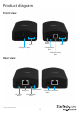
LED indicators
The USB2001EXT2P features four LEDs on both the local extender and the remote unit.
About the Mode button and
the Conguration port
Mode button - Used to enter the boot loader mode for rmware upgrades.
Conguration port - Used for rmware upgrades and data collection.
LED Status
Power The unit is powered.
Link
A link is established between the local
extender and the remote unit.
Host
The local extender is connected to a host
computer.
Activity
A USB device is connected to the remote
unit and activity is occurring.
Instruction manual
3
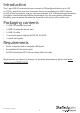
Installing the extender
The USB2001EXT2P features both a local and a remote extender unit. The local
extender connects to your host computer system, while the remote extender connects
to your remote USB device. Both devices are then connected together using standard
Cat5e cable. The provided power adapter must be connected to the local or remote
unit for the extender to properly function. Follow the below instructions to install the
extender.
Install the extender
1. Connect the USB 2.0 cable (included) to the local unit’s host port and to the host
computer’s USB-A port.
2. Connect a Cat5e Ethernet cable to the local unit’s RJ45 port and to the remote unit’s
RJ45 port.
3. Connect your USB peripheral device to the remote unit’s USB-A port.
4. Select the appropriate power cord for your region (NA/JP, UK, EU, or AU) and
connect it to the power adapter.
5. Connect the power adapter to an AC electrical outlet and then to the remote unit’s
DC (power input) port.