2x4 Port Matrix DVI Audio Video Switch VS420RDVIA *actual product may vary from photos DE: Bedienungsanleitung - de.startech.com FR: Guide de l'utilisateur - fr.startech.com ES: Guía del usuario - es.startech.com IT: Guida per l'uso - it.startech.com NL: Gebruiksaanwijzing - nl.startech.com PT: Guia do usuário - pt.startech.com For the most up-to-date information, please visit: www.startech.
FCC Compliance Statement This equipment has been tested and found to comply with the limits for a Class B digital device, pursuant to part 15 of the FCC Rules. These limits are designed to provide reasonable protection against harmful interference in a residential installation. This equipment generates, uses and can radiate radio frequency energy and, if not installed and used in accordance with the instructions, may cause harmful interference to radio communications.
Table of Contents Introduction.............................................................................................1 Packaging Contents.................................................................................................................................. 1 System Requirements............................................................................................................................... 1 Installation..........................................................................
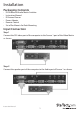
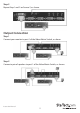
Installation Packaging Contents • • • • • • DVI Video and Audio Matrix Switcher Instruction Manual IR External Sensor Power Adapter Remote Control Set of Ear-Mounts for Rack Mounting Input Connection Step 1 Connect the DVI video port of the computer to the Source 1 port of the Video Matrix as shown. Step 2 Connect the speaker port of the computer to the Audio port of Source 1 as shown.
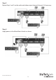
Step 3 Repeat Step 1 and 2 on Source 2, as shown. Output Connection Step 1 Connect your monitor to port 1 of the Video Matrix Switch, as shown Step 2 Connect a pair of speakers to port 1 of the Video Matrix Switch, as shown.
Step 3 Repeat Step 1 and 2 on the audio and video output channels for port 2, if necessary. Step 4 Apply power to the Video Matrix Switch as shown.
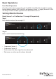
Basic Operations Front Panel Operation Once the unit has been powered on, all 4 red LEDs should be illuminated. Due to the factory default settings, if all 4 red LEDs are blinking, source 1 is empty. When all 4 LEDs are always ON then a video signal has been detected at source 1. Setting Monitor Routes Route Source 1 or 2 to Monitors 1 through 4 Respectively Step 1 Press the desired port, for example “4”. Step 2 LEDs 1 and 2 should now be blinking. • • • • 1 represents Source 1. 2 represents Source 2.
Step 3 Press 1 or 2 within 3 seconds to select Source 1 or Source 2. After selecting, LED 4 will become either red or orange. • Red means Source 1 is selected • Orange means Source 2 is selected Step 4 Repeat Step 1 through 3 to route other ports. Remote Control Operation Using the included external sensor, the user has two methods of achieving remote control of the unit within a range of 5 meters. Without the external sensor connected to the unit, the remote control communicates with the internal sensor.
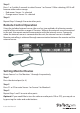
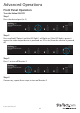
Advanced Operations Front Panel Operation Turn the Video ON/OFF Step 1 Press the desired port (ie. 2). Step 2 Press and hold “Option” and the LED light 1 will light up. If the LED light is green it means the video output device is powered on. If it is red, then the monitor is powerd off. Step 3 Press 1 to turn off Monitor 2. Step 4 If necessary, repeat these steps to turn on Monitor 2.
Turn the Audio ON/OFF Step 1 Press the desired port (ie. 1). Step 2 Press and hold “Option” and the LED light 2 will light up. If the LED light is green, it means the audio output is powered on. If it is red, then the audio output is powered off. Step 3 Press 2 to turn off the audio of Monitor 1. Step 4 If necessary repeat Step 1 through Step 3 to turn on the audio of Monitor 1.
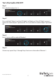
Turn ON/OFF the Auto Scan In the auto scan mode, the Video Matrix Switch automatically swithces between Source 1 and Source 2 sequentially for a particular monitor. Step 1 Press the desired port (ie. 4). Step 2 Press and hold Option. Step 3 Press 3 to turn on the auto scan mode for Monitor 4. Step 4 If necessary, repeat Step 1 through Step 3 to turn off the auto scan mode for Monitor 4.
Set the Auto Scan Time Interval Step 1 Press 3 and 4 at the same time. Step 2 All four LEDs should be blinking. Press one to set the auto scan time interval. • • • • 1 represents 8 seconds 2 represents 15 seconds 3 represents 30 seconds 4 represents 45 seconds Reset the Unit to its Default Settings 1. Power off the Video Matrix Switch. 2. Press and hold Option. 3. Power on the Video Matrix Switch. 4. Press 1 to reset everything back to the default settings.
Unit Stack This function allows the user to use one single remote control to command up to 16 Video Matrix Switch units. Setting the Remote Controlling ID on the system 1. Power off the Video Matrix Switch. 2. Press and hold 1 and 2 at the same time. 3. Power on the Video Matrix Switch. 4. Release 1 and 2. 5. Select any one of the 1 through 8 remote control buttons, 4 for example. This sets the current Video Matrix Switch remote controlling ID to 4. 6.
5. Press 1 once or twice to adjust the input video strength of the selected port. The colour of the LED will indicate the strength of the video signal. If it is green, the normal strength is in use. Red indicates the use of the enhance strength feature. OR Press 3 once or twoce to adjust the output current of the selected port. The colour of the LED will indicate the output current. If it is green, the normal current is in use, while red indicates the use of the enhanced current.
Specifications VS420RDVIA Number of Video Source Ports 2 Number of Monitor Ports 4 Video Type DVI Remote Control Yes Remote Control Extender Jack Yes Push Button Control 5 LEDs 5 Hot-Plug & Play Yes Rack-Mounted 19” industry standard Automatic Scan Interval 8, 15, 30, 45 seconds DVI Cable Length (Max) 5m Video Resolution (Max) 1600 x 1200 Monitor Connector DVI female x 4 H x W x D (mm) (Inches) 41 x 220 x 97 (1.6 x 8.66 x 3.
Technical Support StarTech.com’s lifetime technical support is an integral part of our commitment to provide industry-leading solutions. If you ever need help with your product, visit www.startech.com/support and access our comprehensive selection of online tools, documentation, and downloads. For the latest drivers/software, please visit www.startech.com/downloads Warranty Information This product is backed by a two year warranty. In addition, StarTech.
Hard-to-find made easy. At StarTech.com, that isn’t a slogan. It’s a promise. StarTech.com is your one-stop source for every connectivity part you need. From the latest technology to legacy products — and all the parts that bridge the old and new — we can help you find the parts that connect your solutions. We make it easy to locate the parts, and we quickly deliver them wherever they need to go. Just talk to one of our tech advisors or visit our website.