Single Desk-Mount Monitor Arm | Full Motion Articulating with 2x USB 3.0 Ports Actual product may vary from photos User Manual SKU#: ARMPIVOT2USB3 For the latest information and specifications visit www.startech.
Compliance Statements Use of Trademarks, Registered Trademarks, and other Protected Names and Symbols This manual may make reference to trademarks, registered trademarks, and other protected names and/or symbols of third-party companies not related in any way to StarTech.com. Where they occur these references are for illustrative purposes only and do not represent an endorsement of a product or service by StarTech.
Warning Statements • Make sure that you assemble this product according to the instructions. • Do not exceed the weight capacity of this product. Overloading this product might result in injury or property damage. This product can support the following weight: 17.6 lb. (8 kg). • This product is intended for indoor use only and should not be used outdoors. Varningsmeddelanden • Se till att du monterar produkten i enlighet med instruktionerna. • Överskrid inte produktens viktkapacitet.
• Il prodotto è destinato all’uso in ambienti interni. Se ne sconsiglia l’impiego in ambienti esterni. Mensagens de aviso • Certifique-se de que monta este produto de acordo com as instruções. • Não exceda a capacidade de peso deste produto. Sobrecarregar este produto pode resultar em ferimentos ou danos de propriedade. Este produto pode suportar o seguinte peso: 8 kg. • Este produto destina-se apenas a uma utilização no interior e não deve ser utilizado no exterior.
Safety Statements Safety Measures • Cables (including power and charging cables) should be placed and routed to avoid creating electric, tripping or safety hazards.
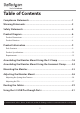
Table of Contents Compliance Statements.........................................................................1 Warning Statements...............................................................................2 Safety Statements...................................................................................4 Product Diagram.....................................................................................6 Product Dimensions.............................................................................
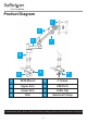
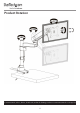
Product Diagram 1 2 3 7 4 6 5 8 1 VESA Mount 5 C-Clamp 2 Upper Arm 6 USB Ports 3 Lower Arm 7 Cable Clip 4 Pole 8 Grommet Clamp To view manuals, videos, drivers, downloads, technical drawings, and more visit www.startech.
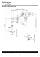
Product Dimensions To view manuals, videos, drivers, downloads, technical drawings, and more visit www.startech.
Product Rotation To view manuals, videos, drivers, downloads, technical drawings, and more visit www.startech.
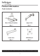
Product Information Pack Contents Base Clamp Assembly Upper Arm Qty: 1 Qty: 1 Lower Arm VESA Mount Qty: 1 Qty: 1 To view manuals, videos, drivers, downloads, technical drawings, and more visit www.startech.
Tool Clip Grommet Plate Qty: 1 Qty: 1 Grommet Screw 3 mm Hex Key Qty: 1 Qty: 1 To view manuals, videos, drivers, downloads, technical drawings, and more visit www.startech.
6 mm Hex Key M4 x 12 mm Screws Qty: 1 Qty: 4 M5 x 12 mm Screws Washers Qty: 4 Qty: 4 To view manuals, videos, drivers, downloads, technical drawings, and more visit www.startech.
Arm Shoulder Cable Clip Qty: 1 Qty: 1 Pole Qty: 1 To view manuals, videos, drivers, downloads, technical drawings, and more visit www.startech.
Product Specifications 75 x 75 100 x 100 VESA - 900 to + 900 Rotation - 900 to + 900 Tilt LB kg 17.6 lb. (8 kg) Weight To view manuals, videos, drivers, downloads, technical drawings, and more visit www.startech.
” to 34” Screen Size -900 to +900 Swivel To view manuals, videos, drivers, downloads, technical drawings, and more visit www.startech.
Requirements Tools • Phillips Head Screwdriver x 1 Displays • 15” to 34” Display x 1 Optional • USB Cables x 2 • USB Compatible Devices x 2 To view manuals, videos, drivers, downloads, technical drawings, and more visit www.startech.
Assembling the Monitor Mount Using the C-Clamp 1. Using the 6 mm Hex Key loosen the C-Clamp Screw, opening the C-Clamp to the thickness of the Mounting Surface you wish to mount the Monitor Mount to. The C-Clamp Screw is located in the center of the Mounting Peg on the Base Clamp Assembly. Loosening the C-Clamp Screw 2. Align the C-Clamp with the edge of the Mounting Surface. To view manuals, videos, drivers, downloads, technical drawings, and more visit www.startech.
3. Gently push the USB Cables coming out of the back of the Base Clamp Assembly into the two Cable Grooves on the back of the Base Clamp Assembly. Routing the USB Cables Through the Cable Grooves 4. Slide the C-Clamp over the edge of the Mounting Surface. The C-Clamp accommodates ranges from 10 mm (.3”) to 50 mm (1.9”). 5.
Tightening the C-Clamp Screw 6. Align the Pole with the Mounting Hole on the Base Clamp Assembly. 7. Using your hand, screw the Pole into the Base Clamp Assembly. 8. Using the 3 mm Hex Key, tighten the small screw located on the Neck of the Mounting Hole on the Base Clamp Assembly to secure the Pole. To view manuals, videos, drivers, downloads, technical drawings, and more visit www.startech.
Mounting the Pole to the Base Clamp Assembly 9. Slide the Cable Clip over-top of the Pole, sliding it down into position. To view manuals, videos, drivers, downloads, technical drawings, and more visit www.startech.
Sliding the Cable Clip over-top of the Pole 10. Slide the Arm Shoulder over-top of the Pole, sliding it down into position. 11. Turn the Locking Lever on the Arm Shoulder clock-wise, securing the Arm Shoulder into place. Note: The Locking Lever may require multiple turns in order to properly secure the Arm Shoulder in place. To view manuals, videos, drivers, downloads, technical drawings, and more visit www.startech.
Installing the Arm Shoulder 12. Align the Mounting Peg on the bottom of the Lower Arm with the Mounting Hole on the Arm Shoulder. 13. Slide the Mounting Peg on the Lower Arm into the Mounting Hole on the Arm Shoulder. 14. Using the 3 mm Hex Key, tighten the small screw located on the Arm Shoulder to secure the Lower Arm. To view manuals, videos, drivers, downloads, technical drawings, and more visit www.startech.
Installing the Lower Arm 15. Align the Mounting Peg on the bottom of the Upper Arm with the Mounting Hole on the top of the Lower Arm. 16. Slide the Mounting Peg on the Upper Arm into the Mounting Hole on the Lower Arm. To view manuals, videos, drivers, downloads, technical drawings, and more visit www.startech.
Mounting the Upper Arm to the Lower Arm 17. Using the 3 mm Hex Key to tighten the Screw on the Lower Arm securing it to the Upper Arm. To view manuals, videos, drivers, downloads, technical drawings, and more visit www.startech.
Tightening the Screw on the Lower Arm Assembling the Monitor Mount Using the Grommet Clamp 1. While holding the C-Clamp, use the 6 mm Hex Key to loosen the C-Clamp Screw and remove it from the Base Clamp Assembly. The C-Clamp Screw is located in the center of the Mounting Peg on the Base Clamp Assembly. 2. Once the C-Clamp Screw is removed the C-Clamp will also detach from the Base Clamp Assembly. To view manuals, videos, drivers, downloads, technical drawings, and more visit www.startech.
Removing C-Clamp Screw and C-Clamp 3. Align the Grommet Hole on the Base Clamp Assembly with the Grommet Hole on the Mounting Surface. 4. Insert the Grommet Screw through the center of the Mounting Peg on the Base Clamp Assembly and out the Grommet Hole on the Mounting Surface. To view manuals, videos, drivers, downloads, technical drawings, and more visit www.startech.
Inserting the Grommet Screw 5. Underneath the Mounting Surface, thread the Grommet Hole on the Grommet Plate onto the Grommet Screw. Aligning the Grommet Plate To view manuals, videos, drivers, downloads, technical drawings, and more visit www.startech.
6. While holding the Grommet Plate, use the 6 mm Hex Key, tighten the Grommet Screw, securing the Base Clamp Assembly to the Mounting Surface. Tightening the Grommet Screw 7. Align the Pole with the Mounting Hole on the Base Clamp Assembly. 8. Using your hand screw the Pole into the Base Clamp Assembly. 9. Using the 3 mm Hex Key, tighten the small screw located on the Neck of the Mounting Hole on the Base Clamp Assembly to secure the Pole.
Mounting the Pole to the Base Clamp Assembly 10. Slide the Cable Clip over-top of the Pole, sliding it down into position. To view manuals, videos, drivers, downloads, technical drawings, and more visit www.startech.
Sliding the Cable Clip over-top of the Pole 11. Slide the Arm Shoulder over-top of the Pole, sliding it down into position. 12. Turn the Locking Lever on the Arm Shoulder clock-wise, securing the Arm Shoulder into place. Note: The Locking Lever may require multiple turns in order to properly secure the Arm Shoulder in place. To view manuals, videos, drivers, downloads, technical drawings, and more visit www.startech.
Installing the Arm Shoulder 13. Align the Mounting Peg on the bottom of the Lower Arm with the Mounting Hole on the Arm Shoulder. 14. Slide the Mounting Peg on the Lower Arm into the Mounting Hole on the Arm Shoulder. 15. Using the 3 mm Hex Key, tighten the small screw located on the Arm Shoulder to secure the Lower Arm. To view manuals, videos, drivers, downloads, technical drawings, and more visit www.startech.
Installing the Lower Arm 16. Align the Mounting Peg on the bottom of the Upper Arm with the Mounting Hole on the top of the Lower Arm. 17. Slide the Mounting Peg on the Upper Arm into the Mounting Hole on the Lower Arm. To view manuals, videos, drivers, downloads, technical drawings, and more visit www.startech.
Mounting the Upper Arm to the Lower Arm 18. Using the 3 mm Hex Key, tighten the Screw on the Lower Arm securing it to the Upper Arm. To view manuals, videos, drivers, downloads, technical drawings, and more visit www.startech.
Tightening the Screw on the Lower Arm Mounting the Monitor 1. Place the Monitor screen side down on a flat, clean surface. 2. (Optional) Remove any Screws or Place Holders from the VESA Mounting Holes on the back of the Monitor. Note: Be careful not to remove any of the Screws holding the Monitor’s Casing together. 3. Align the Washers (included) with the VESA Mounting Holes on the back of the Monitor. To view manuals, videos, drivers, downloads, technical drawings, and more visit www.startech.
4. Align the Screw Holes on the VESA Mount with the VESA Mounting Holes on the back of the Monitor. The VESA Mount can support a 75 x 75 or 100 x 100 mounting pattern. Note When attached, the Arrow on the VESA Mount should be pointing toward the top of the Monitor. Aligning the VESA Mount with Monitor 5. Select the appropriate hardware for mounting the VESA Mount to the back of the Monitor either M4 x 12 mm, M5 x 12 mm, or customer sourced screws. 6.
Note: It is recommended that two people mount the Monitors. 8. Pull the VESA Clip on the VESA Holder back towards the Spring Arm. Pulling back the VESA Clip Note: The VESA Clip on the VESA Holder should be at the top of the VESA Holder before mounting the Monitor. 9. While holding the VESA Clip and supporting the weight of the Monitor, align the Mounting Plate of the VESA Mount with the VESA Holder on the Spring Arm. 10.
11. While holding the Monitor in place, release the VESA Clip, securing the Monitor in place. Adjusting the Monitor Mount Adjusting the Spring Arm Tension 1. Using your hand push downward on the Spring Arm and hold it in place. 2. The Spring Arm should only be placed in a horizontal position or tilted downwards. Correct Spring Arm Position 3. Use the 6 mm Hex Key to rotate the Adjustment Screw located at the back of the Spring Arm, just above the joint.
Adjusting the Spring Arm Tension Note: Be careful not to pinch your hand when making adjustments to the Monitor. Adjusting the Tilt 1. Use the 6 mm Hex Key to loosen the Tilt Adjustment Screw located at the side of the VESA Holder. To view manuals, videos, drivers, downloads, technical drawings, and more visit www.startech.
Loosening the Tilt Adjustment Screw 2. Use your hand to adjust the tilt of the Monitor. Note: Be careful not to pinch your hand when making adjustments to the Monitor. 3. When you have achieved the desired tilt, hold the Monitor in that position and tighten the Tilt Adjustment Screw. To view manuals, videos, drivers, downloads, technical drawings, and more visit www.startech.
Routing the Cables 1. Slide the Cable Cover on the Lower Arm upward to remove the Cable Cover. The Cable Cover is located along the bottom of the Lower Arm. Removing the Cable Cover 2. Run the Monitor Cables along the inside of the Upper Arm. 3. Gently push the Monitor Cables into the Cable Clip located on the inside of the Upper Arm. To view manuals, videos, drivers, downloads, technical drawings, and more visit www.startech.
Routing the Monitor Cables Along the Upper Arm 4. Route the Monitor Cables down the Lower Arm and through the Tool Clip on the back of the Base Clamp Assembly. Make sure that you leave enough slack in the Monitor Cable to compensate for arm movement and adjustments. 5. Replace the Cable Cover removed in step 1 by sliding it down the Lower Arm, securing the Cable Cover to the Lower Arm. Be careful not to pinch the Monitor Cable between the Cable Cover and Lower Arm. 6.
Routing the Monitor Cables Using the 3.0 USB Passthough Ports 1. Plug the two USB Cables on the back of the Base into USB Ports on the Host Computer. 2. Connect a USB Cable to the USB Ports on the front of the Base and the other end to a compatible USB Device. To view manuals, videos, drivers, downloads, technical drawings, and more visit www.startech.
Warranty Information This product is backed by a two-year warranty. For further information on product warranty terms and conditions, please refer to www.startech.com/warranty. Limitation of Liability In no event shall the liability of StarTech.com Ltd. and StarTech.
Hard-to-find made easy. At StarTech.com, that isn’t a slogan. It’s a promise. StarTech.com is your one-stop source for every connectivity part you need. From the latest technology to legacy products — and all the parts that bridge the old and new — we can help you find the parts that connect your solutions. We make it easy to locate the parts, and we quickly deliver them wherever they need to go. Just talk to one of our tech advisors or visit our website.