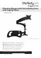
Monitor Mount with Articulating Arm and Laptop Riser ARMUNONB *actual product may vary from photos FR: Guide de l’utilisateur - fr.startech.com DE: Bedienungsanleitung - de.startech.com ES: Guía del usuario - es.startech.com NL: Gebruiksaanwijzing - nl.startech.com PT: Guia do usuário - pt.startech.com IT: Guida per l’uso - it.startech.com For the latest information, technical specifications, and support for this product, please visit www.StarTech.com/ARMUNONB.
Use of Trademarks, Registered Trademarks, and other Protected Names and Symbols This manual may make reference to trademarks, registered trademarks, and other protected names and/or symbols of third-party companies not related in any way to StarTech.com. Where they occur these references are for illustrative purposes only and do not represent an endorsement of a product or service by StarTech.com, or an endorsement of the product(s) to which this manual applies by the third-party company in question.
Table of Contents Introduction.............................................................................................1 Product diagram......................................................................................................................................... 1 Technical specifications........................................................................................................................... 3 Package contents..................................................................
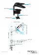
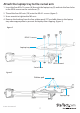
Introduction The ARMUNONB offers a convenient and easy way to raise your laptop and monitor off of your desk. The ARMUNONB is straightforward to put together and the sturdy design provides a safe way to mount your monitor and laptop.
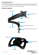
Base Desk clamp Clamp screw Clamping knob Instruction manual 2
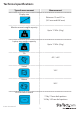
Technical specifications Type of measurement Measurement Display size Between 15 and 27 in. (381 mm and 686 mm) Monitor mount weight capacity Up to 17.6 lb. (8 kg) Laptop tray weight capacity Up to 17.6 lb.
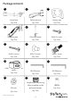
Package contents 1 3 2 Swivel arm Extension arm Laptop tray Qty: One Qty: One Qty: One 4 6 5 Spring arm Pole and clamp M4x12 screws Qty: One Qty: One Qty: Four 7 8 9 M4x30 screws M5x12 screws M6x25 screw Qty: Four Qty: Four Qty: One 10 12 11 Cable-management clip (pole) M3 Allen key Qty: One 13 M5 Allen key Qty: One 14 Qty: One 15 Height-adjustment ring M5 nuts Qty: Four Instruction manual (ships installed on the pole and clamp) Qty: One 4 Spacers Qty: Four
16 17 Cable-management clip (laptop arm) Qty: Two 18 Rubber pads Plastic cap Qty: Four Qty: One 19 Instruction manual Qty: One Installation requirements • Phillips screwdriver • Adjustable wrench Installation requirements are subject to change. For the latest requirements, please visit www.StarTech.com/ARMUNONB.
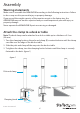
Assembly Warning statements Make sure to assemble the ARMUNONB according to the following instructions. Failure to do so may result in personal injury or property damage. If you exceed the weight capacity of the monitor mount or the laptop tray, the ARMUNONB may not work as expected and you could experience personal injury or property damage. Never operate the ARMUNONB if parts are missing or damaged.
Attach the laptop tray to the swivel arm 1. Insert the four M5x12 screws (8) through the laptop tray (3) and into the four holes in the VESA mount on the swivel arm (1). 2. Thread the four M5 nuts (13) onto the M5x12 screws. (figure 2) 3. Use a wrench to tighten the M5 nuts. 4. Remove the backing from the four rubber pads (17) and affix them to the laptop tray where appropriate to prevent the laptop from slipping.
Attach the swivel arm to the pole and clamp 1. Turn the adjustable collar on the height-adjustment ring (14) counterclockwise and pull the height-adjustment ring off of the pole and clamp (5). (figure 4) 2. Slide the swivel arm (1) down the pole and clamp. (figure 5) 3. When the swivel arm is at the desired height, use the M5 Allen key (11) to turn the screw in the swivel arm clockwise to tighten it in place.
figure 6 M5 Allen key Instruction manual Swivel arm 9
Attach the extension arm 1. Slide the height-adjustment ring (14) down the pole and clamp (5) until it’s at the height that you want the extension arm to sit at. 2. Turn the adjustable collar on the height-adjustment ring clockwise to tighten it in place. 3. Slide the extension arm (2) down the pole until it’s sitting on the height-adjustment ring. (figure 7) 4. To change the swivel tension of the extension arm, use the M3 Allen key (11) to turn the screws in the extension arm clockwise or counterclockwise.
Attach a display to the spring arm Caution! To prevent scratching, you should handle the surface of the display with care when you attach it to the spring arm. If you exceed the weight capacity of the mount, the ARMUNONB may not work as expected and you could experience personal injury or property damage. 1.
Attach the spring arm to the extension arm 1. Carefully lift the spring arm (4) with the display attached and place it onto the extension arm (2). (figure 11) 2. Insert the M6x25 screw (9) through the extension arm, the spring arm, and into the plastic cap (18). (figure 12) 3. Use a screwdriver to tighten the M6x25 screw.
Adjust the height tension of the spring arm You can adjust the height tension of the spring arm to make sure that the display stays in place, regardless of the weight of the display. 1. If the display doesn’t stay in place or the movement is stiff, do one of the following: • To increase the tension, use the M5 Allen key (12) to turn the screw in the spring arm (4) clockwise. (figure 13) • To decrease the tension, use the M5 Allen key (12) to turn the screw in the spring arm (4) counterclockwise.
Adjust the swivel tension of the display mount • To change the swivel tension of the display mount, use the M5 Allen key (12) to turn the screw on the top of the VESA mount clockwise or counterclockwise.
Route the cables Warning! Make sure that you leave enough slack at the arm joints so that the arms can be fully extended. Make sure that the cables that you’re routing are unplugged before you complete the following steps. 1. Pull out the cable rungs on the spring arm (4) and thread the display cable through the rungs. 2. Thread the display cable through the cavity in the underside of the extension arm (2). 3.
Technical support StarTech.com’s lifetime technical support is an integral part of our commitment to provide industry-leading solutions. If you ever need help with your product, visit www.startech.com/support and access our comprehensive selection of online tools, documentation, and downloads. For the latest drivers/software, please visit www.startech.com/downloads Warranty information This product is backed by a two-year warranty. StarTech.
Hard-to-find made easy. At StarTech.com, that isn’t a slogan. It’s a promise. StarTech.com is your one-stop source for every connectivity part you need. From the latest technology to legacy products — and all the parts that bridge the old and new — we can help you find the parts that connect your solutions. We make it easy to locate the parts, and we quickly deliver them wherever they need to go. Just talk to one of our tech advisors or visit our website.