Rack Console with KVM Switch 17” LCD Rackmount Console with 8 Port KVM 19” LCD Rackmount Console with 16 Port KVM RACKCONS1708 RACKCONS1916 Instruction Manual Actual product may vary from photo
FCC Compliance Statement This equipment has been tested and found to comply with the limits for a Class B digital device, pursuant to part 15 of the FCC Rules. These limits are designed to provide reasonable protection against harmful interference in a residential installation. This equipment generates, uses and can radiate radio frequency energy and, if not installed and used in accordance with the instructions, may cause harmful interference to radio communications.
Instruction Manual Table of Contents Introduction . . . . . . . . . . . . . . . . . . . . . . . . . . . . . . . . . . . . . . . . . . . . . . . . . . . . .1 Features . . . . . . . . . . . . . . . . . . . . . . . . . . . . . . . . . . . . . . . . . . . . . . . .1 Before You Begin . . . . . . . . . . . . . . . . . . . . . . . . . . . . . . . . . . . . . . . . . . . . . . . . .1 Package Contents . . . . . . . . . . . . . . . . . . . . . . . . . . . . . . . . . . . . . . . .1 Accessory Products from StarTech.
Instruction Manual Introduction Thank you for purchasing a StarTech.com LCD Rack Console with KVM. This product allows you to manage multiple computers using an integrated keyboard, mouse, and TFT screen that slides into a compact 1U of rack space when not in use.
Instruction Manual SV125 Sun to PS/2 Keyboard/Mouse Converter SVECONUS10 10 ft Ultra-Thin USB 2-in-1 KVM Cable SVECONUS15 15 ft Ultra-Thin USB 2-in-1 KVM Cable SVECONUS6 6 ft Ultra-Thin USB 2-in-1 KVM Cable SVECON10 6 ft.
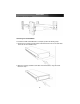
Instruction Manual Installation and usage Hardware kit contents Screw kit Side Rails with front and rear brackets (2) Keys (2) Mounting Brackets Please note: RACKCONS1708/RACKCONS1916 is comprised of two distinct components - a Rackmountable Console and a Rackmountable KVM Module, as illustrated below. The two devices are attached via a Centronics connector on the Rear panel of the Console and similarly the front panel of the Module.
Instruction Manual Mounting the Console 1. Loosen the rear screws (pre-installed in side rails) and adjust the length of the rear bracket to fit the depth of your cabinet: 2. Install the rail into the cabinet: 3. Tighten the screws that were loosened in Step 1: 4. Install the remaining rail, repeating Steps 1-3.
Instruction Manual 5. Slide the Module onto the Console side rails, connecting the Module and Console using the male Centronics connector provided by the Console, and the female Centronics connector provided by the Module. Ensure the connection is secure, and that the module is firmly seated within the Console side rails. 6. Gently, but firmly insert the Console (with Module attached) into the left and right rails: 6.
Instruction Manual 8. Installation is now complete: Connecting the Console/Module To connect the KVM Console/Module to a computer, perform the following steps: 1. Remove the four screws from both sides of the KVM console. Be sure to retain these screws for the next installation step. 2. Attach the mounting brackets to both sides of the KVM console, using the screws removed in step 1.
Instruction Manual 3. From the rear of the cabinet, slide the KVM console onto the mounting rails. 4. Install one screw on each side of the console (as depicted below). Connecting computers to the module Attach each of your managed computers to your StarView KVM console’s PC ports using ultra-thin KVM cables. The Module is capable of using either 2-in-1 USB or 3-in-1 PS/2 cables. Use the cables to connect one of the PC ports on the back of the switch to the computer's keyboard, mouse, and video ports.
Instruction Manual Cascade Configuration You can connect a second level of KVMs to one or more of your Master KVM console’s PC ports. The KVM switches connected to the Master console are known as Slaves. Once connected, the KVM switches will automatically configure themselves as either Masters or Slaves. You can only connect an equal or “smaller” KVM to the Master KVM. For example, a 16-port Master KVM switch can have both 16-port and 8-port slaves.
Instruction Manual example, the control panel may include an Advanced Properties button, an Adjustment tab, or a Refresh tab for changing other settings. Other video cards have a separate utility for setting display properties. Whenever you change the resolution, color, or refresh rate, the image size, position, or shape may change. This behavior is normal. You can readjust the image using the monitor on-screen controls.
Instruction Manual Auto tune Press the Auto tune button. The panel will adjust the display size automatically and also tune the panel to its optimized state. Input Source 1. Press the Menu button. 2. Use the Down and Up buttons to scroll. 3. Press the Menu button to enter, and you will see: VGA/DVI 4. Use the Down and Up buttons to select the input signal source. 5. Press the Menu button to save your selection. Brightness 1. Press the Menu button. 2. Use the Down and Up buttons to scroll to Brightness. 3.
Instruction Manual Color 1. Press the Menu button. 2. Use the Down and Up button to scroll. 3.
Instruction Manual Language 1. Press the Menu button. 2. Use the Down and Up buttons to scroll. 3. Highlight Language, and press the Menu button to select, which will launch the following screen: English German French Italian Spanish 4. Use the Down and Up buttons to scroll, and highlight the preferred language. 5. Press the Menu button to save your selection. Recall 1. Press the Menu button. 2. Use the Down and Up buttons to scroll to Recall.
Instruction Manual Module operation Push Button Selection A computer may be selected by pressing the push buttons above the keyboard on the Console, by issuing hot-key commands or by activating the OSD window. The indicator LEDs change to reflect the computer port selected (red). The indicator flashes red when it is in either Auto Scan or Manual Scan mode. The K/M Reset function (on the module) reconfigures your system without powering down your computers or your KVM switch.
Instruction Manual select it. Or, you may press to exit the OSD and remove the OSD menu from the display; the status window returns to the display and indicates the currently selected computer or operating status. A triangle mark to the right of a name indicates the port is cascaded to a Slave; the number at the left of the triangle mark shows the number of ports the Slave has, i.e. 8 for an 8-port switch.
Instruction Manual Function key - More functions are available by hitting . A new screen pops up displaying more functions as described below. Most of them are marked with a ) indicating there are options to choose from. Using the < > and < > arrow triangle ( keys, select the functions and press . Available options will be shown in the middle of the screen. Again, using the < > and < > arrow keys to view options, then press to select it. You can press to exit at any time.
Instruction Manual the Keyboard Speed setting. Hotkey Menu When you hit the left key twice within two seconds, the Hotkey Menu appears displaying a list of hot-key commands if the option is On. The Hotkey Menu can be turned Off if you prefer not to see it when the left key is hit twice. The non-volatile memory stores the Hotkey Menu setting.
Instruction Manual Left Ctrl + left Ctrl + 7 Selects a computer connected to port 7 of the Master. Left Ctrl + left Ctrl + 6 + C Selects a computer connected to port C of a Slave connected to port 6 of the Master. • To start Auto Scan, automatically scan power-on computers one by one at a fixed interval: Left Ctrl + left Ctrl + F 1 When Auto Scan detects any keyboard or mouse activity, it suspends the scanning till activity stops; it then resumes with the next computer in sequence.
Instruction Manual Change Configuration while Running A device (a computer or a KVM switch) at any 'PC x' port can be changed at any time after initial power-up. If you change any one of the PC 1 to PC 8 ports connection from a computer to a Slave or vice versa, or replace the devices of a port, the OSD will update this change the next time it is activated. Note: Any new device must be turned off before it is connected to the Master.
Instruction Manual Specifications RACKCONS1708 Certifications RACKCONS1916 CSA, FCC, UL, CUL, CE, RoHS Connectors 8 x VGA female input 1 x VGA female output 16 x VGA female input 1 x VGA female output Inactive: 1 x PS/2 Keyboard 6-pin Mini-Din (Female) 1 x PS/2 Mouse 6-pin Mini-Din (Female) Inactive: 1 x PS/2 Keyboard 6-pin Mini-Din (Female) 1 x PS/2 Mouse 6-pin Mini-Din (Female) Power Adapter Max Resolutions Number of ports Display Size Panel Type 12V, 4A Pixel Pitch 1280 X 1024 (XGA) 8 17” Acti
Instruction Manual Technical Support StarTech.com’s lifetime technical support is an integral part of our commitment to provide industry-leading solutions. If you ever need help with your product, visit www.startech.com/support and access our comprehensive selection of online tools, documentation, and downloads. Warranty Information This product is backed by a one-year warranty. In addition, StarTech.
About StarTech.com StarTech.com is “The Professionals’ Source for Hard-to-Find Computer Parts”. Since 1985, we have been providing IT professionals with the quality products they need to complete their solutions. We offer an unmatched selection of computer parts, cables, server management solutions and A/V products and serve a worldwide market through our locations in the United States, Canada, the United Kingdom and Taiwan. Visit www.startech.