60W Ultra PoE Injector (Midspan) and Splitter Bundle Actual product may vary from photos User Manual SKU#: UPOESPLT1G For the latest information and specifications visit www.startech.
Compliance Statements FCC Compliance Statement This equipment has been tested and found to comply with the limits for a Class A digital device, pursuant to Part 15 of the FCC rules. These limits are designed to provide reasonable protection against harmful interference when the equipment is operated in a commercial environment.
Use of Trademarks, Registered Trademarks, and other Protected Names and Symbols This manual may make reference to trademarks, registered trademarks, and other protected names and/or symbols of third-party companies not related in any way to StarTech.com. Where they occur these references are for illustrative purposes only and do not represent an endorsement of a product or service by StarTech.com, or an endorsement of the product(s) to which this manual applies by the third-party company in question.
Safety Statements Safety Measures • Wiring terminations should not be made with the product and/or electric lines under power. • Product installation and/or mounting should be completed by a certified professional as per the local safety and building code guidelines. • Cables (including power and charging cables) should be placed and routed to avoid creating electric, tripping or safety hazards.
Table of Contents Compliance Statements.........................................................................i Warning Statements...............................................................................ii Safety Statements...................................................................................iii Product Diagram.....................................................................................1 Splitter ...................................................................................
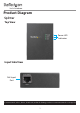
Product Diagram Splitter Top View Power LED Indicators Input Side View PoE Input Port To view manuals, videos, drivers, downloads, technical drawings, and more visit www.startech.
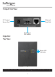
Output Side View DC Output Power Port Injector Ethernet Data Port DC Output DIP Switch Top View Power LED Indicators To view manuals, videos, drivers, downloads, technical drawings, and more visit www.startech.
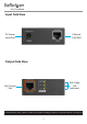
Input Side View DC Power Input Port Ethernet Data Port Output Side View PoE Usage LED Indicators PoE Output Port To view manuals, videos, drivers, downloads, technical drawings, and more visit www.startech.
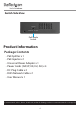
Switch Side View PoE Mode Switch Product Information Package Contents • • • • • • • PoE Splitter x 1 PoE Injector x 1 Universal Power Adapter x 1 Power Cords (NA/JP, UK, EU, AU) x 4 DC Plug Cable x 2 RJ45 Network Cable x 1 User Manual x 1 To view manuals, videos, drivers, downloads, technical drawings, and more visit www.startech.
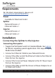
Requirements For the latest requirements, please visit www.startech.com/UPOESPLT1G. Power: • Available AC Electrical Outlet Splitter • Network Device x 1 • Ethernet Cable x 1 Injector • Network Device x 1 • Ethernet Cable x 2 Installation Connecting the Splitter to the Injector Connecting the Injector 1. Toggle the PoE Mode Switch to Standard Mode. See Legacy for details regarding special applications that require Legacy Mode to be enabled. 2. Connect an Ethernet Cable to your Network Device. 3.
Connect an Ethernet Cable to the PoE Output Port on the Injector. Connecting the Splitter 7. Toggle the DC Output Switch to the desired voltage for your application. Consult the manufacturer’s documentation to determine the proper input voltage setting for your Network Device. Note: Before changing the output voltage, disconnect the Ethernet Cable from the PoE Input Port on the Splitter. 6. 8. Connect the other end of the Ethernet Cable to the PoE Input Port on the Splitter. 9.
Note: Always disconnect the Ethernet Cable from the PoE Input Port on the Splitter before changing the output voltage. 3. Connect the other end of the Ethernet Cable to the PoE Input Port on the Splitter. 4. Connect an Ethernet Cable to the Ethernet Data Port on the Splitter. 5. Connect the other end of the Ethernet Cable to your nonPoE Network Device. 6. Connect the appropriate DC Plug Cable for your application (barrel type M-M or M-N) to the DC Output Power Port on the Splitter. 7.
7. Connect the other end of the Ethernet Cable to your PoE Power Delivery Network Device.
*Legacy Mode The legacy detection feature identifies connected devices that do not comply with the IEEE 802.3af/at/bt standard. See Injector - PoE Mode Switch for details.
Note: Always disconnect the PoE Input Cable before changing the output voltage. Injector - PoE Mode Switch The PoE Mode Switch allows you to switch between Standard and Legacy PoE modes. Standard: For all applications that use devices that conform to the IEEE 802.3af/at/bt standards. Normal use of the Injector will require this switch setting to be enabled. Note: Check the manufacturer’s technical documentation for details regarding the standards followed by the equipment in your application.
Warranty Information This product is backed by a two-year warranty. StarTech.com warrants its products against defects in materials and workmanship for the periods noted, following the initial date of purchase. During this period, the products may be returned for repair, or replacement with equivalent products at our discretion. The warranty covers parts and labor costs only. StarTech.com does not warrant its products from defects or damages arising from misuse, abuse, alteration, or normal wear and tear.
Hard-to-find made easy. At StarTech.com, that isn’t a slogan. It’s a promise. StarTech.com is your one-stop source for every connectivity part you need. From the latest technology to legacy products — and all the parts that bridge the old and new — we can help you find the parts that connect your solutions. We make it easy to locate the parts, and we quickly deliver them wherever they need to go. Just talk to one of our tech advisors or visit our website.